Aewin Technologies SGA-2210 User manual

AEWIN Technologies Co., Ltd. All rights reserved. Ver1.0 Dec. 2013
1
SGA-2210
AMD eOntario Processor based Gaming System, DirectX 11, OpenGL 4, 1 x CFast,
1 x CF, 10 x COM, 2nd RTC and NVRAM/MRAM
User’s Manual

AEWIN Technologies Co., Ltd. All rights reserved. Ver1.0 Dec. 2013
2
Table of Contents
Chapter 1. General Information.............................................................................3
1.1 Introduction .........................................................................................................3
1.2 Specification........................................................................................................4
1.3 Precautions........................................................................................................10
1.4 Layout……………… ...........................................................................................11
1.5 Dimension..........................................................................................................13
Chapter 2. Connector and Jumper Settings.......................................................15
Chapter 3. BIOS Setup............................................................................................31
3.1 Quick Setup .......................................................................................................31
3.2 Entering the CMOS Setup Program.................................................................32
3.3 Main....................................................................................................................34
3.4 Advanced ...........................................................................................................35
3.5 Chipset ...............................................................................................................36
3.6 Boot....................................................................................................................37
3.7 Security..............................................................................................................38
3.9 Save and Exit Setup..........................................................................................39

AEWIN Technologies Co., Ltd. All rights reserved. Ver1.0 Dec. 2013
3
Chapter 1. General Information
1.1 Introduction
SGA-2210 is a graphic-enhanced mainstream gaming system. “Built with AMD
eOntario chipsets, SGA-2210 can support fantastic integrated graphic performance
and reach 2,500 score while running 3DMark 2006 under 1024 x 768 x 32bits.With
UVD 3.0, SGA-2210 can offload video decode dramatically reducing CPU loading
during video play. It supports full bit-stream decoding of H.264/MPEG-4 AVC, VC-1,
DivX, Xvid, MPEG2, as well as Blu-ray.
Key features:
GLI compliant
Onboard graphic 3DMark 06 up to 2,500 score
Support Directx 11 and OpenGL 4
Support full bitstream decoding of H.264/MPEG-4 AVC, VC-1, DivX, Xvid,
MPEG2, as well as Blu-ray 3D
AC Power Fail Detection w/ interrupt
Instant ON/OFF in 500ms
Battery Low Detection
10 x COM, 2 x LAN, NVRAM, TPM, 2nd RTC
SGA-2210 provides various security mechanisms, including physical security, data
security and software security. “AC Power Fail Detection” is one of the important
features of data security. With this function, SGA-2210 can write data into NVRAM
while unpredictableAC Power Fail, and make sure the data to be secured under any
circumstance.

AEWIN Technologies Co., Ltd. All rights reserved. Ver1.0 Dec. 2013
4
1.2 Specification
GA-2210
■
■
System
CPU
AMD® T56N Dual Core 1.65GHz
BIOS
AMI® BIOS
Chipset
AMD® A55E chipset
System Memory
2 x DDR3 SODIMM socket support up to 8GB
Watchdog Timer
255 levels timer interval, (1sec. to 255min.), setup by software.
■
■
Display
Video Chipset
AMD® T56N w/ ATI® Radeon™ HD6320
- Microsoft® DirectX® 11
- OpenGL 4.0
- OpenCL 1.0
- UVD (Universal Video Decoder) 3.0; Full bitstream decoding of
H.264/MPEG-4 AVC, VC-1, DivX, Xvid, MPEG2, as well as Blu-ray
3D
Video Interface
1st display Single-link DVI 1920 ×1200 at 60 Hz
2nd display Single-link DVI 1920 ×1200 at 60 Hz(or 2nd display VGA
2048 ×1536 at 60 Hz)
■
■
Audio
Audio Chipset
HDA 5.1 Channel
Power amp.
N/A
Audio Interface
Front, Surround, CEN/SUB
■
■
Ethernet
Ethernet Interface
2 x PCIe x1 Gigabit Ethernet
■
■
Storage
SSD
1 x CF
1 x CFast
2GB NANDrive (Optional 8GB)
HDD
Two SATA connectors
■
■
Security
Physical Security
Intrusion Detection
Onboard Storage
Software Security
Boot ROM
TPM 1.2
FPGA
AEWIN Locking

AEWIN Technologies Co., Ltd. All rights reserved. Ver1.0 Dec. 2013
5
Data Security
Non-Volatile SRAM, support MRAM
H/W Data Mirror Backup
AC Power Fail detection w/ interrupt
■
■Gaming
NVRAM
On-board Battery Backup SRAM (battery-less MRAM/ FRAM
optional)
Timers
Programmable timer with timeout interrupt
Intrusion Detection
By battery powered single chip microcontroller
Operates with and without system power
8x Intrusion detection inputs
Logs date/time of latest 100 events
Events include door status, system resets/brownouts, NVRAM
battery low, …
On-chip EEPROM backup
Digital I/O
16 x ESD Protected Input
16 x Photo-coupler Protected Input
28 x 500mA current sink output
4 x 3A current sink output
Optional 64 x I/O by request
■
■
Expansion
Expansion slot
One PCIe x16 slots
■
■
System I/O
COM
10 x COM (9 bits)
․COM1, COM2 support RS-232 at Rear I/O
․COM3 support RS-232
․COM4 support RS-485
․COM5, COM6 support ccTalk
․COM7, COM8, COM9 support simple RS-232
․COM10 support 1x RS-232
USB
8 x USB2.0
- 4 x USB 2.0 port at rear I/O
- 4 x USB 2.0 (pin header)
I/O
1 x PS2 KB/MS (pin header)
■
■
Power Supply
Voltage
ATX compliant
■
■
Software
O/S
Windows XP Embedded
Linux
■
■
Mechanical and Environment
System Health
Monitoring
Measurement of CPU core and system temperature with thermal trip.
Speed monitoring for CPU fan and two system fans

AEWIN Technologies Co., Ltd. All rights reserved. Ver1.0 Dec. 2013
6
Environmental
Operating Temperature: 0 –60 ºC (32 ºF –140 ºF)
Storage Temperature: -20 –85 ºC (-4 ºF –185 ºF)
Relative Humidity: 10-85 % RH, non-condensing
Compliant
FCC/CE Class A
GLI
Dimension
170mm (L) x 200mm (W)
(8.7” L x 11.6” W)
■
■
Applications
Main Application
Video slot machines (Class II/III)
Video lottery terminals
Amusement game machines
Master unit of roulette machine
Downloadable gaming terminal
Multi player gaming machines
Order Information
Standard
GA-2210A
AMD T56N Dual Core 1.65GHz based Gaming Board with 1 x CF, 1 x CFast, 10 x
COM, 2 x GbE
Optional
DK-GA2200
Development Kit
- R217A Gaming I/O testing board
- 46L-G00010-02 Cable of R217A of GA-2200
- 46L-SATA07-00 S-ATA cable
- 46L-IPS200-00 KB/MS cable
- 46L-IUSB01-00 USB cable
- 46L-COM007-00; COM cable
* Note: All specifications are subject to change without prior notice

AEWIN Technologies Co., Ltd. All rights reserved. Ver1.0 Dec. 2013
7
SGA-2210
■
■
System
CPU
AMD® T56N Dual Core 1.65GHz
BIOS
AMI® BIOS
Chipset
AMD® A55E chipset
System Memory
2 x DDR3 SODIMM socket support up to 8GB
Watchdog Timer
255 levels timer interval, (1sec. to 255min.), setup by software.
■
■
Display
Video Chipset
AMD® T56N w/ ATI® Radeon™ HD6320
- Microsoft® DirectX® 11
- OpenGL 4.0
- OpenCL 1.0
- UVD (Universal Video Decoder) 3.0; Full bitstream decoding of
H.264/MPEG-4 AVC, VC-1, DivX, Xvid, MPEG2, as well as Blu-ray 3D
Video Interface
1st display Single-link DVI 1920 ×1200 at 60 Hz
2nd display Single-link DVI 1920 ×1200 at 60 Hz(or 2nd display VGA2048
×1536 at 60 Hz)
■
■
Audio
Audio Chipset
HDA 5.1 Channel
Power amp.
N/A
Audio Interface
Front, Surround, CEN/SUB
■
■
Ethernet
Ethernet Interface
2 x PCIe x1 Gigabit Ethernet
■
■
Storage
SSD
1 x CF
1 x CFast
2GB NANDrive (Optional 8GB)
HDD
Two SATA connectors
■
■
Security
Physical Security
Intrusion Detection
Onboard Storage
Software Security
Boot ROM
TPM 1.2
FPGA
AEWIN Locking
Data Security
Non-Volatile SRAMm support MRAM
H/W Data Mirror Backup
AC Power Fail detection w/ interrupt
■
■Gaming

AEWIN Technologies Co., Ltd. All rights reserved. Ver1.0 Dec. 2013
8
NVRAM
On-board Battery Backup SRAM (battery-less MRAM / FRAM optional)
Timers
Programmable timer with timeout interrupt
Intrusion Detection
By battery powered single chip microcontroller
Operates with and without system power
6x Intrusion detection inputs
Logs date/time of latest 100 events
Events include door status, system resets/brownouts, NVRAM battery
low, …
On-chip EEPROM backup
Digital I/O
16 x ESD Protected Input
16 x Photo-coupler Protected Input
28 x 500mA current sink output
4 x 3A current sink output
Optional 64 x I/O by request
■
■
Expansion
Expansion slot
One PCIe x16 slots
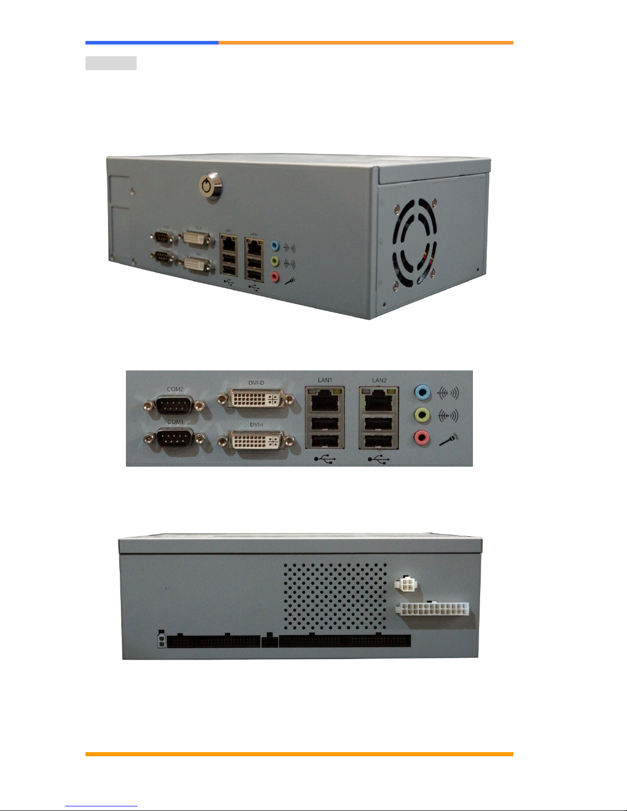
Mechanical
Front I/O
- 1 x DVI, 1 x DVI-D
- 2 x RS-232
- 2 x LAN
- 4 x USB
- 5.1 channel audio
Rear I/O
- 16 x ESD Protected Input; 16 x Photo-coupler Protected Input
- 28 x 500mA current sink output; 4 x 3A current sink output
- 2 x RS-232, 1 x RS-485, 2 x ccTalk, 3 x Simple RS-232(Tx, Rx)
- 8 x Intrusion Detection
■
■
Power Supply
Power input
ATX compliant
Power consumption
TBD
■
■
Software
O/S
Windows XP(e)
Linux
■
■
Mechanical Environment
Environmental
Operating Temperature: 0 –40 ºC (32 ºF –140 ºF)
Storage Temperature: -20 –85 ºC (-4 ºF –185 ºF)
Relative Humidity: 10-85 % RH, non-condensing
Compliant
CE/FCC Class A
GLI
Dimension
270mm (W) x 184mm (D) x mm (H)
■
■
Applications
Main Application
Video slot machines (Class II/III)
Video lottery terminals

AEWIN Technologies Co., Ltd. All rights reserved. Ver1.0 Dec. 2013
9
Amusement game machines
Master unit of roulette machine
Downloadable gaming terminal
Multi player gaming machines
Order Information
Standard
SGA-2210A
AMD T56N Dual Core 1.65GHz based Gaming System with 10x COM, 2x GbE,
2MB NVRAM/MRAM, 2MB Boot ROM and TPM
Optional
DK-GA2210
Development Kit
- R217A Gaming I/O testing board
- 46L-G00010-02 Cable of R217A of GA-2210
- 46L-SATA07-00 S-ATA cable
- 46L-IPS200-00 KB/MS cable
- 46L-IUSB01-00 USB cable
- 46L-COM007-00; COM cable

AEWIN Technologies Co., Ltd. All rights reserved. Ver1.0 Dec. 2013
10
1.3 Precautions
Please make sure you properly ground yourself before handling the GA-2210 board
or other system components. Electrostatic discharge can be easily damage the
GA-2210 board.
Do not remove the anti-static packing until you are ready to install the GA-2210
board.
Ground yourself before removing any system component from it protective
anti-static packaging. To ground yourself, grasp the expansion slot covers or other
unpainted parts of the computer chassis.
Handle the GA-2210 board by its edges and avoid touching its component.

AEWIN Technologies Co., Ltd. All rights reserved. Ver1.0 Dec. 2013
11
1.4 Layout
GA-2210
AEWIN Technologies Co., Ltd. All rights reserved. Ver1.0 Dec. 2013
12
SGA-2210

AEWIN Technologies Co., Ltd. All rights reserved. Ver1.0 Dec. 2013
13
1.5 Dimension
GA-2210
Board Dimension (mm) (Component Side)

AEWIN Technologies Co., Ltd. All rights reserved. Ver1.0 Dec. 2013
14
SGA-2210

AEWIN Technologies Co., Ltd. All rights reserved. Ver1.0 Dec. 2013
15
Chapter 2. Connector and Jumper Settings
Board Connector
Connector List
Connector
Description
Connector
Description

AEWIN Technologies Co., Ltd. All rights reserved. Ver1.0 Dec. 2013
16
CN1
SATA Connector
CN12
Test Pin Header
CN2
SATA Connector
CN13
Audio Connector
CN3
Dual DVI Connector
DVI-D(up); DVI-I(down)
CN14
Audio5.1 Pin Header
CN4
Test Pin Header
CN15
LPC Port80 Pin Header
CN5
Cfast Connector
CN16
COM1/COM2 Connector
CN6
CF Connector
CN17
FPGA Update Pin Header
CN7
RJ45+USB Connector
CN18
None
CN8
RJ45+USB Connector
CN19
Intrusion Battery Connector
CN9
None
CN20
Intrusion Update Pin Header
CN10
USB Pin Header
CN21
GPIO Extend Connector
CN11
PS2 KB/MS Pin Header
CN22
GPO Connector
(OUT0~OUT27 500mA)
CN23
GPI Connector(IN0~IN31)
CN24
GPO Connector
(OUT28~OUT31 2A)
CN25
DOOR Connector
(DOOR0~DOOR6)
CN26
COM Port Connector
(COM3~COM10)
CN27
DCIN Connector(+12V)
CN28
FAN Connector
CN29
ATX 4Pin Connector
CN30
ATX 24Pin Connector
CN31
Power Button/System Reset
Pin Header
CN32
FAN Connector
CN33
FAN Connector
CN34
USB Pin Header
DIMM1
DDR3 Slot
DIMM2
DDR3 Slot
PW1
HDD Power Connector
PCI-E1
PCI-E x16 slot(x4 singel)
JP1
CMOS Hold / Clear Select
JP2
None
JP3
FPGA EEPROM
Write Protect Select
JP4
None
JP5
Intrusion Update Voltage
Select
JP6
DOOR7 Select
JP7
SATA NANDrive
Write Protect Select
Connector/Jumper Setting
CN1/CN2: SATA Connector
Pin
Signal
1
Ground
2
TXP
3
TXN
4
Ground

AEWIN Technologies Co., Ltd. All rights reserved. Ver1.0 Dec. 2013
17
5
RXN
6
RXP
7
Ground
CN3A: DVI Connector (DVI-D)
CN3A
DUAL DVI-I
TMDS Data2-
CK1
TMDS Data2+
CK2
TMDS Data2/4 Shield
CK3
TMDS Data4-
CK4
TMDS Data4+
CK5
DDC Clock
CK6
DDC Data
CK7
A VSYNC
CK8
TMDS Data1-
CK9
TMDS Data1+
CK10
TMDS Data1/3 Shield
CK11
TMDS Data3-
CK12
TMDS Data3+
CK13
+5V Power
CK14
GND(for +5V)
CK15
Hot Plug Detct
CK16
TMDS Data0-
CK17
TMDS Data0+
CK18
TMDS Data0/5 Shield
CK19
TMDS Data5-
CK20
TMDS Data5+
CK21
TMDS Clock Shield
CK22
TMDS Clock+
CK23
TMDS Clock-
CK24
RED
C1
GREEN
C2
BLUE
C3
A HSYNC
C4
AGND
C5
CASE1
M1
CASE2
M2
Pin
Define
Pin
Define
M1
CASE GND
M2
CASE GND
CK1
DP0_TX0_N
CK2
DP0_TX0_P
CK3
GND
CK4
-
CK5
-
CK6
DP0_AUX_P
CK7
DP0_AUX_N
CK8
-
CK9
DP0_TX1_N
CK10
DP0_TX1_P
CK11
GND
CK12
-
CK13
-
CK14
+5V
CK15
GND
CK16
DVID_HPD
CK17
DP0_TX2_N
CK18
DP0_TX2_P
CK19
GND
CK20
-
CK21
-
CK22
GND
CK23
DP0_TX3_N
CK24
DP0_TX3_P
C1
Analog_R
C2
Analog_G
C3
-
C4
-
C5
Analog GND
-
CN3B: DVI Connector (DVI-I)

AEWIN Technologies Co., Ltd. All rights reserved. Ver1.0 Dec. 2013
18
CN3B
DUAL DVI-I
TMDS Data2-
CK25
TMDS Data2+
CK26
TMDS Data2/4 Shield
CK27
TMDS Data4-
CK28
TMDS Data4+
CK29
DDC Clock
CK30
DDC Data
CK31
A VSYNC
CK32
TMDS Data1-
CK33
TMDS Data1+
CK34
TMDS Data1/3 Shield
CK35
TMDS Data3-
CK36
TMDS Data3+
CK37
+5V Power
CK38
GND(for +5V)
CK39
Hot Plug Detct
CK40
TMDS Data0-
CK41
TMDS Data0+
CK42
TMDS Data0/5 Shield
CK43
TMDS Data5-
CK44
TMDS Data5+
CK45
TMDS Clock Shield
CK46
TMDS Clock+
CK47
TMDS Clock-
CK48
RED
C6
GREEN
C7
BLUE
C8
A HSYNC
C9
AGND
C10
CASE1
M3
CASE2
M4
Pin
Define
Pin
Define
M3
CASE GND
M4
CASE GND
CK25
DP1_TX0_N
CK26
DP1_TX0_P
CK27
GND
CK28
-
CK29
-
CK30
DP1_AUX_P
CK31
DP1_AUX_N
CK32
Analog_VSY
CK33
DP1_TX1_N
CK34
DP1_TX1_P
CK35
GND
CK36
-
CK37
-
CK38
+5V
CK39
GND
CK40
DVII_HPD
CK41
DP1_TX2_N
CK42
DP1_TX2_P
CK43
GND
CK44
-
CK45
-
CK46
GND
CK47
DP1_TX3_N
CK48
DP1_TX3_P
C6
Analog_R
C7
Analog_G
C8
Analog_B
C9
Analog_HSY
C10
Analog GND
-
CN5:CFast Connector

AEWIN Technologies Co., Ltd. All rights reserved. Ver1.0 Dec. 2013
19
CN5/6
CFAST SOCKET
GND
S1
RX+
S2
RX-
S3
GND
S4
TX-
S5
TX+
S6
GND
S7
CDI
PC1
GND
PC2
TBD
PC3
TBD
PC4
TBD
PC5
TBD
PC6
GND
PC7
LED1
PC8
LED2
PC9
IO1
PC10
IO2
PC11
IO3
PC12
3.3V
PC13
3.3V
PC14
PGND
PC15
PGND
PC16
CDO
PC17
NC1 NC1
NC2 NC2
NC3 NC3
NC4 NC4
NC5 NC5
NC6 NC6
NC7 NC7
NC8 NC8
Pin
Signal
Pin
Signal
S1
GND
S2
SATA_TX_P
S3
SATA_TX_N
S4
GND
S5
SATA_RX_N
S6
SATA_RX_P
S7
GND
S8
PC1
-
PC2
GND
PC3
Test Pin
PC4
Test Pin
PC5
Test Pin
PC6
Test Pin
PC7
GND
PC8
-
PC9
-
PC10
-
PC11
-
PC12
-
PC13
+3.3V
PC14
+3.3V
PC15
GND
PC16
GND
PC17
-
NC1
-
NC2
-
NC3
-
NC4
-
NC5
-
NC6
-
NC7
-
NC8
-

AEWIN Technologies Co., Ltd. All rights reserved. Ver1.0 Dec. 2013
20
CN6:CF Connector
Pin
Define
Pin
Define
1
GND
26
CF_CD-1
2
IDE_PDD3
27
IDE_PDD11
3
IDE_PDD4
28
IDE_PDD12
4
IDE_PDD5
29
IDE_PDD13
5
IDE_PDD6
30
IDE_PDD14
6
IDE_PDD7
31
IDE_PDD15
7
IDE_PDCS1_N
32
IDE_PDCS3_N
8
GND
33
GND
9
GND
34
IDE_PDIOR_N
10
GND
35
IDE_PDIOW_N
11
GND
36
CF_PIN36
12
GND
37
IDE_IRQ
13
+5V
38
+5V
14
GND
39
GND
15
GND
40
NC
16
GND
41
IDE_RST_N
17
GND
42
IDE_PDIORDY
18
IDE_PDA2
43
IDE_PDDREQ
19
IDE_PDA1
44
IDE_PDDACK_N
20
IDE_PDA0
45
IDE_ACTP_N
21
IDE_PDD0
46
IDE_PDIAG_N
22
IDE_PDD1
47
IDE_PDD8
23
IDE_PDD2
48
IDE_PDD9
24
IDE_CS16_N
49
IDE_PDD10
25
NC
50
GND
CN7/CN8:USB and LAN RJ45
Pin
Signal
Pin
Signal
15
5VUSB
1
NC
16
USBDT-
2
MDIP0
17
USBDT+
3
MDIN0
Table of contents


