Afar NX-2E1/T1 User manual

NetCrossing Gateway NX-2E1/T1
Operator’s Manual
September 2009
AFAR Communications Inc.
81 David Love Place
Santa Barbara, CA 93117
Tel: +1 805 681 1993
Fax: +1 805 681 1994
go the distance


NetCrossing Gateway NX-2E1/T1
Operator’s Manual
September 2009
AFAR Communications Inc.
81 David Love Place
Santa Barbara, CA 93117
Tel: +1 805 681 1993
Fax: +1 805 681 1994
$25.00


NetCrossing Gateway NX-2E1/T1 Operator’s Manual
i -
Customer Service
AFAR provides customer service during normal Pacific Coast business hours and may be reached by
voice, fax, or email as follows:
Tel: +1 805 681 1993
Fax: +1 805 681 1994
email: [email protected]
If you must return the equipment, please contact us for a Return Material Authorization (RMA)
number. Equipment should be shipped to:
AFAR Communications Inc.
81 David Love Place,
Santa Barbara, CA 93117
U.S.A.

NetCrossing Gateway NX-2E1/T1 Operator’s Manual
ii
STATEMENT OF WARRANTY
Afar Communications Inc. products, except as otherwise stated in an applicable price list, are warranted against
defects in workmanship and material for a period of one (1) year from date of delivery as evidenced by Afar
Communications Inc.’s packing slip or other transportation receipt.
Afar Communications Inc.’s sole responsibility under this warranty shall be to either repair or replace, at its
option, any component which fails during the applicable warranty period because of a defect in workmanship
and material, provided purchaser has promptly reported same to Afar Communications Inc. in writing. All
replaced products or parts shall become Afar Communications Inc.’s property.
Afar Communications Inc. shall honor this warranty at its facility in Goleta, California. It is purchaser’s
responsibility to return, at its expense, the defective Product to Afar Communications Inc. Purchaser must
notify Afar Communications Inc. and obtain shipping instructions prior to returning any product. Afar
Communications Inc. will pay the transportation charges for the return of the Product to purchaser but not
including any custom clearance fees and other related charges which shall be paid by purchaser. If Afar
Communications Inc. determines that the Product is not defective within the terms of the warranty, purchaser
shall pay Afar Communications Inc. all costs of handling, transportation and repairs at the prevailing repair
rates.
All the above warranties are contingent upon proper use of the Product. These warranties will not apply (i) if
adjustment, repair, or parts replacement is required because of accident, unusual physical, electrical or
electromagnetic stress, negligence, misuse, failure of electric power environmental controls, transportation, or
abuses other than ordinary use (ii) if the Product has been modified or has been repaired or altered outside Afar
Communications Inc.’s factory, unless Afar Communications Inc. specifically authorizes such repairs or
alterations; (iii) where Afar Communications Inc. serial numbers, or quality assurance decals have been
removed or altered.
Afar Communications Inc. reserves the right to make product improvements without incurring any obligation or
liability to make the same changes in Products previously manufactured or purchased.
No person, including any dealer, agent or representative of Afar Communications Inc. is authorized to assume
for Afar Communications Inc. any other liability on its behalf except as set forth herein. Afar Communications
Inc. hereby disclaims all implied warranties of products including without limitation, all implied warranties of
merchantability or fitness for a particular purpose. The warranties expressly stated herein are the sole
obligation or liability on the part of Afar Communications Inc. arising out of or in connection with the sale or
performance of the products.
In no event will Afar Communications Inc. be liable to purchaser for (i) procurement costs; (ii) special,
indirect or consequential damages; (iii) any damages resulting from loss of use, data or profits arising out of the
use of Afar Communications Inc. products. In no event shall Afar Communications Inc. be liable for any
breach of warranty in an amount exceeding the net selling price of any defective Product.

NetCrossing Gateway NX-2E1/T1 Operator’s Manual
iii -
FCC Notice
This equipment has been tested and found to comply with the limits for a Class B
digital device, pursuant to Part 15 of the FCC Rules. These limits are designed to
provide reasonable protection against harmful interference in a residential
installation. This equipment generates, uses, and can radiate radio frequency
energy and, if not installed and used in accordance with the instructions, may cause
harmful interference to radio communications. However, there is no guarantee that
interference will not occur in a particular installation. If this equipment does cause
harmful interference to radio or television reception, which can be determined by
turning the equipment off and on, the user is encouraged to try to correct the
interference by one or more of the following measures:
• Reorient or relocate the receiving antenna.
• Increase the separation between the equipment and receiver.
• Connect the equipment into an outlet on a circuit different from that to which
the receiver is connected.
• Consult the dealer or an experienced radio/TV technician for help.
Changes or modifications not expressly approved in writing by AFAR
Communications Inc. may void the user’s authority to operate this equipment. AFAR
Communications Inc. can not accept any financial or other responsibilities that may
be the result of your use of this information, including direct, indirect, special, or
consequential damages. Refer to warranty documents for product warranty
coverage and specifics.

NetCrossing Gateway NX-2E1/T1 Operator’s Manual
iv

NetCrossing Gateway NX-2E1/T1 Operator’s Manual
v -
TABLE OF CONTENTS
1 PRODUCT DESCRIPTION................................................................................................................... 1-1
1.1 OVERVIEW ............................................................................................................................................. 1-1
1.2 FRONT PANEL ........................................................................................................................................ 1-3
1.3 REAR PANEL .......................................................................................................................................... 1-5
2 THEORY OF OPERATION .................................................................................................................. 2-1
2.1 WIDE AREA NETWORK (WAN) ............................................................................................................. 2-1
2.2 LAN PORT ............................................................................................................................................. 2-1
2.3 SERIAL (TDM) PORTS............................................................................................................................ 2-2
2.3.1 Connection Setup.......................................................................................................................... 2-2
2.3.2 Serial Data Encapsulation............................................................................................................ 2-3
2.3.3 Jitter Buffer and Link Latency ...................................................................................................... 2-5
2.3.4 Clock Sources ............................................................................................................................... 2-6
2.4 SYNCHRONIZATION PORT....................................................................................................................... 2-8
3 UNIT CHECKOUT AND FIRMWARE UPGRADES......................................................................... 3-1
3.1 BENCH CHECK OUT ............................................................................................................................... 3-1
3.2 UPGRADING THE FIRMWARE. ................................................................................................................. 3-2
3.2.1 Description ................................................................................................................................... 3-2
3.2.2 Installing new firmware through the Ethernet port ...................................................................... 3-3
3.2.3 Installing new firmware using Telnet ........................................................................................... 3-4
3.2.4 Installing new firmware using the RS-232 serial port .................................................................. 3-5
3.2.5 Feature upgrades.......................................................................................................................... 3-7
4 COMMANDS........................................................................................................................................... 4-1
4.1 CONFIGURATION TECHNIQUES ............................................................................................................... 4-1
4.2 COMMAND SYNTAX................................................................................................................................4-1
4.3 CONFIGURATION MANAGEMENT COMMANDS........................................................................................ 4-3
4.4 MAJOR CONFIGURATION PARAMETERS.................................................................................................. 4-5
4.5 INTERNET PROTOCOL (IP) MANAGEMENT COMMANDS ....................................................................... 4-12
4.6 INSTALLATION AND MONITORING COMMANDS.................................................................................... 4-14
4.7 FILE UTILITIES ..................................................................................................................................... 4-16
4.8 EVENT LOGGING COMMANDS .............................................................................................................. 4-18
4.9 MISCELLANEOUS COMMANDS .............................................................................................................. 4-19
5 NETWORK MANAGEMENT............................................................................................................... 5-1
5.1 TELNET .................................................................................................................................................. 5-1
5.1.1 General......................................................................................................................................... 5-1
5.1.2 Starting a Telnet Session .............................................................................................................. 5-1
5.1.3 Telnet Security .............................................................................................................................. 5-2
5.2 SNMP.................................................................................................................................................... 5-2
5.2.1 Command Line Interface Versus SNMP ....................................................................................... 5-2
5.2.2 What is SNMP?............................................................................................................................. 5-3
5.2.3 Security Considerations in SNMP ................................................................................................ 5-3
5.2.4 Examples of Network Management Systems................................................................................. 5-4
5.2.5 NetCrossing Gateway Management Information Base (MIB)...................................................... 5-4
APPENDIX A – COMMAND SUMMARY .................................................................................................. A-1
APPENDIX B - SPECIFICATIONS...............................................................................................................B-1
APPENDIX C – ETHERNET CONSOLE PROGRAM .............................................................................. C-1
APPENDIX D – QUICK SETUP ................................................................................................................... D-1

NetCrossing Gateway NX-2E1/T1 Operator’s Manual
vi

NetCrossing Gateway NX-2E1/T1 Operator’s Manual
1-1
1PRODUCT DESCRIPTION
1.1 Overview
The Afar NetCrossing™ Gateway (NX-2E1/T1) allows you to establish a serial synchronous (E1 or
T1) link across a packet switch network. The gateway breaks the continuous serial data stream into
fixed size packets, adds the Ethernet or IP framing, and sends them over the packet switch network to
a remote gateway. At the remote end, the gateway removes the Ethernet or IP framing and
reconstructs the original data stream. The gateways regenerate the clocks and keep both ends
synchronized with no bit slips.
The receiving NetCrossing™ gateway buffers a number of incoming packets in order to compensate
for the packet delivery jitter introduced by the network. The size of this buffer is configurable to
accommodate different amounts of expected jitter. The gateways collect statistics of the network
jitter, and can automatically optimize the buffer size for minimal link latency.
Ethernet
LAN
LAN
E1 / T1
PBX,
MUX,.. netX Gateway
netX Gateway
E1 / T1
PBX,
MUX,..
Figure 1.1 – NetCrossing Gateway Typical Application
The NX-2E1/T1 supports up to two independent full E1 or T1 Time Division Multiplex (TDM) bit
streams. You may operate the serial TDM ports in totally transparent mode or in fractional mode. In
fractional mode the NetCrossing Gateway extracts user specified time slots from the input serial
stream and transmits only those bits. At the receiving end the peer gateway reconstructs the E1 or T1
frames, filling in the absent slots with a configurable idle pattern.
If the application is to cross a single Ethernet network, the gateways create packets using simple and
very efficient SNAP encapsulation. Or you may configure the units to perform full IP/UDP
encapsulation, which allows crossing multiple networks.
When crossing a single network the gateways can automatically scout for an unconnected peer and
establish a point-to-point connection with minimal configuration required. Configuration and
monitoring is performed using a terminal connected to a front panel console port or through the LAN
port using Telnet, SNMP or the Afar Ethernet Console program.
NetCrossing Gateway NX-2E1/T1 Operator’s Manual
1-2
In addition to the serial TDM data streams, the gateways include a user LAN Ethernet port. This port
implements a transparent learning bridge which only forwards to the network the packets addressed to
stations that are not in the local LAN. You can set a limit on the cumulative throughput offered to the
network. In this case the gateway gives priority to the serial TDM data and allocates to the user LAN
the remaining bandwidth. This is useful if the network port has a throughput limitation imposed by,
for example, a radio link.
For wireless applications the NetCrossing™ gateway is designed to work seamlessly with the Afar
Wireless Ethernet radios. The gateway provides data, control and power to the radio through a single
CAT5 cable. The radio is enclosed in a waterproof enclosure allowing outdoor deployment for
improved system performance. In addition, if your application requires multiple wireless links
emanating from the same location, the NetCrossing™ gateways can synchronize the transmissions of
all the radios such that they do not cause self-interference. This is achieved by simply daisy chaining
the SYNC ports of all of the NetCrossing™ gateways. Refer to the Afar Radio literature for more
information on this feature.
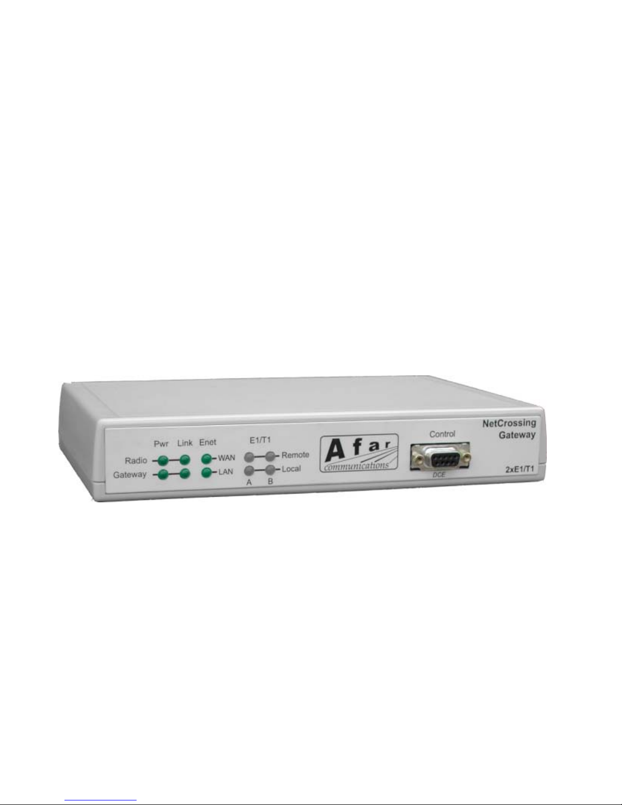
The NetCrossing Gateway is housed in a tabletop plastic enclosure (see Figure 1.2). It is shipped
with an external universal power supply that converts 100-240 VAC into the DC voltage required by
the gateway.
Figure 1.2 - NetCrossing Gateway NX-2E1/T1 front view

NetCrossing Gateway NX-2E1/T1 Operator’s Manual
1-3
1.2 Front Panel
Figure 1.2 shows the NetCrossing Gateway front panel. It includes ten LEDs described in table 1.2
and one DB9 female connector. This connector provides an RS-232 asynchronous port used for
maintenance and initial configuration. This connector is wired as a DCE per table 1.1.
Table 1.1 – Console Port Connector (DB9) Pin Assignments
Pin Signal Name Abbr. Direction
2 Receive Data RD Gateway to DTE
3 Transmit Data TD DTE to Gateway
5 Ground GND

NetCrossing Gateway NX-2E1/T1 Operator’s Manual
1-4
Table 1.2 – Front Panel LEDs
LED Function
Gateway/
Power
Indicates that there is DC power applied to the unit.
Radio/
Power
Indicates that there is current being drawn by the radio connected to the WAN/Radio
connector.
Gateway/
Link
“OFF”: There are no serial links between this and other gateways specified or enabled.
“RED”: One or more of the serial links that have been enabled is not established.
“AMBER”: All enabled links are established, but an error has been detected in any of
the links.
“GREEN”: All enabled links are established; no errors have been detected.
“Steady Blink ON/OFF”: A serial link to another gateway has just been established
and the gateways are measuring and adapting to the jitter in the network.
“Momentary Blink”: Every time that an error is detected the LED will go momentarily
OFF
Radio/
Link
If the wide area network connecting the two gateways consists of a radio link using the
AFAR radios, this LED indicates the state of the associated radio as follows:
”OFF”: The gateway has no communications with the local radio
“2 second off/ blink ON”: the associated radio is in auto SYNC mode and waiting for
a transmission from a peer radio or for an sync message (heartbeat) from the gateway.
“Half second blink ON/OFF”: The associated radio has a heartbeat and is transmitting.
However it has not yet received a reply from a peer radio.
“Steady ON”: The radio has found a peer and an RF link is established between the
two radios.
Ethernet/
LAN
Indicates that there is an Ethernet connection on the LAN port. The LED blinks for
each packet received.
Ethernet/
WAN
Indicates that there is an Ethernet connection on the WAN port.
E1/T1
Local
OFF: This TDM serial port is disabled
RED: The serial port is enabled but no signal is detected at its Rx Line (red alarm)
AMBER: The gateway is detecting an alarm in this TDM Rx line
GREEN: The TDM Rx line is active with no alarms.
E1/T1
Remote
OFF: There is no connection with a remote device for this serial port
RED: The remote gateway is reporting a red alarm (no signal) in its input line.
AMBER: The remote gateway is reporting an alarm in its TDM Rx line
GREEN: The remote gateway is reporting no alarms in its TDM Rx line

NetCrossing Gateway NX-2E1/T1 Operator’s Manual
1-5
1.3 Rear Panel
Figure 1.3 shows the NetCrossing Gateway NX-2E1/T1-B (balanced) rear panel. Figure 1.4 shows
the NetCrossing Gateway NX-2E1/T1-U (unbalanced) rear panel. The panel connectors are described
in Table 1.3
WARNING
The RJ45 connector labeled “Radio” may include DC voltage in two of the pins. It must not be
connected to a LAN as this voltage may damage some LAN cards.
LAN E1/T1 Ground WAN Sync Power
Radio Switch
AB
Figure 1.3 - NetCrossing Gateway NX-2E1/T1-B Rear Panel
LAN E1/T1 Ground WAN Sync Power
Radio Switch
AB
Rx Tx Rx Tx
Figure 1.4 - NetCrossing Gateway NX-2E1/T1-U Rear Panel

NetCrossing Gateway NX-2E1/T1 Operator’s Manual
1-6
Table 1.3 – Rear Panel Connectors
Connector Type Function
LAN RJ45 10 BaseT Ethernet connection to your “Local Area Network”. It runs at
10 MHz half or full duplex. See table 1.5 for the pin assignments. The
gateway “bridges” this LAN port to the WAN port.
E1/T1 RJ45
BNC
(NX-2E1/T1-B model) each of the two RJ45 connectors includes pins
for a balanced E1 or T1 serial stream. The wiring of these connectors is
shown in Table 1.4.
(NX-2E1/T1-U model) each unbalanced E1 serial port consists of a pair
of BNC connectors, one for the Transmit and the other for the Receive
signal.
GND Ground connection used for surge suppression. We recommend that you
connect this to an Earth Ground in order to reduce the possibility of
damage to the unit due to transients on external lines
WAN
Radio
WAN
Switch
RJ45
RJ45
10/100 Base T Ethernet connection to the “Wide Area Network”. If you
are connecting the Gateway to an AFAR Radio use the connector labeled
“Radio”. This connector includes voltage to power the radio directly
(see table 1.6). In all other cases use the connector labeled “Switch”
(table 1.5)
SYNC RCA Synchronization signal used to synchronize multiple AFAR radios, each
one connected to its Gateway.
Power Switchcraft DC Voltage to power up the gateway and optionally one AFAR radio
through the WAN/Radio connector.

NetCrossing Gateway NX-2E1/T1 Operator’s Manual
1-7
Table 1.4 – “E1/T1” RJ45 Pin Assignments
Pin Signal Name Direction
1 Rx RING Network to Gateway
2 Rx TIP Network to Gateway
3 (not connected)
4 Tx RING Gateway to Network
5 Tx TIP Gateway to Network
6 (not connected)
7 (not connected)
8 (not connected)
Table1 1.5 – “LAN” and “WAN/Switch” Ethernet Connector Pin Assignments
Pin Signal Name Abbr. Direction
1 Ethernet Tx Tx (+) Gateway to Ethernet
2 Ethernet Tx Tx (-) Gateway to Ethernet
3 Ethernet Rx Rx (+) Ethernet to Gateway
4 (not connected)
5 (not connected)
6 Ethernet Rx Rx (-) Ethernet to gateway
7 (not connected)
8 (not connected)

NetCrossing Gateway NX-2E1/T1 Operator’s Manual
1-8
Table 1.6 – “WAN/Radio” Ethernet Connector Pin Assignments
Pin Signal Name Abbr. Direction
1 Ethernet Tx Tx (+) Radio to Gateway
2 Ethernet Tx Tx (-) Radio to Gateway
3 Ethernet Rx Rx (+) Gateway to Radio
4 VDC DCV (+) Gateway to Radio
5 VDC DCV (+) Gateway to Radio
6 Ethernet Rx Rx (-) Gateway to Radio
7 Ground GND(-)
8 Ground GND(-)

NetCrossing Gateway NX-2E1/T1 Operator’s Manual
2-1
2THEORY OF OPERATION
The NetCrosing Gateway 2E1/T1 models includes three User ports: one to connect to an Ethernet
Local Area Network (LAN), and the other two (E1/T1) to connect to up to two Serial Time Division
Multiplexed (TDM) devices. The gateway processes the LAN and TDM data differently, but in
general, data from all three ports is sent to the Ethernet Wide Area Network (WAN) port.
Conversely, data received in the WAN port is processed by the gateway and sent to the LAN or the
TDM ports as appropriate.
2.1 Wide Area Network (WAN)
The Gateway WAN port is connected to a “Wide Area Network”, through which the gateway can
reach other gateways. The type of WAN network connecting the various gateways is an important
parameter and should be configured accordingly.
If the WAN network consists of a single Ethernet, possibly including Ethernet Bridges, the network
type is classified as a bridge network. In this case the gateways can reach each other by sending
packets addressed to the other gateway physical address. This physical address corresponds to the
unit serial number, which is pre-configured at the factory.
If the WAN network includes Internet Protocol (IP) routers that switch IP packets to their final
destination, the network type is a route network. In this case each gateway must be configured with
its own IP address and the gateways send the packets to each other’s IP addresses. In a routed
network the gateways execute the Address Resolution Protocol (ARP) to translate the destination IP
address into the physical address of the first router in the path.
The route network is the most generic and you can always operate a bridge network in route mode.
However, in bridge mode the packet overhead is considerably smaller. This translates into higher
effective throughput which may be important if the WAN network connecting the gateways is
limited.
2.2 LAN Port
The Local Area Network (LAN) port can be connected to a user LAN or directly to the Ethernet port
of a PC. The gateway implements a self learning “bridging” algorithm that transfers the Ethernet
packets, as appropriate, between the LAN and the WAN ports.
Both ethernet ports are configured in “promiscuous” mode, i.e., the gateway examines all the Ethernet
packets present in either port. Since these Ethernet packets contain a “source” and “destination”
address, the gateway quickly learns the addresses of all the stations that are directly reachable in each
network (all the “source” addresses of packets flowing in that port are reachable).
With this information on hand, the gateway examines the destination address of every Ethernet packet
received and makes one of the following decisions:

NetCrossing Gateway NX-2E1/T1 Operator’s Manual
2-2
1. If the destination address is the gateway own physical address accept and process the packet.
2. If the destination address is for a station that is reachable in that port, discard the packet.
3. If the destination address is the reachable on the opposite port or is unknown, queue that packet to
be sent on the opposite port.
The gateway has capacity to store 500 entries in the Ethernet table. Entries are erased after a certain
amount of time to allow for stations to be moved and not show up in two distinct networks. You can
control this time-out with the bridge command. If the table ever gets full, entries that have been least
used are erased to make room for new entries. You can use the show ethernet command to display
the current list of stations known by the gateway.
The NetCrossing Gateway places the bridged packets from the LAN into a queue. Packets from this
queue are then transmitted into the WAN, but in a controlled fashion such that they never delay the
TDM traffic. Once in the WAN however, the combined traffic from the two TDM ports and the LAN
port might exceed the WAN capacity. If the equipment between the two gateways (bridges or routers
in the WAN) does not distinguish between the LAN and TDM traffic, it will discard packets
indiscriminately. Therefore a burst of LAN traffic could cause errors in the TDM links.
The NetCrossing gateway provides two mechanisms to prevent against such data loss. In a route
network using IP encapsulation you can specify the type-of-service for the TDM packets (using the
udp command). This will tell any routers on the WAN to give priority to the TDM traffic over the
LAN traffic. The second mechanism is to specify a maximum WAN capacity (with the wan
command). In this case the gateway will meter the traffic from the LAN such that the combined
throughput from the TDM and LAN ports never exceeds the specified WAN capacity.
Note that AFAR Radios distinguish between the Gateway LAN and TDM packets. If the offered
traffic exceeds the radio link capacity, the radios delay, and if necessary discard, the LAN packets
before affecting the TDM packets. Therefore, when using the AFAR Radios you do not need to use
the wan capacity parameter to prevent serial data loss.
2.3 Serial (TDM) Ports
The serial TDM ports carry continuous synchronous data streams. Unlike Ethernet traffic, this type
of data is “connection oriented”, i.e. the user serial device gets a “permanent” link to another serial
device that is connected to a remote gateway elsewhere in the WAN. You can establish this point to
point connection between any two gateways connected to the same WAN. Once the connection is
established the serial synchronous data flows continuously between your two serial devices as if they
were connected by wire.
2.3.1 Connection Setup
You must specify the remote peer gateway so that a connection setup can be initiated. If the wan
network type is set to bridge, the peer is specified as the serial number of the of the unit with which
you wish to connect (use the wan command). If the wan network type is set to route, the peer is
specified as the remote unit IP address using the udp command.
A gateway with an assigned peer sends, once a second, a connect request packet addressed to that
peer. This connect request packet contains the serial port of the gateway requesting the connection.
This manual suits for next models
2
Table of contents
Popular Gateway manuals by other brands


D-Link
D-Link DPN-144DG user manual

Ingics
Ingics iGS01S user manual

Weishaupt
Weishaupt WEM-KNX Installation and operating manual

Opengear
Opengear ACM7008-2-LMx series quick start guide

Ericsson
Ericsson EDACS Data Advantage Series Installation and Maintenance

Asyst Technologies
Asyst Technologies Advantag 9100 Technical manual

Pepperl+Fuchs
Pepperl+Fuchs VBG-PN-K20-D-BV Installation instruction

RTA
RTA 460TCP-N2E Product user guide

Micro control systems
Micro control systems MCS-BMS-GATEWAY Startup guide

Seeed
Seeed SENSECAP user guide

Sierra Wireless
Sierra Wireless AirLink GX400 user guide

NetComm Wireless
NetComm Wireless NF18ACV Faqs