Afar AR-9010E User manual

pulsAR Wireless Ethernet Bridge
Operator’s Manual
Models: AR-9010E
AR-9027E
AR-24010E
AR-24027E
AR-24110E
June 2015
AFAR Communications Inc.
81 David Love Place
Santa Barbara, CA 93117
Tel: +1 805 81 1993
Fax: +1 805 81 1994
go the distance


pulsAR Wireless Ethernet Bridge
Operator’s Manual
Models: AR-9010E
AR-9027E
AR-24010E
AR-24027E
AR-24110E
June 2015
AFAR Communications Inc.
81 David Love Place
Santa Barbara, CA 93117
Tel: +1 805 81 1993
Fax: +1 805 81 1994
$25.00

pulsAR radio Operator's Manual
Customer Service
AFAR provides customer service during normal U.S. Pacific Coast business hours and may be reached by
voice, fax, or email as follows:
Tel: +1 805 81 1993
Fax: +1 805 81 1994
email: [email protected]
If you must return the equipment, please contact us for a Return Material Authorization (RMA) number.
Equipment should be shipped to:
AFAR Communications Inc.
81 David Love Place,
Santa Barbara, CA 93117
U.S.A.
i

pulsAR radio Operator's Manual
STATEMENT OF WARRANTY
Afar Communications Inc. products, except as otherwise stated in an applicable price list, are warranted against
defects in workmanship and material for a period of one (1) year from date of delivery as evidenced by Afar
Communications Inc.’s packing slip or other transportation receipt.
Afar Communications Inc.’s sole responsibility under this warranty shall be to either repair or replace, at its
option, any component which fails during the applicable warranty period because of a defect in workmanship
and material, provided purchaser has promptly reported same to Afar Communications Inc. in writing. All
replaced products or parts shall become Afar Communications Inc.’s property.
Afar Communications Inc. shall honor this warranty at its facility in Goleta, California. It is purchaser’s
responsibility to return, at its expense, the defective Product to Afar Communications Inc. Purchaser must
notify Afar Communications Inc. and obtain shipping instructions prior to returning any product. Afar
Communications Inc. will pay the transportation charges for the return of the Product to purchaser but not
including any custom clearance fees and other related charges which shall be paid by purchaser. If Afar
Communications Inc. determines that the Product is not defective within the terms of the warranty, purchaser
shall pay Afar Communications Inc. all costs of handling, transportation and repairs at the prevailing repair
rates.
All the above warranties are contingent upon proper use of the Product. These warranties will not apply (i) if
adjustment, repair, or parts replacement is required because of accident, unusual physical, electrical or
electromagnetic stress, negligence, misuse, failure of electric power environmental controls, transportation, or
abuses other than ordinary use (ii) if the Product has been modified or has been repaired or altered outside Afar
Communications Inc.’s factory, unless Afar Communications Inc. specifically authorizes such repairs or
alterations; (iii) where Afar Communications Inc. serial numbers, or quality assurance decals have been
removed or altered.
Afar Communications Inc. reserves the right to make product improvements without incurring any obligation or
liability to make the same changes in Products previously manufactured or purchased.
No person, including any dealer, agent or representative of Afar Communications Inc. is authorized to assume
for Afar Communications Inc. any other liability on its behalf except as set forth herein. Afar Communications
Inc. hereby disclaims all implied warranties of products including without limitation, all implied warranties of
merchantability or fitness for a particular purpose. The warranties expressly stated herein are the sole
obligation or liability on the part of Afar Communications Inc. arising out of or in connection with the sale or
performance of the products.
In no event will Afar Communications Inc. be liable to purchaser for (i) procurement costs; (ii) special,
indirect or consequential damages; (iii) any damages resulting from loss of use, data or profits arising out of the
use of Afar Communications Inc. products. In no event shall Afar Communications Inc. be liable for any
breach of warranty in an amount exceeding the net selling price of any defective Product.
ii

pulsAR radio Operator's Manual
F Notice
This device complies with part 15 of the F Rules. Operation is subject to the
following two conditions: (1) This device may not cause harmful interference, and
(2) this device must accept any interference received, including interference that
may cause undesired operation.
This equipment has been tested and found to comply with the limits for a Class B digital
device, pursuant to Part 15 of the FCC ules. These limits are designed to provide
reasonable protection against harmful interference in a residential installation. This
equipment generates, uses, and can radiate radio frequency energy and, if not installed
and used in accordance with the instructions, may cause harmful interference to radio
communications. However, there is no guarantee that interference will not occur in a
particular installation. If this equipment does cause harmful interference to radio or
television reception, which can be determined by turning the equipment off and on, the
user is encouraged to try to correct the interference by one or more of the following
measures:
• eorient or relocate the receiving antenna.
• Increase the separation between the equipment and receiver.
• Connect the equipment into an outlet on a circuit different from that to which the
receiver is connected.
• Consult the dealer or an experienced radio/TV technician for help.
Changes or modifications not expressly approved in writing by AFA Communications
Inc. may void the user’s authority to operate this equipment. AFA Communications
Inc. can not accept any financial or other responsibilities that may be the result of your
use of this information, including direct, indirect, special, or consequential damages.
efer to warranty documents for product warranty coverage and specifics.
Industry of anada Notice
These devices have been designed to operate with two antennas each, listed on page
3-6, and having a maximum gain of 15 dBi at 900 MHz, or 24 dBi at 2.4 GHz. Antennas
having a gain greater than the values above are strictly prohibited for use with these
devices. The required antenna impedance is 50 ohms.
Operation is subject to the following two conditions: (1) this device may not cause
interference, and (2) this device must accept any interference, including interference
that may cause undesired operation of the device.
To reduce potential radio interference to other users, the antenna type and its gain
should be so chosen that the equivalent isotropically radiated power (e.i.r.p.) is not
more than that permitted for successful communication.
iii

pulsAR radio Operator's Manual
TABLE OF CONTENTS
PRODUCT DESCRIPTION............................................................................................. -
1.1 RADIO OVERVIEW.........................................................................................................................................1-1
1.2 RADIO COMPONENTS....................................................................................................................................1-2
1.3 RADIO CONNECTORS.....................................................................................................................................1-3
1.4 RADIO POWER..............................................................................................................................................1-4
1.5 OUTDOOR INTERCONNECT CABLE..................................................................................................................1-
2 NETWORK TOPOLOGIES AND APPLICATIONS ..................................................2-
2.1 NETWORK TOPOLOGIES.................................................................................................................................2-1
2.1.1 Point to point ......................................................................................................................................2-2
2.1.2 Point to Multipoint .............................................................................................................................2-2
2.1.3 Tree topology......................................................................................................................................2-3
2.1.4 Linear Networ ...................................................................................................................................2-4
2.1.5 Loop Topology....................................................................................................................................2-5
2.2 ROAMING.....................................................................................................................................................2-5
2.2.1 Operation............................................................................................................................................2-5
2.2.2 Roaming branches...............................................................................................................................2-6
2.2.3 Fast roaming.......................................................................................................................................2-6
2.2.4 Roam change hub criteria...................................................................................................................2-7
2.2.5 Redundant RF paths............................................................................................................................2-7
2.2.6 Redundant hub operation: .................................................................................................................2-7
2.3 TIME DIVISION DUPLEX................................................................................................................................2-7
2.3.1 Fixed and variable cycle split.............................................................................................................2-7
2.3.2 On demand bandwidth allocation.......................................................................................................2-8
2.4 RADIO CO-LOCATION AND INTERFERENCE......................................................................................................2-8
2.4.1 Radio co-location ...............................................................................................................................2-8
2.4.2 Co-located radios self-interference.....................................................................................................2-9
2.4.3 SPAN Networ synchronization........................................................................................................2-10
2.4.4 Heartbeat suppression......................................................................................................................2-12
2.4.5 Synchronization with NetCrossing Gateways...................................................................................2-12
2.5 ETHERNET BRIDGING..................................................................................................................................2-14
2.5.1 Self-learning bridging.......................................................................................................................2-14
2.5.2 Pac et priorities................................................................................................................................2-14
2. ENCRYPTION...............................................................................................................................................2-15
3 INSTALLATION AND SETUP ......................................................................................3-
3.1 BENCH CHECK OUT .....................................................................................................................................3-1
3.1.1 Using the radio Ethernet connection..................................................................................................3-1
3.1.2 Using the radio auxiliary port.............................................................................................................3-2
3.2 FIELD INSTALLATION....................................................................................................................................3-3
3.2.1 Mounting Brac et installation.............................................................................................................3-3
3.2.2 Earth Grounding.................................................................................................................................3-4
3.2.3 Power/Ethernet cable..........................................................................................................................3-6
3.2.4 Antenna Installation............................................................................................................................3-6
3.2.5 Antenna Alignment..............................................................................................................................3-7
3.2.6 Radio Configuration............................................................................................................................3-8
3.2.7 Spectrum Analysis and channel selection...........................................................................................3-9
3.2.8 Output Power Limits (FCC)..............................................................................................................3-10
3.2.9 Output Power Limits (CE) ...............................................................................................................3-10
3.2.10 Maximum Permissible Exposure (MPE) Limitations......................................................................3-11
3.3 RECORDING THE NETWORK CONFIGURATION AND PERFORMANCE................................................................3-12
3.4 UPGRADING THE FIRMWARE........................................................................................................................3-12
3.4.1 Description........................................................................................................................................3-12
iv

pulsAR radio Operator's Manual
3.4.2 Installing new firmware through the Ethernet port..........................................................................3-13
3.4.3 Installing new firmware using Telnet................................................................................................3-15
3.4.4 Installing new firmware using the RS-232 serial port......................................................................3-16
3.4.5 Feature upgrades..............................................................................................................................3-18
4 COMMANDS.....................................................................................................................4-
4.1 CONFIGURATION TECHNIQUES........................................................................................................................4-1
4.2 COMMAND SYNTAX.......................................................................................................................................4-2
4.3 CONFIGURATION MANAGEMENT COMMANDS.................................................................................................4-3
4.4 MAJOR CONFIGURATION PARAMETERS..........................................................................................................4-
4.5 INTERNET PROTOCOL (IP) MANAGEMENT COMMANDS.................................................................................4-13
4. INSTALLATION AND LINK MONITORING COMMANDS....................................................................................4-15
4.7 FILE UTILITIES............................................................................................................................................4-20
4.8 EVENT LOGGING COMMANDS......................................................................................................................4-22
4.9 MISCELLANEOUS COMMANDS......................................................................................................................4-24
5 NETWORK MANAGEMENT.........................................................................................5-
5.1 TELNET........................................................................................................................................................5-1
5.1.1 General................................................................................................................................................5-1
5.1.2 Starting a Telnet Session.....................................................................................................................5-1
5.1.3 Telnet Security.....................................................................................................................................5-2
5.2 SNMP.........................................................................................................................................................5-2
5.2.1 Command Line Interface Versus SNMP.............................................................................................5-2
5.2.2 What is SNMP?...................................................................................................................................5-3
5.2.3 Security Considerations in SNMP.......................................................................................................5-3
5.2.4 Examples of Networ Management Systems.......................................................................................5-3
5.2.5 pulsAR radio Management Information Base (MIB)..........................................................................5-4
5.3 UDP COMMAND AND DATA INTERFACE........................................................................................................5-4
5.3.1 Purpose...............................................................................................................................................5-4
5.3.2 UDP Command Pac et formats..........................................................................................................5-5
6 RF LINK DESIGN............................................................................................................6-
.1 ANTENNA SELECTION................................................................................................................................... -1
.2 RF PATH ANALYSIS...................................................................................................................................... -2
6.2.1 Line-of-Sight Requirements.................................................................................................................6-2
6.2.2 Earth curvature...................................................................................................................................6-4
6.2.3 Fresnel Zone........................................................................................................................................6-4
6.2.4 Atmospheric Refraction.......................................................................................................................6-5
6.2.5 Clearing Obstructions.........................................................................................................................6-5
.3 RF LINK BUDGET CALCULATIONS................................................................................................................. -
APPENDIX A – COMMAND SUMMARY.....................................................................A-
APPENDIX B – SPECIFICATIONS................................................................................B-
APPENDIX C – CHANNEL FREQUENCIES................................................................C-
APPENDIX D – CABLE DIAGRAMS.............................................................................D-
APPENDIX E – QUICK SETUP EXAMPLES................................................................E-
v

pulsAR radio Operator's Manual
PRODUCT DESCRIPTION
. Radio Overview
The family of pulsAR Wireless Ethernet Bridges consist of license free radios that can be used to
bridge Ethernet LANs (Local Area Networks) across distances ranging from a few hundred feet to 50
miles (80 km) and beyond. You can deploy them in a variety of topologies from a simple point-to-
point link to a general mesh “tree” topology where any subscriber node can also be used as an access
point to nodes further downstream. For mobile applications you can configure subscriber nodes to
autonomously roam between multiple access points, keeping the mobile nodes connected to the
network at all times.
All radios use Direct Sequence Spread Spectrum and operate in the “Industrial Scientific and
Medical” (ISM) bands, either at 900 MHz or 2.4 GHz. Table 1 shows the main characteristics of the
5 models. Refer to appendix B for the complete specifications.
Table . : pulsAR radio models
Model number: AR-9010E AR-9027E AR-24010E AR-24027E AR-24110E
Frequency Band (MHz) 902 to 928 902 to 928 2400 to 2483 2400 to 2483 2400 to 2483
Occupied Bandwidth (MHz) 1.7 4. 1.7 4. 17
Maximum data rate (Mbps) 1.1 2.75 1.1 2.75 11.0
The pulsAR radios are designed from the ground up to provide reliable wireless networks under
adverse conditions, often encountered in the unlicensed bands. This includes the following features:
1. All the electronics are housed in an environmentally sealed enclosure rated for outdoor
installation. You can mount the unit in close proximity to the antenna, which increases system
performance by avoiding RF cable losses or expensive rigid coax cables. The radio is powered
over the Ethernet cable.
2. Several models have an RF bandwidth that is much narrower than other unlicensed devices. This
has several advantages, namely (i) the radio sensitivity is greatly improved allowing longer
ranges, (ii) there is a much larger number of non-overlapping channels to choose from, and (iii) it
is much easier to find an unused gap in a crowded spectrum.
3. For long range links in a crowded spectrum the most desirable receive frequencies at each end of
the link are often different. In all pulsAR radios the transmit and receive frequencies can be
selected independently of each other.
4. The radio incorporates spectrum analysis and timing analysis tools, which allows you to quickly
perform a survey of the RF environment without the need for spectrum analyzers.
5. Unique antenna alignment aid provides audio feedback proportional to the RSSI, freeing the
installer’s hands to adjust and tighten the antenna without having to hold or look at other
instrumentation.
1-1

pulsAR radio Operator's Manual
The radios implements a transparent bridge algorithm, where each unit automatically learns the
addresses of all stations in the network and forwards over RF only the traffic that needs to be
delivered to the remote units. In the mesh tree network where packets may need to go through
multiple hops, the radios always route the packets to reach their destination with the minimum
number of hops.
If the application requires a serial synchronous interface, the radios can be paired with the Afar
NetCrossing™ Gateway to provide both an Ethernet and a serial link of up to 2048 kbps across the
same wireless connection. In this case the NetCrossing™ Gateway provides both the power and data
to the radio across the single CAT5 cable. Refer to the NetCrossing™ Gateway Operator’s Manual
for complete details.
The pulsAR radios are the building block for the Afar “Synchronized PulsAR Network” (SPAN). In a
SPAN network all radios synchronize their transmissions such that all co-located radios transmit and
receive at the same time, thereby avoiding self-generated interference. This technique allows
deploying large networks with upwards of 24 radios co-located without generating self-interference.
Each pulsAR radio can be configured over a local serial interface or over the Ethernet using an
“Ethernet console” program provided by Afar. Once a unit is configured with an IP address you can
also configure and monitor the unit using Telnet or SNMP. The radio firmware, in non-volatile
memory, can also be updated remotely.
.2 Radio Components
Table 1.1 below shows the part numbers of various accessories related with the pulsAR radio. You
may have received some of these accessories bundled with your radios.
Table .2: pulsAR accessories
Description Part No.
Bracket hardware for securing the pulsAR unit to an outdoor mast KIT-0 01
Bracket hardware for securing the pulsAR unit to a flat surface KIT-0 05
AC Power Inserter Module with 110-240 VAC power supply
with a ft USA 3-prong power cord:
with a ft European connector (Schuko) power cord
PWI-0109-0 A
PWI-0109-0 B
DC Power Inserter Module with pigtail for external DC connection PWI-0210
CD with this Operator’s Manual, Econsole program, and other application notes.
Outdoor rated cat5 cable for connection between pulsAR radio and power inserter
module (xxx is the length is feet)
CBL-0503-xxx
Auxiliary port cable for RS-232 connection (3 ft) CBL-0403-003
Auxiliary port cable with Audio jack for antenna alignment CBL-0404
Lightning arrestor for the antenna ports SUR-0205
Surge suppressor for the Ethernet and Power CAT5 cable SUP-0207
1-2

pulsAR radio Operator's Manual
.3 Radio Connectors
Figure 1.1 shows a pulsAR radio mounted on a mast. The radio is housed in a metal enclosure with
two N-female connectors at the top for connection to RF antennas, and two special purpose
connectors, at the bottom, for DC power, Ethernet data and control.
The function of each connector is described in the table below.
Table .3: pulsAR Connectors
Connector Type Function
A N-Female RF connector to antenna A
B N-Female RF connector to antenna B (used in the tree topology)
C Lumberg
3 pin male
Auxiliary port (3 pin) used as an antenna alignment aid and for
RS-232 console port.
D Lumberg
8 pin male
10/100 Base-T data interface and DC power input (8 pin).
Must be connected to the “Power Inserter Unit” with a CAT 5
cable.
1-3
Figure . : Pole Mounted Radio
pulsAR radio Operator's Manual
An eight-conductor CAT 5 cable must be connected between the pulsAR radio and either a Power
Inserter Unit or an Ethernet port capable of providing Power over Ethernet (PoE) per IEEE 802.3af.
The wiring for this cable is shown in Figure 1.3.
Table 1.4 shows the pin assignment of the three pin auxiliary port connector. The unit is shipped with
a cover in this connector. The connector can be used during installation as a console port and also as
an audio antenna alignment aid. There are two optional cables to convert from this non-standard 3-
pin connector to either a DE-9 connector (for RS-232 console) or to a standard audio jack (for
connection to a headphone). See Appendix D for cable diagrams.
Table .4 – Auxiliary Port Connector Pin Assignments
Pin Signal Name Abbr. Direction
1 Receive Data RD Radio Output
2 Transmit Data TD Radio Input
3 Ground GND
.4 Radio Power
The pulsAR radio complies with the IEEE 802.3af Power over Ethernet (PoE) standard when power
is applied over the data line pairs (pins 1-2 and 3- ). You typically can connect the radio directly to a
PoE port of an Ethernet switch or router and it will provide power to the radio.
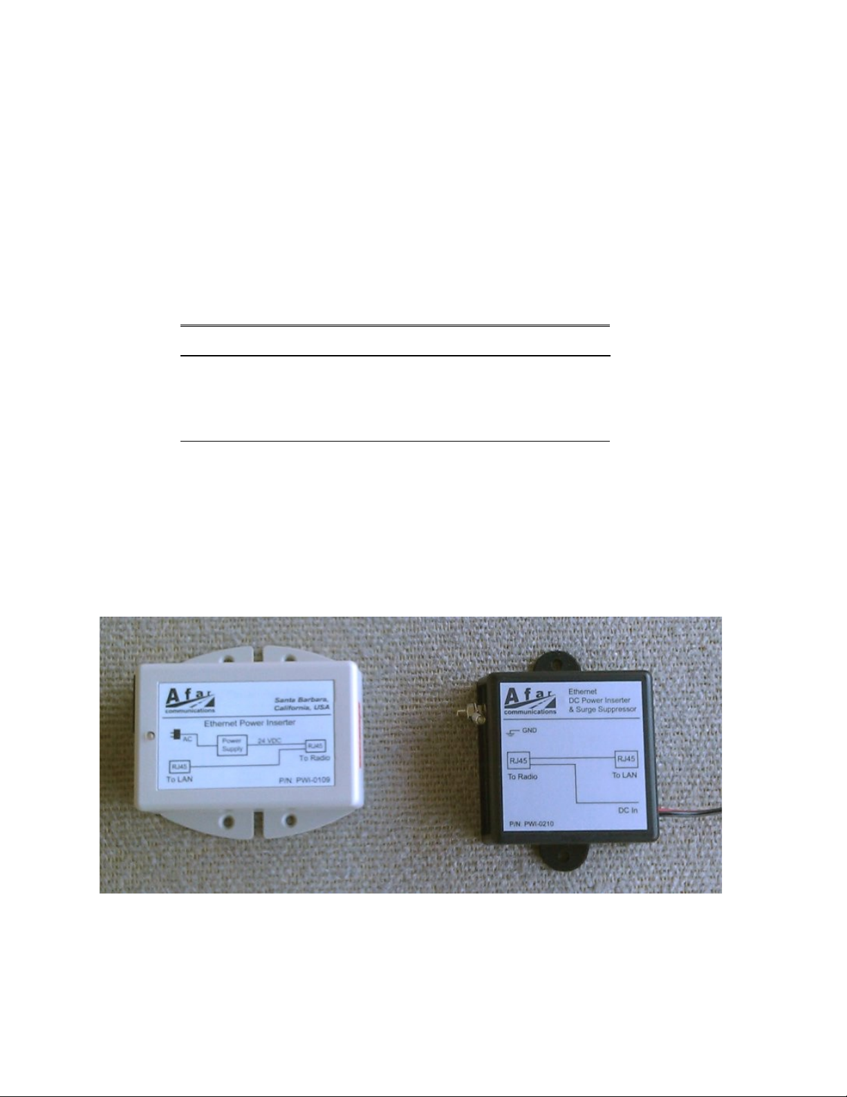
Figure .2 – AC (left) and DC (right) Power Inserter Units
1-4

pulsAR radio Operator's Manual
Alternatively the radio may also be powered over the spare cat5 line pairs (pins 4-5 and 7-8). On
these lines the radio accepts a DC voltage over a very wide range (10 VDC to 58 VDC), allowing it to
easily be powered by a 12 V battery. This method is not in compliance with the IEEE 802.3af mode
B, which restricts the voltage range to 48 VDC.
Afar provides two Power Inserter devices (figure 1.2) that use this second method. One is for
operation from an AC source (110-240 VAC), and the other for operation from a DC source (10 to 58
VDC).
The AC Power Inserter Unit includes a power supply for connection to an AC outlet (110-240 VAC).
The DC Power Inserter Unit comes with a 10 ft pigtail for connection to your DC supply voltage.
Both inserters have two RJ45 connectors and an LED. The two RJ-45 connectors are labeled “To
LAN” and “To Radio”.
Table .5 – Power Inserter Units
Connector/LED Type Function
To LAN RJ-45 10/100 Base-T to be connected to the Local Area Network. You
can connect this directly to the LAN port of a computer or to an
Ethernet hub. The radio auto-detects and provides the cross-over
function when required. See table 1.5 for pin assignments.
To Radio RJ-45 Carries the DC power and Ethernet signals to the radio. See table
1. for pin assignments.
LED
(AC Power Inserter)
Amber/
Green
Amber: Indicates that the power inserter unit has power from the
wall supply but no power is being drawn by the radio.
Green: Indicates that the radio is drawing power.
LED
(DC Power Inserter)
Green Indicates that there is DC power in the pigtail input
WARNING
The Power Inserter connectors labeled “To radio” includes DC voltage in two of the pins. It must
not be connected to a LAN as this voltage may damage some LAN cards.
1-5

pulsAR radio Operator's Manual
Table .6 – “To LAN” Ethernet Connector Pin Assignments
Pin Signal Name Abbr. Direction
1 Ethernet Tx Tx (+) Radio to Ethernet(1)
2 Ethernet Tx Tx (-) Radio to Ethernet(1)
3 Ethernet Rx Rx (+) Ethernet to Radio(1)
4 (not connected)
5 (not connected)
Ethernet Rx Rx (-) Ethernet to radio(1)
7 (not connected)
8 (not connected)
(1) With auto-negotiation enabled the radio also provides an automatic cross-over function.
Table .7 – “To radio” Ethernet Connector Pin Assignments
Pin Signal Name Abbr. Direction
1 Ethernet Tx Tx (+) Radio to Ethernet
2 Ethernet Tx Tx (-) Radio to Ethernet
3 Ethernet Rx Rx (+) Ethernet to Radio
4 VDC DCV (+) Power Inserter to Radio
5 VDC DCV(+) Power Inserter to Radio
Ethernet Rx Rx (-) Ethernet to Radio
7 ground GND(-) Power Inserter to Radio
8 ground GND(-) Power Inserter to Radio
.5 Outdoor Interconnect Cable
The interconnect cable between the Power Inserter Unit and the radio carries the following signals
1. DC voltage to supply power to the pulsAR radio.
2. 10/100 Base-T Ethernet data.
Both these signals are carried in a single CAT 5 cable. The system is designed to allow cable lengths
in excess of the 100 meters (300 feet) of the IEEE Ethernet specification. Figure 1.3 shows the
interconnect diagram for this cable and connector types. Table 1.8 lists a few part numbers and
sources of appropriate CAT 5 cable for this application. Afar Communications Inc. carries several
pre-made cables of different lengths. See Appendix D for connector diagrams, part numbers, and
assembly instructions.
1-

pulsAR radio Operator's Manual
Figure .3 - CAT 5 Outdoor Interconnect cable diagram
Table .8 – Indoor/Outdoor Unit CAT 5 cable
Part number Manufacturer Description
7919A Belden Shielded outdoor rated cable
18-241-31(gray)
18-241-11 (beige)
Superior Essex Unshielded outdoor rated cable
5EXH04P24-BK-R-
CMS-PV
CommScope Unshielded outdoor rated cable
2137113 (ivory)
2137114 (gray)
General Cable Unshielded outdoor rated cable
BC1002 Belden Unshielded outdoor rated cable
1-7
RADIO_ETH_TX+
RADIO_ETH_TX-
RADIO_ETH_RX+
VDC
VDC
RADIO_ETH_RX-
GND
GND
1
7
2
3
5
4
8
1
2
3
4
5
7
8
RJ 45
male
Radio “D” Port
(Lumberg Connector)

pulsAR radio Operator's Manual
2 NETWORK TOPOLOGIES AND
APPLICATIONS
2. Network Topologies
You can deploy the pulsAR radios in a variety of topologies from a simple point-to-point link to
complex networks with multiple hops, redundant nodes, and mobile nodes. In all applications the
radios will act as bridges connecting the LANs from all sites together. From any LAN you will be
able to access stations at all other sites, even when they are several hops away. The radios will
perform all the packet switching, sending packets in the appropriate direction so that they reach their
destination with the minimum number of hops.
The following table lists the various topologies that are possible and gives you a brief description for
each. Subsequent sections explain these topologies in more detail.
Topology Description
Point-to-point Single link between two points. For fixed sites use directional antennas to
reach distances exceeding 80 km (50 miles).
Point-to-Multipoint Central site with a single hub radio with links with up to 32 remote sites.
The hub radio autonomously allocates bandwidth “on-demand” to each
remote radio. You can co-locate multiple hub radios to increase total
capacity or maximum number of remotes.
Point-to-Multipoint
with Redundant Hubs
Two hub radios at the central site operating on different channels. The two
hubs double the total throughput available but if one hub fails the other hub
takes over and services all the remotes.
Tree topology One root node with direct links to up to 32 remotes (like in point-to-
multipoint). Any of the remotes can be promoted to a branch. A branch
node operates as an access point for up to 32 additional remote nodes
downstream (which can themselves be promoted to branch nodes). Radios
come with two antenna ports, you can deploy a branch node with one
directional antenna pointing at the parent, and a second omni antenna to
serve as an access point.
Linear Network Used for long networks with multiple stations along a railway, pipeline or
roadside. Each node has at most two neighbors. Use the radio dual antenna
port to deploy each radio with two directional antennas pointing at each
neighbor.
Loop topology Extension of the Linear Network with an additional link between the last
node back to the first. Then, if any one link goes down the radios still keep
connectivity between all nodes.
Roaming Used with mobile nodes that move around an area with multiple fixed
access points. The mobile radios change the access point automatically to
keep you connected to the fixed network. Can also be used to provide a
redundant path from a leaf node in the Tree network.
2-1

pulsAR radio Operator's Manual
2.1.1 Point to point
In a point-to-point topology, when the two sites are fixed we recommend using directional antennas at
both ends, pointing at each other. This increases the signal strength in the desired direction and
shields the radios against unwanted interference from other sources. When you use directional
antennas make sure you install both antennas with the same polarization (vertical or horizontal). Most
often interfering sources are vertically polarized so you may want to install your link with horizontal
polarization to get some additional isolation against those interference sources.
The point-to-point topology operates like a point-to-multipoint network where the hub has a single
remote. You still need to configure one of the two radios to be the hub but configure it with the max
number of children set to one. This optimizes the radio performance for point-to-point operation. See
the node command in section 4.
2.1.2 Point to Multipoint
In a Point to Multipoint topology one radio is designated as the hub and all other radios are
designated as remotes. You can have up to 32 remote nodes. You typically deploy the hub radio
with an omni-directional or sectorial antenna so that it can cover all the remotes. If the remote sites
are fixed deploy them with directional antennas pointing at the hub. If the remotes are mobile use
omni-directional antennas everywhere.
Remote radios connect to the network automatically without need to change the configuration of the
hub radio. All you need is to point an antenna at the hub and ensure that the following parameters are
configured correctly:
1. The RF receive channel of the remote must match the transmit channel of the hub (see rf- -
setup).
2. The network-id parameter of the remote must match the network-id of the hub (see node
command).
3. The max-children parameter at the hub must be large enough to give access to all the planned
remotes (see node command).
There are situations when you may want to deploy multiple hub radios at the central site. These
situations include:
You need to increase total throughput of the central site.
The number of remotes increases beyond 32.
Provide hub redundancy.
In these situations configure each co-located hub to operate in non-overlapping channels. Refer to
section 2.4 for additional guidelines on how to synchronize the transmissions from the multiple hubs.
For hub redundancy you need to configure the remote nodes to roam between the two channels used
by the two hubs. You can split the remotes into two groups with one hub servicing each group. If one
hub fails or there is strong interference in that channel, then the remotes will reattach to the other hub
keeping the connection to the central site intact. Refer to section 2.2 for the roaming options.
2-2

pulsAR radio Operator's Manual
2.1.3 Tree topology
In a tree topology you have three node types: one root node and multiple branch and leaf nodes (use
the node command to configure the node type).
The root node performs a similar function to the hub in a point-to-multipoint topology and can have
up to 32 direct links to remote sites. The radios at the remote sites can be configured as either leaf or
branch nodes. A leaf node is similar to the remote in a point-multipoint topology. But a branch
node, besides having a link to a parent (root or another branch), also operates as an access point for
up to 32 additional remote nodes (children). Each of those nodes can again be configured as either a
leaf or a branch. There is no limit to the number of levels in the tree.
A branch node has two independent RF configurations, one for the link with the parent, the other for
the links with its children. Typically you set the link with the parent to use antenna A, and the link
with the children to use antenna B. This allows you to deploy a directional antenna pointing at the
parent node, while using an omni-directional or sectorial antenna for the links with the multiple
children. This is not mandatory, you can configure a branch radio to use a single antenna.
With a large network with many branch nodes you must pay special attention to the channel
assignments. One simple approach is to allocate non-overlapping channels to each “cell” (a cell
consists of a parent with all of its direct children). At the parent set both the transmit and receive
channel to the channel that you assigned to that cell. At the children set them to receive from the
2-3
Figure 2. : Tree Topology
Root
Branch Leaf
Root
Branch
Leaf

pulsAR radio Operator's Manual
parent in that same channel (see commands rf- -setup and rf-2-setup). Once enough distance
separates cells you can start re-using overlapping channels.
The tree topology has the following features:
There is no limit to the number of levels on the tree.
Automatic association of new remote radios: just configure a new remote to receive on the
transmit channel of the desired parent, and it will automatically associate to the network (use the
“network-id” of the node command to prevent unauthorized radios from attaching).
Self-learning bridging algorithm: the radios automatically learn the addresses of your equipment
attached on any of the LANs and route the packets using the minimal number of hops to reach
their destination.
Self-healing network: If a parent node goes down a branch continues to operate and pass data
between its children. Once the parent recovers the branch automatically reattaches to the rest of
the network.
Dual antenna root mode: You also have the option of running the root with two antennas. This may
be useful if your remotes are grouped geographically such that you can use two directional or
sectorial antennas to cover each group. To run in this mode set the node type to root-2 and use rf- -
setup and rf-2-setup to configure the RF parameters for each antenna.
Tree Network throughput: A branch radio allocates half of the time to communicate with its parent
and the other half with its children. A root radio does not have a parent, so it divides its children into
two groups communicating with one group during the first half cycle, and with the second group
during the second half. Each of these two groups gets half of the total network capacity. Therefore in
the tree topology the maximum throughput available at one specific node in the tree is half of the total
network capacity. This is irrespective of the level in the tree, i.e., there is no further drop in
throughput as you go down the various levels.
2.1.4 Linear Network
A Linear Network topology is ideal for providing communications in systems that naturally require
stations deployed along a line. Some of the applications are:
Railway wayside communications
Pipeline communications
Highway roadside communications
Long links that requires multiple repeaters between the end points
2-4

pulsAR radio Operator's Manual
You can easily implement a Linear Network as a subset of the Tree topology: configure the leftmost
radio as a root and all the radios in the network as a branch. Install each radio with two directional
antennas pointing at their two neighbors.
2.1.5 Loop Topology
If the geographic location of the various nodes is appropriate you can deploy a “loop” network. This
is similar to the Linear Network above with the addition of a link between the last node and the first.
In this deployment you configure every node as a branch. The radios automatically select one of the
nodes to become the root and the loop operates as a linear network with no traffic in the link to the
“left” of the self-selected root, which avoids a continuous loop. If any one of the individual links
goes down due to interference or obstructions, the loop reconfigures itself such that connectivity is
still kept between every node.
2.2 Roaming
2.2.1 Operation
With the roaming option, a remote, leaf, or even a branch node, can be configured with multiple
different receive channels (see command roam). With this capability you can deploy multiple
access points in a region where a group of mobile radios will move around. Mobile radios attach to
the network through any of the access points and automatically switch to a new one whenever the
need arises.
This capability is ideal for communications between a control center and vehicles, where the vehicles
must move beyond the range of a single hub radio.
All the access points are typically connected, through a backbone network, back to a central site.
This backbone network can be wired or wireless. You can use the tree topology and have each
branch and root serve both as access points and backbone nodes to bring the traffic back to the central
site (see figure).
The overall system supports the following features:
1. Mobile nodes automatically attach to the strongest access point.
2. As a mobile unit moves and the link to its parent fades, the mobile radio changes autonomously
to attach to a stronger parent.
2-5
Figure 2.2 - Linear Network Topology
This manual suits for next models
4
Table of contents
Popular Network Router manuals by other brands

GREAT ARBOR
GREAT ARBOR GAC-300 user manual

Advantech
Advantech UR5i v2 Libratum user manual

ZyXEL Communications
ZyXEL Communications Prestige 941 user guide

Airlink101
Airlink101 AR325W Configuration guide

Digi
Digi TransPort WR41 installation guide

Linksys
Linksys BEFSR41 - EtherFast Cable/DSL Router user guide


Comtrol
Comtrol ROCKETLINX ES7110 Quick installation guide

Atlantis
Atlantis NetMaster G16 Multilanguage manual

OptConnect
OptConnect neo 2 quick start guide

Ruckus Wireless
Ruckus Wireless ZoneFlex 7731 Getting started guide

Epson
Epson OT-WLO5 user manual

Pakedge Device & Software
Pakedge Device & Software RB-KIT installation manual