AFRI-CAT 420 User manual
New Adventure Operating Manual – 5/1/2011
1
Welcome to the New Adventure!
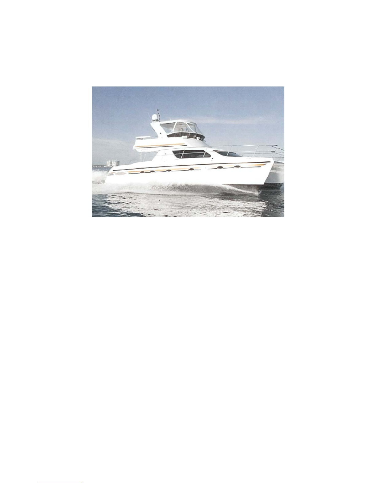
2005 42’ Africat Power Catamaran
THE AFRICAT 420
Thank you for chartering the “New Adventure”. Power catamarans are not common on the west coast,
but they are very popular in the Caribbean and in Florida where we bought the boat in February, 2008.
They have both disadvantages and advantages relative to a similar sized monohull boat. On the positive
side, our experience is that they are very stable and tend to ride better than a monohull in rough waters.
With a width of 22’ the New Adventure is much roomier than a monohull of the same overall length. It
has three staterooms each with its own private head, and the master stateroom suite has its own separate
shower stall. In addition it can get up to 40% better fuel economy and cruises at a comfortable 16 to 18
knots. With its shallow draft of just over 3’, it can access shallow areas not available to most monohulls.
On the negative side the width of the boat is larger than most marina slips, so getting a moorage is more
difficult.
You’ll find that if you familiarize yourself with this handy manual you’ll be able to start enjoying your
cruising vacation. If you have any feedback or suggestions on the completeness or clarity of the manual,
please leave a note in the binder.
This document is not intended to be a comprehensive user’s guide to this vessel or to yachting in
general. Please be sure that the AYC check out or skipper training program has provided you with a
good understanding of the various systems and their operation before departure and that you feel
comfortable in your ability to safely handle the boat at all times.

New Adventure Operating Manual – 5/1/2011
2
We are maintaining the high quality of this boat not only for ourselves but also for all of our
guests. Please help us by assuring the following:
No smoking onboard
No pets
Remove shoes when on the boat
No crab cooking in the cabin
This manual is provided to AYC for distribution. Please refer any questions or concerns to Anacortes
Yacht Charters.
New Adventure Layout

New Adventure Operating Manual – 5/1/2011
3
Table of Contents
Welcome and Overview.......................................................................................page 1-2
Table of Contents…………………………………………………………….....page 3
Safety…………………………………………………………………………...page 4-5
Basics (breakers, switches, and controls)...…………………………………….page 5-8
Engines………………………………………………………………………….page 8-9
Instruments and alarms………………………………………………………….page 9-11
Household (toilets, water pressure, stove, etc.)…………………………………page 11-15
Electrical System………………………………………………………………..page 15-17
Electronics………………………………………………………………………page 17-18
Tanks (water, diesel fuel, waste).……………………………………………….page 18-19
Anchoring, Dinghy, and Outboard……...………………………………………page 19-22
Other Issues……………………………………………………………………..page 22-23

New Adventure Operating Manual – 5/1/2011
4
Safety
Safety Equipment
The following safety equipment is located on board the New Adventure. Everyone on board should be
familiarized with the safety equipment and with proper emergency procedures.
Life vests/life ring
At least four USCG approved adult life vests are stored in the hatch under the forward seat of the table
in the cockpit area or in the rear cabinets. Two are stored in the forward hatch on the dinghy, and two
more are located in the starboard hatch on the fly bridge. Two children’s vests are also provided, but as
they come in many different sizes you may wish to supply your own.
A type-III throw able life ring hangs on the wall at the front of the cockpit area.
There is a Lifesling overboard rescue system located in the starboard hatch on the fly bridge.
Boarding Ladder
A boarding ladder that fits in a fixture on the back of the starboard aft step platform is located on the hot
water tank in the starboard engine compartment.
Flare Kit
A USCG approved flare kit is located in the starboard locker in the fly bridge, along with spare flares,
signaling devices, and other required safety communication items.
First Aid kit
The First Aid kit is located in the master (starboard) stateroom bathroom, in the cupboard opposite
and aft of the sink.
Fire Extinguishers
Master stateroom: at the stairs down from the salon (on the starboard side)
Guest staterooms: at the stairs down from the salon (on the port side).
Main salon: at the entry door on the port side.
Cockpit area: in the center left cabinet in the rear set of cabinets.
Fly bridge: inside the starboard hatch below the control station
Communications
The VHF radios at the nav station in the salon and on the fly bridge default to channel 16 which is the
international distress, safety and calling frequency. Please refer to the VHF users guide for more
information.

New Adventure Operating Manual – 5/1/2011
5
You may also wish to bring your own cell phone.
Electrical breakers
The batteries for each of the engines and the battery bank for the house power system are protected by
large red circular breakers. The engine breakers are located in the bed area of the port and starboard aft
bedrooms; the house power breaker is located at the salon nav station next to the breaker for the
windlass, below and to the right of the AM/FM radio. You should never need to touch these, and they
should always be left on, even when leaving the boat (to provide power for battery charging, some
pumps, etc).
Except in an emergency, these should never be touched while the engines are running since suddenly
cutting power may damage alternators and other systems on board.
However, in the event of an emergency such as an electrical fire when you may decide you need to cut
all 12v power to the boat, you can do so by throwing these three switches.
Through-hulls
Assortments of wooden through–hull plugs are located in both engine compartments near the sea-
strainers.
BOAT BASICS
The switches on the DC and AC panels are covered in this chapter. For information on the electrical
system in general, batteries, inverter, charging, etc, please refer to electrical system section.
12V DC panel
The 12V DC panel controls all the 12 volt circuits on the boat except those to start the main engines and
generator, i.e. all the things that run off the main house batteries. It is located on the left of the salon nav
station.
The panel is divided into five columns of breakers. From left to right these include:
1. Breakers for lights on the boat and for the satellite TV antenna

New Adventure Operating Manual – 5/1/2011
6
2. Breakers for water, sump, and toilet systems, and for the engine blowers
3. Breakers for top fridge, freezer, 12V DC outlet on fly bridge, fly-by-wire (engine controls), and
tank management system
4. Breakers for navigation electronics, the radio (music system) at the nav station, the auxiliary fuel
tank pumps, the windlass, and the electronic propane safety system
5. Bilge pump breakers with alarm and lights when pumping
Bilge pumps
ALWAYS, always leave the bilge pump breakers in “ON” position.
Household stuff
Many other breakers on the 12V DC panel can be left on:
First column -
Cabin lights and salon lights as they are controlled by switches portside of the sliding door or in
the cabins
Nav lights as they are controlled by a rotary switch on the panel to the left of the salon nav station
C120 terminal (this switch has settings for different operating conditions – anchoring, underway, etc.)
Second column -
The water system, grey water, and all toilet related breakers should remain on
Third column -
The upper fridge (under the seat on the fly bridge) if it is used
The freezer located under the salon seat to starboard if it is used
DC outlet and tank management
Fourth column -
The music system powering the radio at the salon nav station
The gas control that manages the propane supply to the stove
Note: if you hear a pump running continuously, then please try to track it down (turn off breakers until
the noise stops) and figure out why it’s running. This will prevent the pump from running dry and
burning up.
Instruments and electronics
The fourth column of breakers includes those for the various electronics needed when running the boat.
These are best left off when not traveling:
VHF radio
Autopilot
Radar plotter
Other switches
The following breakers generally act as on/off switches and therefore should only be turned on when
you actually need them:
Courtesy lights

New Adventure Operating Manual – 5/1/2011
7
Aft deck lights
Bridge lights
Engine room lights
Sat TV (this controls the satellite TV antenna that is not available during charter)
Auxiliary fuel tank transfer pumps (these are only activated when transferring fuel from the
auxiliary tanks to the main fuel tanks)
AC Panel
The 110V AC panel is to the left of the 12V DC panel, and has two columns of breakers and two gauges
for voltage and amperage. It controls the various 110V systems on the boat, and indicates with lights at
the top left of the panel where the 110V power is coming from – generator, shore power, or inverter.
The left column of breakers has:
Heat Pump/Air Conditioner port and starboard. These will only operate when the generator is
running or when connected to 50 amp shore power.
Hot water heater. This breaker is also only operational when the generator is on or when
connected to shore power.
The Sal Outlets breaker controls the outlets in the salon at the microwave and the toaster over. To
protect the inverter these outlets are only active when the generator is on or when connected to shore
power.
Note: If you are on 30 amp shore power, you can only run one Heat Pump/Air Conditioner at a time.
The right column of breakers has:
Outlets at all locations on the boat except for the microwave and toaster oven outlets described
above and the Nav Outlet explained below.
Salon refrigerator.
Nav Outlets (these are the outlets above and forward of the salon nav station).
Salon ice maker.
Surround sound.
Note: Some 110V outlets have switches on them to activate the outlets. These must be on in addition to
the outlets breaker for the outlet to be active.
The inverter will power both the ice maker and salon refrigerator, so both will remain on under all three
110V power conditions if the breakers are on.

New Adventure Operating Manual – 5/1/2011
8
Power selection
The 110V power source is determined automatically by the Xantrex inverter controller. When shore
power is connected the shore power light will turn on; when the generator is started the generator light
will turn on; when shore power and the generator are not available, the inverter light will turn on (if the
inverter is turned on at the Xantrex panel). A house bank of six batteries is located under the salon seat
and supplies both the 12V power for the boat (except for that required by the engines) and the 12V
power for the inverter. The batteries’ condition is shown on the Xantrex panel located to the left of the
salon C120 Raymarine display. If the voltage reduces to 10.5V when operating under inverter power,
the inverter will turn off until the house batteries are re-charged. Under normal conditions you will not
have to touch anything on this Xantrex panel as most operation is automatic.
Generator Controls
The panel for the generator is located below the 12V DC panel at the nav station. It includes
Run switch for turning on or turning off the generator (on is up)
Start switch for starting the generator (down is preheat and up is start)
Gauges showing voltage, temperature, and oil pressure
Generator hour meter
Note: see the manual for more info on the generator
Engines
Please refer to the Anacortes Yacht Charter boat manual for standard AYC departure checklists and
daily procedures. This section only provides a quick reference on the mechanics of starting and
stopping the engines, maneuvering and cruising.
Pre-start
1. Standard Anacortes Yacht Charter pre-start checks
2. Bilge pumps should be on
3. Throttle levers (black) should be in NEUTRAL in salon, at aft station, and at fly bridge
4. Fly-by-wire breaker on the 12V DC panel should be turned on. A beeping noise will be heard
from the engine controls at the nav station and on the fly bridge accompanied by yellow flashing lights.
Press down twice on the control at the left side of the lights, the beeping will stop, and the two yellow
lights will remain on without flashing. This indicates that these engine controls are active.
5. VHF radio, Autopilot, and Radar plotter breakers should be turned on
Starting the engines
1. The engines can only be started or turned off from the salon nav station.
2. Turn the key for the port engine to the start position until the engine fires, usually no longer than 1
or maybe 2 seconds (watch the tachometer, as soon as you see a positive value the engine has fired).
The engine alarm buzzers may sound at this point; this is normal and confirms the alarm is functioning
properly. Don’t crank for more than 10 seconds. If engine doesn’t start, wait about 1 minute and try

New Adventure Operating Manual – 5/1/2011
9
again. If it fails on the second try, something needs fixing before continuing. The engine alarms should
shut off shortly after the engine starts.
3. Repeat for the other engine
4. Go to the fly bridge and turn on the engine keys so that the engine gauges are turned on also at the
fly bridge
5. Engines can be turned off at either the salon nav station or the flybridge. Leave keys in the "on"
position and push the red stop button. After the engines have stopped, turn keys to "off".
Operating the boat
1. To activate the engine controls at any one of the three control stations (salon, fly bridge, and rear
port side of the cockpit area), press down on the control at the left side of the lights. A beeping will be
heard and the two yellow lights will flash. Press once more so that the beeping will stop and the two
yellow lights remain on without flashing. This indicates that these engine controls are now active. Note
that you can only get control at a new station if the levers for all stations are in neutral.
2. The aft controls are often useful when docking. Please make sure the cover for the aft controls is
put in a safe place when the controls are in use and replaced over the controls when they are not in use.
The controls can be damaged if they get wet.
3. Note that rudder steering control is only available on the flybridge.
Spare engine oil, transmission fluid, coolant, and steering fluid are located in the starboard hatch under
the rear-facing seat in the cockpit area.
Shifting
Shift gears only when the engines are idling. In most cases maneuvering when docking or anchoring
can be accomplished with the controls only moved from neutral to the first stop of the forward or reverse
gears. Please note that the throttles are very sensitive!
Cruising
Once you are headed out to open water and want to increase speed, bring the engines up to the desired
cruising RPM. Move both throttles at the same time to keep the Rpm in the same range.
Cruising RPM is anywhere from 2700 to 3200 RPM. This gives about 15 to 20 knots depending on
weight and other conditions of the boat. Please do not run the engines above 3200 RPM. If you
operate the engines at 1800 to 2000 RPM, you will run at approximately 8 knots and get
significantly better fuel economy. If you run above 3000 RPM you will significantly reduce fuel
economy.
Run the engines within about 10 RPM of each other (“synchronized”).
New Adventure Operating Manual – 5/1/2011
10
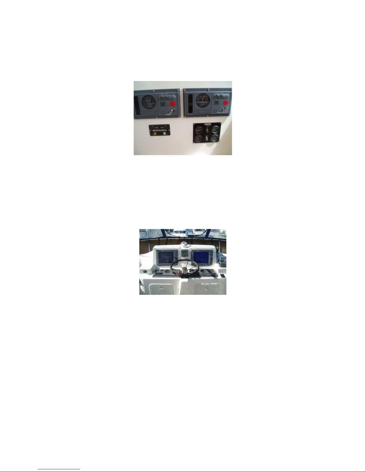
Instruments and alarms
Main engines instrument panels
Salon nav station engine instrument panels for each of the two main engines have:
RPM gauges.
Hour meter
Oil pressure, alternator, and temperature alarm lights
Starter keys
Off buttons
The fly bridge helm instrument panel is similar but also includes gauges indicating engine temperature
and oil pressure. It cannot be used to start the engines.
Note: The engine oil pressure gauge on the fly bridge for the port engine sometimes is malfunctioning
and mistakenly indicates a lower and sometimes erratic oil pressure than the starboard engine.
Alarm panels
The salon nav station and the fly bridge helm have optical alarm panels for each engine. The panels will
light up for the following:
Engine temp-triggered if engine overheats
Oil pressure-triggered if oil pressure is too low
Alternator failure-triggered if fan belts break or alternator fails

New Adventure Operating Manual – 5/1/2011
11
Additionally, there are red warning lights for the following:
Bilge pumps. These lights may come on from time to time when the pumps operate. If they do,
check the bilge for excessive water indicating that the boat may be taking on water.
An audible alarm for the bilge pumps can be turned on at the 12V DC panel with the switch below
the bilge pump breakers.
If the engine controls fail the red lights on the control stations labeled “alarm” will light and an
alarm will sound.
A few minutes after the VHF radio is first turned on it often sounds an alarm for a few seconds. This
indicates that the speaker is working and should not be a concern.
If the bilge pump alarm is on and sounds, this simply indicates that one of the bilge pumps is operating.
This is normal. If the pump stays on for extended periods of time check to see that everything is ok as
described above.
If the engine alarm sounds or the panel indicates that there is an engine problem, immediately bring the
engines down to idle and then turn them off. Troubleshoot to try to find the source of the problem.
Continuing to run the engines when an alarm is on may damage the engines.
The Household
Heads (toilets)
To prevent truly unpleasant troubles with the heads, follow a few simple rules:
Don’t put ANYTHING into the toilets other than the marine toilet paper supplied on the boat and
what you’ve already digested. No cotton balls, bubble gum wrappers, floss, paper towels, etc.
Make sure every guest follows the first rule.
Only use the toilet cleaners provided.
Remember that the cost to repair a plugged or damaged head is the liability of you, the charterer.
All heads are fresh-water vacuum-flushing toilets. They are very simple to operate and use very little
water (helps conserve fresh water supply and shortens pump-out time).
Both the fresh water pump breaker and all toilet-related breakers must be on.
To flush, simply press the button at the left rear side of the toilet.
Note: you will hear the vacuum pump come on for about 10 seconds, and the fresh water pumps may
also come on to re-pressurize the water supply. These should turn off within a short period of time.
Note: there are two black water tanks, one port and one starboard, with pump-out connections located at
the top and rear of each hull.
Note: the discharges from the holding tanks are below water line on both the port and starboard hulls

New Adventure Operating Manual – 5/1/2011
12
just forward of the aft beds, with sea cocks located under the hull floors in the aft bedroom areas. This
is for discharge at sea, but the sea cocks must remain closed when in inshore waters and the tanks must
be pumped out when full. If needed, a fitting that mates the waste discharge ports on the hulls at the rear
of the boat to some pump-out hoses is located in the hatch under the swim steps on the starboard side.
Tank Sentry
The level in the black water holding tanks is shown for both hulls by a tank sentry panel. The starboard
panel is located on the bathroom wall near the toilet; the port panel is located in the forward bathroom
on the side of the medicine cabinet above the sink. These panels have a lower on/off switch, an upper
alarm switch, and a middle switch to turn on the macerators for discharging black water into the sea.
The macerators are wired so that they will not operate until the sea cocks are open. The top switch turns
on an audible alarm that activates when the tank is full, but we normally have this alarm turned off since
the panel lights indicating tank status are very visible.
Note: Indicator lights are not always accurate. In particular the port side tank sentry lights are erratic,
and since this is the side with two toilets the holding tank often fills faster than that on the starboard
side. If the toilets will not flush but are not obviously plugged, it is usually because the tank is full. If in
doubt - pump it out!!
Hot & Cold Water System
Overview
Two fresh water tanks on the boat hold up to 200 gallons of fresh water. These tanks are connected
together so there is no necessity for switching from one to the other. Electric pumps draw water from
the tanks into the water system, providing water pressure and bringing water to the various fresh water
outlets throughout the boat and on deck.
The pumps run on DC power, so as long as there is water in the tanks, the pumps are turned on at the
12V DC panel, and the house batteries are not dead, there should be water pressure.
As long as the water system is on, and there has recently been power to the hot water heater, there
should also be hot water available. Running the main engines also heats the hot water.
Water pressure
On the 12V DC panel, keep the fresh water pump breaker ON whenever you are on the boat. This will
keep the water pressure on. If this switch is on but no water is coming from the faucets, you are out of
water.
Heat Pump and Air Conditioning
There are two Technicold heat pumps on the boat, one in each hull, capable of operating either as
heaters or as air conditioners. The units are located in the rear of the engine compartments, and the
controls are located on the walls near the port and starboard aft beds. If the breakers are on and the boat

New Adventure Operating Manual – 5/1/2011
13
is either under generator or shore power, the units can be turned on, the mode of operation selected (heat
or cold), and the desired temperature set at these controls. See the Technicold operating manual for
further details. When operating, the heat exchange water pumps will exhaust water from outlets near the
water line and on the outside rear of each hull. Please check to make sure that water is being
expelled by the heat exchange pumps when first turning them on as occasionally air will get into
the pumps or they can get plugged by seaweed and they will not operate. When this happens the
unit will either stop and give a failure code on the control panel or it will make a terrible noise
depending on its operating mode. In either case turn the unit off immediately as continuing to run it
will risk damage to the unit. To fix this problem either clean the filters if they are clogged or for the
starboard unit the hose from the pump to the compressor heat exchanger must be loosened and lowered
below sea level to remove all air from the pump until the pump is clearly pumping water, then
reconnected.
Hot Water
Water in the hot water tank is only heated if the boat is on shore power or the generator is on, or the
main engines are running. You need only leave the “Water Heater” switch on (located on the 110v AC
panel) and the system will operate automatically.
Stove and Oven
Please refer to the instruction manual for operating the stove.
1. Make sure the valve at the LP tank located in the forward starboard deck hatch is on.
2. Turn on the gas circuit breaker on the 12v DC panel.
3. On the LPG panel to the right of the stove, push the left button until the green light turns on. This
opens a second valve in the gas line near the tank itself if there are no leaks or alarms in the salon. Now
you should have gas pressure to the stove.
4. To light a burner, turn the control knob counterclockwise a quarter turn and push it in. The
electronic lighter should spark and light the burner. After a few seconds release the knob and let it out.
The burner incorporates a heat sensitive auto shut-off mechanism that has to heat up or it will turn off
the flow of gas in the burner. Adjust the flame by turning the knob.
5. The same procedure is used to light the oven.
6. After using the stove, push the left green button on the LPG panel to turn off the propane and
avoid any inadvertent gas leakage.
7. There is a spare propane tank located near the main propane tank in the forward starboard deck
hatch.
8. The electronic lighting system is powered by an AA battery located under the stove on the right
hand side.

New Adventure Operating Manual – 5/1/2011
14
Microwave, Toaster Oven, and Coffee Maker
A separate microwave, toaster over, and coffee maker are located in the salon. The coffee maker will
operate when the inverter is on, but the breaker will trip if there is any other significant loads on any of
the outlets connected to the Outlets breaker. The microwave and toaster oven are located near outlets
connected to the Sal Outlets breaker, and these outlets are only active when the generator is on or when
on shore power. Do not try to use either both the microwave and toaster oven at the same time as it
will trip the Sal Outlets breaker.
Barbeque
There is a barbeque located in the aft cabinets that mounts into the port side rod holder at the rear of the
boat. A propane tank and hose/controller for the barbeque is located in the cabinet below the port side
rod holder.
Refrigerators and Freezers
There are two refrigerators, a freezer, and an icemaker/refrigerator on the boat. The main refrigerator
and the ice maker are located in the salon and both operate on 110V power. A small 12V refrigerator is
located under the forward port seat on the fly bridge, and a large 12V freezer is located under the
starboard seat in the salon.
To counteract the formation of water condensation on the top of the freezer, we have placed an
insulating panel under the seat cushion and over the hatch covers to the freezer. We do not necessarily
like this solution but are still thinking about how to improve upon it. Suggestions are welcome!
Showers
To use:
1. Water pressure is required (fresh water pump breaker on 12V DC panel)
2. Make sure the grey water breaker is on. There are small water pumps under the floor in both hulls
to pump the grey water overboard.
3. For the portside showers in each of the stateroom bathrooms, please protect the toilet paper, toilet
flush control, and other items from getting wet when using the showers.
4. Turn on the tap and then push the button on the shower head to shower.
5. The master suite shower operates like a normal shower in your home.

New Adventure Operating Manual – 5/1/2011
15
Please carefully dry off the bathrooms after showering to prevent mould and odors.
The key to conserving water is to take what are called ‘boat showers’: As soon as the water is at a
comfortable temp, wet down quickly, then turn off the water flow. Lather up. Turn water flow back on
to rinse off, and then you’re done.
It’s best to shower when you have been on shore power (or generator or main engines) for awhile, so
that the water heater will have had time to heat enough water for you. Also, if you’ve just washed
dishes or otherwise used a lot of hot water, you may run out during your shower!
If you run out of hot water, it will take the water heater some time to heat more water, and you will need
to be either on shore power or generator power to do it.
TV & Stereo
There is a 42” plasma TV monitor mounted in the salon above the sliding glass doors. It is connected to
a Direct TV receiver that is for owner use only. However it is also connected to a home theatre system
mounted above the sliding glass doors that will play DVD’s, CD’s, and serves as an AM/FM receiver.
Both operate at 110V and are turned on at the AC panel with the “Outlets” breaker. Unfortunately one
needs to operate two remote controls to use the system for DVD’s, one for the plasma TV monitor and
one for the home theatre system. The TV control turns the monitor on and off and must be
independently set for the input to respond to the DVD player. The player, AM/FM receiver, and the
sound system are all controlled by the LG remote. Both remotes are kept in the middle drawer under the
seat at the salon nav station.
There is another radio receiver located at the nav station that is connected to the Bose speakers mounted
under the front salon windows. It also has a CD player and MP3 input. It is turned on at the DC panel
with the “Music System” breaker. Please see the operation manuals for operating instructions.
Speakers in the cockpit area
The 2 speakers in the cockpit area are wired directly to the radio located at the nav station. They act like
rear speakers in an automobile with the volume adjusted using the fader control on the radio.
Electrical System
Overview
The 12V battery system consists of 3 battery banks. There is one battery that cranks the port engine and
the generator, one battery that cranks the starboard engine, and a set of six gel batteries that supplies the
12V DC panel and also supports the inverter. The Xantrex inverter system utilizes the house battery
bank by automatically turning the inverter on when neither shore power nor generator power is available
to assure a supply of 110V AC power. The engine alternators charge both the engine and the house
batteries via a battery combiner when the engines are running.

New Adventure Operating Manual – 5/1/2011
16
Shore power
A shore power connection is available at the port stern. The 50’ power cable is located in one of the aft
hatches under the rear-facing seats. A 30A to 50A connector is kept with this cable, as well as a 15A to
30A adapter. In the Pacific Northwest very few marinas have 50A service, so it is recommended that the
boat normally be connected to 30A service at all marinas. Please note that both air conditioners
cannot be used at the same time when connected to a 30A service, as each air conditioner takes
approximately 20A when operating.
When connecting to shore power please make sure to do it in the following way:
Insert the power cable firmly into the connector on the aft stern of the boat and rotate it to lock the
connector in place. Screw the connector fitting on until tight.
Make sure the shore breaker at the shore power source is off. Do not try to connect the power
cable without first turning off the shore source breaker as you may damage the inverter in the
boat.
Insert the other end of the cable firmly into the shore power source and rotate the connector to
lock it in place.
Adjust the cable until it is in a safe and stable position and is not likely to be jarred or pulled
accidentally.
When you are satisfied with the cable and its connection, turn on the breaker at the shore power
source.
Charging the batteries
The engine batteries and the house batteries are charged by the engine alternators when under power,
and normally need no special procedures to remain charged. The Xantrex inverter system will
automatically charge the house battery bank and the engine batteries when either shore or generator
power are present. The Xantrex panel is located to the right of the 12V DC panel and to the left of the
salon C120 Raymarine display. The panel shows the voltage level of the house battery bank (battery 1),
and on the left of this panel there are two important buttons:
The top one is labeled “Invert” and when the green light is on this indicates that the inverter is
activated. This switch should be left on at all times as all 110V AC power is supplied by the inverter
when neither shore power nor generator power are available.
The one immediately below this button is labeled “Charger”, and this button turns the charger for
the batteries on when connected to either shore or generator power.
There are four small lights at the bottom of the panel indicating the status of the charging. The left
light indicates that AC power is available (either shore power or generator power is available to charge
the batteries); the next green light indicates charging; the next yellow light indicates accept and means
that the battery is nearly fully charged; the next green light labeled “Float” means that the batteries are
fully charged and the charger is simply supplying only the power that is being used.
Please do not try to alter the programming of this control as you may damage the batteries
and/or the inverter.
It is good practice to turn off all electrical loads before connecting to shore power or starting the
generator, only turning them back on again after the new power source has stabilized. To turn off the
battery charger, push the button labeled “Charger” on the Xantrex panel so that the green light is off.
Please make sure to push the button again when the new power source has stabilized so that the green

New Adventure Operating Manual – 5/1/2011
17
light shows and the charger is activated.
*Please refer to the Xantrex Inverter instruction manual for more information.
Generator
A diesel powered Phasor 8 kW generator is installed in a soundproof enclosure located aft in the port
engine room. The system provides 110V AC power to the boat when shore power is not available. This
generator must be used if shore power is not available and the 110V electrical appliances or the air
conditioning system are used. However if these appliances are not used the normal running of the
engines should keep the house battery bank fully charged and make generator operation unnecessary. If
you are away from shore power for long periods of time and do not run the engines, running the
generator for several hours each day will generally provide enough power to keep the house battery bank
fully charged even when continually operating the ice maker, the freezer, and the main refrigerator.
Starting and stopping
1. The controls for running the generator are all located below the 12V DC panel.
2. Make sure the upper “Run” switch is in the up position.
3. Hold the lower “Start” switch down to the Preheat position and hold for at least 30 seconds.
4. Move the lower switch up to the “Start” position. Release as soon as you see the voltage gauge
indicate 110V and the oil pressure gauge operate.
5. The Generator Power light will turn on at the AC panel.
6. Run genset 3 to 5 minutes before you put any load on unit.
To stop the generator
1. Make sure there is no heavy load on the generator (all appliances, air conditioners, and hot water
heater breakers are off).
2. Push the upper “Run” switch down to the off position.
Inverter
Running any power-hungry device from the inverter will drain the main house batteries quickly. The
inverter is best used only for small 110V devices, such as a cell phone charger for example, and to
power only the main refrigerator and the ice maker. The inverter is automatically energized and
connected when neither shore power or generator power are available. If the battery voltage is allowed
to drop below 10.5 volts the inverter will turn off, and consequently the ice maker and the main
refrigerator will turn off as they require 110V.
Other breakers
There are some additional breakers to those on the 110V AC and 12V DC panels in the salon. Several
are located behind the salon breaker panels and are accessed from the front port bedroom, and one for
the generator and for shore power is located in the port engine well. These occasionally are triggered by

New Adventure Operating Manual – 5/1/2011
18
accident and need to be reset in case power is lost and there appears to be nothing wrong with the
breakers on the salon panels. If the doors are opened in the front port bedroom directly behind the salon
breaker panels, several of these breakers will be seen. In case of problems that cannot be fixed using
breakers on the salon breaker panels, these should be checked to make sure they have not tripped, and
reset if they have. In the port engine well at the rear outside hull wall back of the generator there is a
110V breaker that occasionally trips when the generator is operating or when shore power electrical
current drain is exceeded and needs to be reset.
Electronics
VFH radios
There are two VHF radios, one on the fly bridge and one at the salon nav station. Both are turned on by
the VHF breaker on the 12V DC panel. Please refer to the radio owner’s manual for operating
instructions.
Radar
The radar is connected only to the port side Raymarine C120 terminal on the fly bridge, and is
controlled from that terminal.
Please refer to the Raymarine owners’ manual for operating instructions.
Depth sounders
Water depth is indicated on a digital display at the salon nav station and on the starboard C120 terminal
on the flybridge when the Raymarine electronics are turned on.
Electronic GPS Charts
A GPS receiver is connected to both C120 terminals on the fly bridge and to the C120 terminal at the
salon nav station. However detailed electronic navigation charts are only available on the starboard
C120 terminal on the fly bridge. These detailed charts cover the region from Olympia Washington to
the northern tip of Vancouver Island. Please refer to the Raymarine owners’ manual for operating
instructions. Do not remove or change the electronic chart memory cards in the C120 terminal.
Occasionally the alarm will sound and indicate that the GPS has lost its fix. This is caused by a
flaw in the Raymarine GPS unit and is easily fixed by going to the DC panel and turning off the
Autopilot breaker, then turning it back on.
Autopilot
The boat is equipped with an autopilot with controls at the fly bridge and the salon nav station. Pushing
on the “Auto” button turns on the autopilot and maintains the boat direction at that when the button was
pushed. Pushing on the + or – buttons on the fly bridge will alter course accordingly, and turning the

New Adventure Operating Manual – 5/1/2011
19
knob at the salon nav station will have a similar effect. Pushing the “Standby” button will disable the
autopilot and return to manual control with the wheel on the fly bridge. When the engine controls at the
salon nav station and the autopilot are activated, it is possible to operate the boat totally from the salon
nav station. However for safety reasons users are strongly encouraged to operate the boat only from the
fly bridge since that is the only location with a wheel.
Note: Puget Sound and the Inside Passage are notorious for floating debris and logs in the water, not to
mention other boats. Great care must be exercised and a sharp lookout kept at all times, but particularly
when running under autopilot.
Tanks
Water tanks
There are two 100-gallon water tanks on the vessel. These are located at the front of the boat, with
access via the port and starboard front hatches. There are two water filler caps located on the deck near
these hatches to fill the tanks, but only one needs to be used as both tanks are connected together. Keys
to open the caps are located in the top drawer at the nav station to the right of the radio.
Filling
The water tanks can be filled from any source of clean water. Remember that the water you put in the
tanks will be what you cook with, shower with, etc, so be sure to use a good clean source.
There are two water hoses in the front port hatch or in the rear cockpit cabinets which can be used for
filling the tanks. To fill:
1. Remove one of the filler caps.
2. Insert water hose into tank and turn on the water.
3. An empty tank will take at least 10 to 15 minutes to fill.
4. When the tank is full, don’t forget to screw the cap back on!
5. If the tank is overfilled, the overflow goes into the anchor well and empties from the drain hole in
the anchor well.
Checking fresh water level
You can check the water level at all times at the tank sentry panel to the left of the salon C120 terminal.
The tank sentry center gauge shows the water level and is clearly marked. Note that the tank sentry
breaker must be turned on at the 12V DC panel in order to activate the tank sentry.
Diesel fuel tanks
There are two fuel tanks aft, each with 220 gallon capacity. The port tank supplies fuel for both the
engine and the generator; the starboard tank supplies the starboard engine only. Filler caps for both tanks
are on the aft hulls, just forward of the black water pump out caps. You may have noticed two

New Adventure Operating Manual – 5/1/2011
20
additional, auxiliary fuel tanks forward that are listed on the tank sentry. We require the auxiliary
tanks NOT be used during chartering.
Filling
1. Open the main diesel fuel filler cap at the rear of the boat on one hull using one of the keys located
in the top drawer at the Nav station to the right of the radio.
2. Begin fueling. Keep a careful eye and ear on the process, and keep a rag or paper towel handy to
sop up overflow at the filler cap or at the breather vent. As the tank is filling, you’ll have several clues
that it is almost full:
a. The tank sentry will indicate full
b. Fuel will overflow from the vent
c. When it gets very close to full, the sound will change
3. Don’t overfill. Screw the cap back on.
4. Repeat the process for the main fuel tank at the rear of the boat in the other hull.
Checking fuel levels
You can check the fuel level in both tanks at all times at the tank sentry panel to the left of the salon
C120 terminal (where fresh water levels are shown). The tank sentry left and right gauges show the fuel
levels for the main fuel tanks and are clearly marked. Please note that the readings on the tank sentry
are approximate and should not be used to determine the actual level of the tanks. In fact the port side
level indicator is sometimes erratic and should not be relied upon. In practice the two tanks tend to track
fuel levels quite closely regardless of generator usage. Note also that the tank sentry breaker must be
turned on at the 12V DC panel in order to activate the tank sentry.
Anchoring, Dinghy, and Outboard
Anchoring with the windlass
There are 200 feet of chain connected to 50 feet of rope for anchoring using the windlass, as well as a
separate aluminum Danforth anchor located in the forward port deck hatch with 50 feet of chain and 100
feet of rope for double anchoring or anchoring manually. The windlass power breaker is located at the
salon nav station to the right of the radio and next to the house batteries red main switch.
Anchoring is two-person job as the boat operator cannot see the anchor chain or the anchor chain
and the windlass operation from the bridge. Please do not try to do it alone. Once windlass power
has been turned on at the 12V DC panel and the breaker has been reset, the windlass can be operated
from either the fly bridge or at the bow with the foot switches. Best control is from the bow as the
operator can see both the chain and the windlass operation. In addition the chain has marks every 25
feet with the code for the markings written on the underside of the anchor hatch cover, so these can only
be determined when operating the windlass using the bow foot switches.
Table of contents


