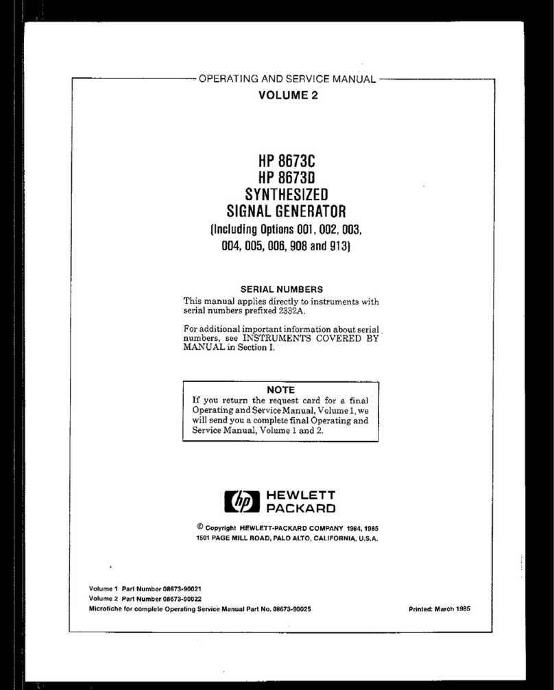
Agilent Technologies HP 83711A Use and care manual

Printed in USA March 2000
Notice
Hewlett-Packard to Agilent Technologies Transition
This documentation supports a product that previously shipped under the Hewlett-
Packard company brand name. The brand name has now been changed to Agilent
Technologies. The two products are functionally identical, only our name has changed. The
document still includes references to Hewlett-Packard products, some of which have been
transitioned to Agilent Technologies.

2Chapter1
Contacting Agilent
By internet, phone, or fax, get assistance with all your test and measurement needs.
Table 1-1 Contacting Agilent
Online assistance: www.agilent.com/find/assist
United States
(tel) 1 800 452 4844 Latin America
(tel) (305) 269 7500
(fax) (305) 269 7599
Canada
(tel) 1 877 894 4414
(fax) (905) 282-6495
Europe
(tel) (+31) 20 547 2323
(fax) (+31) 20 547 2390
New Zealand
(tel) 0 800 738 378
(fax) (+64) 4 495 8950
Japan
(tel) (+81) 426 56 7832
(fax) (+81) 426 56 7840
Australia
(tel) 1 800 629 485
(fax) (+61) 3 9210 5947
Asia Call Center Numbers
Country Phone Number Fax Number
Singapore 1-800-375-8100 (65) 836-0252
Malaysia 1-800-828-848 1-800-801664
Philippines (632) 8426802
1-800-16510170 (PLDT
Subscriber Only)
(632) 8426809
1-800-16510288 (PLDT
Subscriber Only)
Thailand (088) 226-008 (outside Bangkok)
(662) 661-3999 (within Bangkok) (66) 1-661-3714
Hong Kong 800-930-871 (852) 2506 9233
Taiwan 0800-047-866 (886) 2 25456723
People’s Republic
of China 800-810-0189 (preferred)
10800-650-0021 10800-650-0121
India 1-600-11-2929 000-800-650-1101

Calibration Guide
HP
83711A/12A,
HP
83711B/12B,
HP
83731A/32A
and HP
83731B/32B
Synthesized Signal Generators
HP part No. 83731-90125
P&ted
iu USA November 1998 Supersedes July 1997

Notice.
Theinformationcontainedinthisdocumentissubjecttochangewithoutnotice.
Hewlett-Packardmakesnowarrantyofanykindwithregardtothismaterial,including
butnotlimitedto,theimpliedwarrantiesofmerchantabilityandfitnessforaparticular
purpose. Hewlett-Packard shall not be liable for errors contained herein or for incidental or
consequentialdamagesinconnectionwiththefurnishing,performance,oruseofthismaterial.
@
Copyright Hewlett-Packard Company 1998
AllRightsReserved.Reproduction,adaptation,ortranslationwithoutpriorwrittenpermission
is prohibited, except as allowed under the copyright laws
1400
Fotmtaingrove
Parkway,SantaRosa,CA95403-1799,USA

The Calibration Guide
Thiscalibrationguideprovidesproceduresfortesting
all
oftheHP837xX Seriessynthesizers’
warranted
specifkations.
Allrequiredmanualandautomatedadjustmentproceduresare
also
providedfortheseinstruments.
Certain terms and
@ures
that are used throughout this document are meant to apply to the
HP
83711A,
83712A, HP
83711B,
HP
83712B,
HP
83731A,
HP
83732A,
HP
83731B,
HP 83732B.
Thetermsynthesizerappliestoallofthesemodels.
.
.
.
III

In This Guide
This book contains the information required to verify and adjust the performance of your
synthesizer. It is divided into the following chapters:
n
Chapter 1,
“Specifications,” contains a Iist of the specifications and supplemental
characteristics for each instrument: HP
83711A,
HP
83712A,
HP
83711B,
HP
83712B,
HP
83731A,
HP
83732A,
HP
83731B,
HP 83732B.
n
Chapter
2, “Equipment Required,” contains the “Required Test Equipment” table which
lists
the equipment necessary for performance tests,
along
with critical
speciiications
and
recommended models.
n
Chapter
3, “Performance Tests,” contains procedures which verify
aII
of the
instrument
hard
specifications
w
Chapter
4, “Performance lest Record,” contains the worksheets for recording performance
test values. There is a separate test record for each of the four synthesizers covered in this
book. The test record should be treated as a master; copies should be made where actual
recordsarekept.
n
Chapter
5, “Operation
VerilIcation,”
contains a procedure used to verify the synthesizer’s
functionality.
n
Chapter
6, “Adjustments,” contain the procedures to
marmaRy
adjust the synthesizer after
certainrepairsandforimprovedperformance.
n
Chapter
7, “Service Software,” contain the procedures to
automaticaIIy
adjust the
synthesizeraftercertainrepairsandforimprovedperformance.
n
Chapter
8,“Maintenance and Service,”containsinformationaboutcleaning the instrument,
packaging the
inment
and shipping it back to Hewlett-Packard, a table of the
sales
and
service offices, and blue service tags
n
Chapter
9,
“Legal
and Regulatory Information,” pertains to the safety and the warranty.
iv

Contents
contents-l
1.
Specifications
HP83711A/llB Specifications
........................
Frequency
.................................
RF
output.
................................
SpectralPurity
..............................
HP
83712A/12B
Specifications
........................
Frequency
.................................
RF Output.
................................
Spectral Purity
..............................
HP
83731A/32A
Specifications
........................
Frequency
.................................
RF output.
................................
Spectral Purity
..............................
Modulation
................................
HP
83731B/32B
Specifications
........................
Frequency
.................................
RF output.
................................
Spectral Purity
..............................
Modulation
................................
OptionlE2..
..............................
General Specifications
............................
Front Panel Connectors
..........................
Rear Panel Connectors
...........................
options.. .................................
Electrical Options
.............................
2. Equipment Required
Required
Test
Equipment
‘lhble
........................
3. Performance
‘Ilests
Introduction
.................................
Performance Test Records
.........................
Calibration
Cycle
.............................
Required
Test
Equipment
..........................
%&Setups
................................
The Synthesizer Self Test
...........................
IftheProcedureFaIIs
...........................
IntemaITimebaseAgingRate(Option1E5Oniy).
...............
Specilkation
................................
Recommended Equipment
.........................
IftheProcedureFaiIs
...........................
Frequency Range and Resolution
.......................
SpeciWation
................................
Recommended Equipment
.........................
‘IbSetUptheEquipment.
.........................
lb Check Frequency Resolution
.......................
l-2
l-2
l-3
14
l-7
l-7
l-7
l-9
1-12
1-12
1-13
1-15
1-17
1-21
1-21
l-22
l-24
l-26
l-32
l-34
l-35
l-36
l-37
l-37
2-2
3-l
3-l
3-l
3-l
3-2
3-3
3-3
34
34
34
3-5
3-6
3-6
3-6
3-6
3-7

lb CheckFrequencyRange
.........................
If the Procedure
F’aiIs
...........................
ExtemaIALC
................................
Recommended Equipment
.........................
TbSetUptheEquipment.
.........................
TbLeveltheSiiaIExtemaIIy
.......................
lb Verify External Leveling.
........................
IftheProcedureF’aiIs
...........................
Maximum Leveled Power
...........................
Recommended Equipment
.........................
‘IbSetUptheEquipment.
.........................
‘IbMeasureMaximumPoweratlGHz.
...................
lbMeasureMaxhn~Powerbetween1GHzand18GHz.
..........
lb Measure Maximum Power between 18
GHz
and 20
GHz
..........
lb Measure Maximum Power for 0.01 to 1
GHz
(HP
83712A/12B,
HP
83732A/32B,
only)
.................................
IftheProcedureF’aiIs
...........................
Vernier Level Accuracy and Flatness
.....................
Recommended Equipment
.........................
‘Ib
SetUptheEquipment
..........................
‘Ib
MeasureVernierLevelAccuracy
.....................
To Check Flatness
.............................
IftheProcedureFWs
...........................
Low Level Accuracy and Flatness (Option 1El only)
..............
Recommended Equipment
.........................
lb Set Up the Equipment for Levels from -24
dBm
to +5
dBm
........
‘Ib
Measure Level Accuracy from -24
dBm
to +5
dBm
with a Power Meter
. .
lb Establish References at
-
14
dBm
and + 5
dBm
with a Power Meter for Level
Flatness
................................
‘Ib
Set Up Equipment for Frequencies Below 1
GHz
and Levels from -34
dBm
to
-90
dBm
(to -105 for HP 83712B and HP 83732B)
............
‘Ib
Measure Relative Level Accuracy below 1
GHz
from -34
dBm
to -90
dBm
(to
-105 for HP 83712B and HP 83732B)
..................
lb Establish Relative References below 1
GHz
at -90
dBm
for Level Flatness
(-105 for HP 83712B and HP 83732B)
..................
lb Set Up Equipment for Frequencies above 1
GHz
and levels from -34
dBm
to
-90
dBm
(to -105 for “B” models)
...................
lb Measure Relative Level Accuracy above 1
GHz
from -34
dBm
to -90
dBm
(to
-105 for “B” models)
..........................
lb Establish Relative References above 1
GHz
at -90
dBm
for Level Flatness
(-105
dBm
for “B” models)
.......................
‘RI
Calculate
the Actual Power Levels from -34
dBm
to -95
dBm
.......
To
CaIcuIate
Actual
Power Levels for Flatness
...............
‘lb
Calculate
Flatness from 0.01 to 1
GHz
..................
lb
CaIcuIate
Actual
Power Levels for Flatness
...............
‘IbCaIcuIateFlatnessfrom
1
to20GHz
...................
1ftheProcedureFW.s
...........................
Harmonics
..................................
Recommended Equipment
.........................
TbSetUptheEquipment.
.........................
To Measure 2nd Harmonic Level
......................
IftheProcedureFXIs
...........................
Single-Sideband Phase Noise
.........................
Recommended Equipment
.........................
TbSetUptheEquipment.
.........................
3-7
3-7
3-8
3-8
3-8
3-8
3-9
3-9
3-10
3-10
3-11
3-11
3-12
3-13
3-13
3-14
3-15
3-15
3-15
3-16
3-17
3-17
3-18
3-18
3-18
3-19
3-19
3-20
3-20
3-22
3-23
3-24
3-25
3-26
3-27
3-27
3-27
3-28
3-28
3-29
3-29
3-29
3-30
3-31
3-32
3-32
3-33

lb Set Up the Spectrum Analyzer and Carrier Noise Test Set .........
lb
Calibrate the System ..........................
lb
Phase Lock the Sources .........................
‘I%
Measure Phase Noise at 100 Hz, 1
kHz,
and 10
kHz
Offsets ........
lb Calculate Phase Noise for a Dynamic
Siiai
Analyzer ...........
‘IbMeasurePhaseNoiseatlOOkHzOffset.
.................
lb
Calculate Phase Noise for an Analog Spectrum Analyzer ..........
‘Ib
Check Single-Sideband Phase Noise at 10
GHz
..............
Dynamic Signal Analyzer Phase Noise Calculation .............
Spectrum
Analyzer
Phase Noise Calculation: ................
‘Ib
Check Single-Sideband Phase Noise at 18
GHz
..............
Dynamic
SiiaI
Analyzer
Phase Noise
Calculation
.............
Spectrum Analyzer Phase Noise Calculation ................
‘Ib Check Single-Sideband Phase Noise at 500 MHz (HP
83712A/12B,
HP
83732A/32B
only)
..........................
Dynamic
SiiaI
Analyzer
Phase Noise Calculation .............
Spectrum Analyzer Phase Noise Calculation ................
If the Procedure
F’aiIs
...........................
Non-HarmonicSpuriousSii3kHzto30kHz
................
Recommended Equipment .........................
ToSetUptheEquipmentfor17.005111GHz
................
‘Ib
Calibrate the System ..........................
‘IbPhaseLocktheSources
.........................
lb
Measure Spurious Response at 17.005111
GHz
..............
lb Calculate
Actual
Spurious
SiiaI
Level ..................
‘Ib
Set Up and Calibrate the System for 17.501777
GHz
............
‘IbPhaseLocktheSources
.........................
‘Ib
Measure Spurious Response at 17.501777
GHz
..............
IftheProcedureFXIs
...........................
Non-Harmonic Spurious Signals
>30
kHz
...................
Recommended Equipment .........................
‘IbSetUptheEquipment.
.........................
lbCheckforSpursfromlto20GHz
....................
‘Ib
Check Spurs from 0.01 to 1
GHz
(HP
83712A/12B,
HP
83732A/32B
only)
. .
If the Procedure
PaiIs
...........................
PuIse
On/Off Ratio (HP
83731A/31B
and HP
83732A/32B
only)
.........
Recommended Equipment .........................
‘IbSetUptheEquipment.
.........................
‘IbMeasurePuIseModuIationOn/OffRatio.
.................
If the Procedure
Fails
...........................
Pulse
Rise/Fall Thne (HP
83731A/31B
and HP
83732A/32B
only)
........
Recommended Equipment .........................
‘IbSetUptheEquipment.
.........................
‘IbMeasureRiseTime
...........................
lbMeasureF%IITime.
...........................
RI
Measure
Rii/FaII
Time for 0.01 to 1
GHz
(HP
83732A/32B)
........
If the Procedure
F’aiIs
...........................
pulse
Width (HP
83731A/31B
and HP
83732A/32B
only)
............
Recommended Equipment .........................
‘IbSetUptheEquipment.
.........................
To
Measure
pulse
Width ..........................
‘RI
Measure
Pulse
Width for 0.01 to 1
GHz
(HP
83732A/32B)
.........
IftheProcedurePaiIs
...........................
Maxhnm
PM Deviation (HP
83731A/31B
and HP
83732A/32B,
only)
......
Recommended Equipment .........................
3-34
3-34
3-34
3-34
3-35
3-35
3-36
3-36
3-36
3-36
3-37
3-37
3-37
3-37
3-37
3-37
3-38
3-39
3-39
3-40
340
3-40
3-41
3-41
3-42
342
3-42
3-43
344
3-44
3-44
3-45
3-45
346
3-47
3-47
3-47
3-48
348
349
349
3-49
3-50
3-51
3-51
3-51
3-52
3-52
3-52
3-53
3-53
3-54
3-55
3-55
COlltOlltO-3

IbSetUptheEquipment.
.........................
3-56
‘IbVerifylOMHzPeakDeviationat2GHz.
.................
3-57
‘IbVerifylOMHzPeakDeviationatlOGHz
.................
3-58
‘IbVerify5MHzPeakDeviationatlGHz
..................
3-58
If the Procedure
Fails
...........................
3-58
FM Rate and Flatness (HP
83731A/31B
and HP
83732A/32B,
only)
.......
3-59
Recommended Equipment
.........................
3-59
‘IbSetUptheEquipment.
.........................
3-59
lb
Find
the 100
kHz
Reference 1st Sideband
NuIIs
..............
3-60
lb
F’ind
the 1st Sideband
NuII
for a 1
kHz
Rate
...............
3-60
lb Find the 1st Sideband
NuII
for a 5
kHz
Rate
...............
3-61
‘IbF’indthelstSidebandNuIIforalMHzRate
...............
3-61
lb
Calculate
the Relative PM frequency response:
..............
3-62
To
Calculate PM Flatness
..........................
3-62
If the Procedure
Fails
...........................
3-63
Phase
ModuIation(dM)
Flatness (HP
83731B/32B
Option 800only)
.......
3-64
Recommended Equipment
.........................
3-64
lb Set Up the Equipment
..........................
3-65
lb
Find
the 1
kHz
Reference Carrier
Null
..................
3-65
‘IbPindtheCarrierNuIIfora20kHzRate.
.................
3-65
‘IbF’indtheCarrierNuIIfora100kHzRate
.................
3-65
lb
Calculate
the Relative
4M
frequency response:
..............
3-66
lb Calculate
4M
Flatness
..........................
3-66
IftheProcedureF’aiIs
...........................
3-67
Minimm Log AMDepth (HP 8373W31Band HP
83732&32B,
only)
......
3-68
Recommended Equipment
.........................
3-68
‘IbSetUptheEquipment.
.........................
3-68
‘IbMeasureAMdepth
...........................
3-69
IftheProcedureF’aiIs
...........................
3-69
MinimumLinearAMDepth(HP83731BandHP
83732B,
only)
.........
3-70
Recommended Equipment
.........................
3-70
TbSetUptheEquipment.
.........................
3-70
‘IbMeasureAMdepth
...........................
3-71
IftheProcedureFhiIs
...........................
3-71
Internal AM Rate (HP
83731A/32A
and HP
83731B/32B
Option
lE2
only)
....
3-72
Recommended Equipment
.........................
3-72
‘IbSetUptheEquipment.
.........................
3-72
‘IbMeasureIntemaIAMRate.
.......................
3-73
IftheProcedureF’aiIs
...........................
3-73
InternalPM Source Verification (HP
83731A/32A
and HP
83731B/32B
OptionlE2
only)
..................................
3-74
Recommended Equipment
.........................
3-74
‘IbSetUptheEquipment.
.........................
3-74
ToVerifytheInternaIFMSource
......................
3-75
IftheProcedureF’aiIs
...........................
3-76
Contents4

4. Performance
l&t
Record
HP 83711AllB
Test
Record
.........................
HP
83712A/12B
‘I&t Record
.........................
HP
83731A/31B
Test
Record
.........................
HP
83732A/32B
Test
Record
.........................
5. Operation
Verifkation
6. Adjustments
Instrument
Cover Removal
..........................
Cover Removal
..............................
DIP Switch Settings
.............................
YIG Calibration
...............................
High Stability
Timebase
Adjustment (OptionlE5 only)
.............
Recommended Equipment
.........................
LowStability
Timebase
Adjustment
......................
Recommended Equipment
.........................
0.5
V/GHz
OutputAdjustment
........................
Recommended Equipment
.........................
IftheProcedureF’aiIs
...........................
FM
Sensitivity (HP
83731B/32B)
.......................
Recommended Equipment
.........................
PhaseModulation
(@I)
Sensitivity(HP
83731B/32B)
..............
Recommended Equipment
.........................
PhaseCross-Over(HP
83731B/32B)
......................
Recommended Equipment
.........................
LinearAMOffset(HP
83731B/32B)
......................
Recommended Equipment
.........................
7. Service Softwaxe
Instrument
Cover Removal
..........................
Cover Removal
..............................
DIPswitch,A3Sl,Settings
..........................
System Requirements and Setup
.......................
Hardware
.................................
Operating System
.............................
Software
.................................
Runniug
theSoftware
............................
‘IbEdittheUSERJILE
..........................
l-20GHzVemierCaIibration
........................
Required Equipment
............................
YIbRuntheProcedure
...........................
IftheProcedureFWs
...........................
l-20GHzF’requencyCaIibrationl
......................
Required Equipment
............................
‘IbRrmtheProcedure
...........................
l-20GHzPrequencyCalibration2
......................
Required Equipment
............................
‘IbRuntheProcedure
...........................
1
.
20
GHz
Attenuator Calibration
......................
Recommended Equipment
.........................
‘IbRrmtheProcedure
...........................
IftheTestFhiIs
..............................
l-20GHzLogAMLinearityCaIibration
...................
Required Equipment
............................
4-2
4-14
4-34
4-50
6-2
6-2
6-3
6-4
6-6
6-6
6-7
6-7
6-8
6-8
6-8
6-9
6-9
6-11
6-11
6-13
6-13
6-15
6-15
7-2
7-2
7-3
74
74
74
7-4
7-5
7-5
7-7
7-7
7-7
7-8
7-9
7-9
7-9
7-10
7-10
7-10
7-11
7-11
7-13
7-13
7-14
7-14

To
Run the Procedure
...........................
7-14
If the Procedure
F’aiIs
...........................
7-15
l-ZOGHzLogAMGainCaIibration.
.....................
7-16
Required Equipment
............................
7-16
‘Ib
Run the Procedure
...........................
7-16
If the Procedure
Fails
...........................
7-17
l-20GHzLinearAMGainCalibration
....................
7-18
Required Equipment
............................
7-18
‘Ib
Run the Procedure
...........................
7-20
If the Procedure
F’aiIs
...........................
7-20
O.Ol-1GHzVemierCalibration
.......................
7-21
Required Equipment
............................
7-21
‘Ib
Run the Procedure
...........................
7-21
If the Procedure
Fails
...........................
7-22
0.01
-
1
GHz
kequency Calibration 1
.....................
7-23
Required Equipment
............................
7-23
‘IbRuntheProcedure
...........................
7-23
0.01
-
1
GHz
Frequency Calibration 2
.....................
7-24
Required Equipment
............................
7-24
‘Ib
Run the Procedure
...........................
7-24
0.01
-
1
GHz
AttenuatorCalibration
......................
7-25
Recommended Equipment
.........................
7-25
‘IbRuntheProcedure
...........................
7-26
IftheTestFWs
..............................
7-26
O.Ol-1GHzLogAMCaIibration
.......................
7-27
Required Equipment
............................
7-27
lb
Run the Procedure
...........................
7-27
If the Procedure
F’aiIs
...........................
7-28
O.Ol-1GHzLinearAMCaIibration
......................
7-29
Required Equipment
............................
7-29
ToRuntheProcedure
...........................
7-30
IftheProcedureF‘aiIs
...........................
7-30
O.Ol-1GHzPuIseCaIibration
........................
7-31
Required Equipment
............................
7-31
lb Run the Procedure
...........................
7-31
If the Procedure
Fails
...........................
7-32
InternalAM/PMSourceCalibration(HP83731N32AandHP
83731B/32B
Option
lE2OnIy).
...............................
7-33
Required Equipment
............................
7-33
‘IbRuntheProcedure
...........................
7-33
InternalLinearAMSourceCalibration(HP
83731B/32B
Option
lE2
only)
....
7-34
Required Equipment
............................
7-34
‘IbRuntheProcedure
...........................
7-34
8. Maintenance and Service
Cleaning the Product.
............................
8-2
Returning Instruments for Service
......................
8-2
ServiceThg..
..............................
8-2
~hma&~g$g
.............................
8-2
..............................
8-2
Sales and Service Offices
...........................
8-3
Contents-6

9.
Legal and Regulatory Information
Safety Symbols
...............................
9-2
Miscellaneous Symbols
...........................
9-2
Safety Considerations
............................
9-3
Before Applying Power
..........................
9-3
SafetyEarthGround
............................
9-3
CleaningtheProduct.
...........................
9-4
Certifkation
.................................
9-5
warranty
..................................
9-5
Limitation of Warranty
...........................
9-5
Exclusive Remedies
............................
9-5
Assistance
..................................
9-6
Index
Contento-7

Figures
l-l. Typical Maximm Available Output Power from 1 to 20
GHz,
at 25°C with
Output Step Attenuator (Option
1El)
Installed
. . . . . . . . . . . . . .
l-2. Typical Output Level Accuracy and Flatness at + 10 and -85
dBm
. . . . . .
l-3. Typical single-sideband phase noise at 1
GHz,
10
GHz
and 20
GHz,
25OC,
CW
mode. Offsets less than 100 Bz require the high stability timebase, Option
lE5...................................
l-4. Typical 2nd Harmonic Levels Measured at Output Power of +6
dBm
. . . . .
l-5.TypicalResidual FM Measured in 50 Hz
-
15
kHz
Bandwidth, CW Mode, with
High Stability
Timebase
(Option
lE5)
. . . . . . . . . . . . . . . . . .
l-6. Typical Maximum Available Output Power from 1 to 20
GHz,
at
25OC
with
Output Step Attenuator (Option
1El)
Installed
. . . . . . . . . . . . . .
l-7. Typical Maximm Available Output Power from 0.01 to 1
GHz
at
25OC
. . . .
1-8. Typical Output Level Accuracy
andFlatness
at
+lO
and -85
dBm
. . . . . .
l-9. Typical single-sideband phase noise at 50 MHz, 1
GHz,
10
GI-Iz
and 20
GHz,
25OC,
CW mode. Offsets less than 100 Hz require the high stability timebase, Option
lE5...................................
l-10. Typical 2nd Harmonic Levels Measured at Output Power of +6
dBm
. . . . .
l-l 1. Typical Residual PM Measured in 50 Hz-15
kHz
Bandwidth, CW Mode, with
Hi Stability
Timebase
(Option
lE5)
. . . . . . . . . . . . . . . . . .
1-12. Typical Maximum Available Output Power from 1 to 20
GHz,
at
25OC
with
Output Step Attenuator (Option
1El)
Installed.
. . . . . . . . . . . . . .
1-13. Typical Maximum Available Output Power from 0.01 to 1
GHz
at
25OC
. . . .
1-14. Typical Output Level Accuracy and Flatness at + 10 and -85
dBm
. . . . . .
1-15. Typical single-sideband phase noise at 50 MHz, 1
GHz
and 20
GHz,
25OC,
CW
mode. Offsets less than 100 Hz require the high stability
timebase,
Option
lE5...................................
1-16. Typical2nd Harmonic Levels Measured at Output Power of
+6
dBm
. . . . .
1-17. Typical Residual PM Measured in 50 Hz-15
kHz
Bandwidth, CW Mode, with
High Stability
Timebase
(Option
lE5)
. . . . . . . . . . . . . . . . . .
1-18. Typical Pulse Modulation
On/Off
Ratio at
+8
dBm
. . . . . . . . . . . . . .
1-19.Typical
Pulse
Modulation Envelope
IIIustrates
the Past Rise and
FUI
Times,
Excellent
Flatness
and
pulse
Fidelity
. . . . . . . . . . . . . . . . . .
l-20. Typical Log AM Error (deviation from desired depth) at 25°C for Carrier
Frequencies between 1.0 and 20
GHz
. . . . . . . . . . . . . . . . . .
1-21. Typical
Maximtm~
Available Output Power from 1 to 20
GHz,
at 25
“C
with
Output Step Attenuator (Option
1El)
InstaIled
. . . . . . . . . . . . . .
l-22. Typical Maximum Available Output Power from 0.01 to 1
GHz
at 25
OC
. . . .
l-23. Typical Output Level Accuracy and Flatness at + 10 and -85
dBm
. . . . . .
l-24. Typical single-sideband phase noise at 50 MHz, 1
GHz,
10
GHz,
and 20
GHz,
25
OC,
CW mode. Offsets less than 100 Hz require the high stability timebase,
Option
lE5.
. . . . . . . . . . . . . . . . . . . . . . . . . . . . . .
l-25. Typical 2nd Harmonic Levels Measured at Output Power of
+6
dBm
. . . . .
l-26. Typical Residual
FM
Measured in 50 Hz
-
15
kHz
Bandwidth, CW Mode, with
High Stability
Timebase
(Option
lE5)
. . . . . . . . . . . . . . . . . .
l-27. Typical
Pulse
Modulation
On/Off
Ratio at
+8
dBm
. . . . . . . . . . . . . .
cootooto-8
l-3
14
l-5
l-5
l-6
l-7
l-8
l-9
l-10
l-10
l-11
1-13
1-13
1-14
1-15
1-16
1-16
1-17
1-18
l-20
l-22
l-22
l-23
l-24
l-25
l-25
l-26

l-28. Typical Puke Modulation Envelope
IIIustrates
the Past Rise and
PaII
Times,
Excellent Flatness and Puke
Fidelity
..................
l-29. Typical Log AM Error (deviation from desired depth) at 25
OC
for Carrier
Frequenciesbetween 1.0and20
GHz
..................
3-l.
Internal
Timebase
Aging Rate
Test
EquipmentSetup
.............
3-2.kequency RangeandResolutionTestSetup
.................
3-3. External
Leveling
Test
Setup
........................
3-4. Maximum Power
Test
Setup
........................
3-5.VernierLevelAccuracyandFlatness
Test
Setup
...............
3-6. Low Level Accuracy
Test
Setup using Power Meter
..............
3-7. 10 MHz to 1
GHz
Low Level Accuracy
Test
Setup using Measuring Receiver
. .
3-8. 1
GHz
to 18
GHz
Low Level Accuracy
Test
Setup using Measuring Receiver
. .
3-9.Harmonics
Test
Setup
...........................
3-10. Siie-Sideband Phase Noise Test Setup
...................
3-11. Non-Harmonic Spurious Level
~30
kHz
Test
Setup
..............
3-12.Non-HarmonicSpuriousLevel
>30
kHz
TestSetup
..............
3-13. Puke
On/Off
Ratio
Test
Setup
........................
3-14.
PuIseRise/FkUTimeTestSetup
.......................
3-15.
P&e
RiseTimeMeasurement
.......................
3-16.Puke
PaII
Time Measurement
........................
3-17.PuIseWidth’IkstSetup
...........................
3-18.
Pulse
WidthMeasurement
.........................
3-19. Maximum FM Deviation Test Setup
.....................
3-20. Example
Signal
Spectrum that Passes
l&t
..................
3-21. Example
SiiaI
Spectrum that
Fails
Test
...................
3-22.
FM
Rate and Flatnesslkst Setup
......................
3-23.
4M Flatness
Test
Setup
...........................
3-24.MinimumAMDepth
Test
Setup
.......................
3-25. Minim~LinearAMDepthTestSetup
...................
3-26.
Internal
AM Rate
‘I&t
Setup
........................
3-27.
Internal
FMSourceVerificationTestSetup
..................
3-28.
Example Signal Spectrum that Passes
‘I&t
..................
3-29. Example
Signal
Spectrum that
Fails
l&t
...................
6-l. DIP Switch,
A3S1,
Settings
.........................
6-2. High
stability
Timebase
Adjustment Equipment Setup
............
6-3. Low
Stabihty
Timebase
Equipment Setup
..................
64. 0.5
V/GHz
Output Equipment Setup
.....................
6-5. PM Sensitivity Equipment Setup
......................
6-6.
4M
SensitivityEquipmentSetup
......................
6-7. Phase Cross-Over Equipment Setup
.....................
6-8. Linear AM Offset Equipment Setup
.....................
7-l. DIP Switch,
A3S1,
Settings
.........................
7-2. l-20
GHz
Vernier Calibration Equipment Setup
...............
7-3. l-20
GHz
Frequency Calibration Equipment Setup
.............
7-4. l-20
GHz
Frequency Calibration 2 Equipment Setup
............
7-5. l-20
GHz
Attenuator Calibration Equipment Setup
.............
7-6. l-20
GHz
AM Linearity Calibration Equipment Setup
............
7-7. l-20
GHz
Log AM Gain Calibration Equipment Setup
............
7-8. l-20
GHz
Linear AM Calibration Equipment Setup
.............
7-9. 0.01-l
GHz
Vernier Calibration Equipment Setup
..............
7-10. 0.01-l
GHz
Frequency Calibration 1 Equipment Setup
............
7-11. 0.01-l
GHz
Frequency Calibration 2 Equipment Setup
............
7-12. 0.01-l
GHz
Attenuator Calibration Equipment Setup
............
7-13. 0.01-l
GHz
AM Calibration Equipment Setup
................
7-14. 0.01-l
GHz
Linear AM Calibration Equipment Setup
............
l-27
l-30
3-4
3-6
3-8
3-11
3-15
3-18
3-20
3-23
3-29
3-33
3-39
3-44
3-47
3-49
3-50
3-51
3-52
3-53
3-55
3-56
3-57
3-59
3-64
3-68
3-70
3-72
3-74
3-75
3-76
6-3
6-6
6-7
6-8
6-9
6-11
6-13
6-15
7-3
7-7
7-9
7-10
7-12
7-14
7-16
7-19
7-21
7-23
7-24
7-25
7-27
7-29
Contents-~

7-15. 0.01-l
GHz
Pulse
Calibration Equipment Setup ...............
7-31
7-16. Internal
AIWFM
Source Calibration Equipment Setup ............
7-33
7-17. Internal Linear AM Source Calibration Equipment Setup ...........
7-34
Contents-10

Ihbles
l-l. Offsets (HP 83711A only)
..........................
l-4
l-2. Offsets (HP 83711B only)
..........................
l-4
l-3. Offsets (HP 83712A only)
..........................
l-9
l-4. Offsets (HP 83712B only)
..........................
l-9
l-5. Offsets
..................................
1-15
l-6. Offsets
..................................
l-24
l-7. Maximum Deviation (with sine-wave modulation only)
............
l-29
1-8. Modulation Index
.............................
l-29
l-9. Hardware Resolution
............................
l-32
l-10.
4M
Hardware Resolution (Low Range)
....................
l-33
l-11.
+M
Hardware Resolution (High Range)
...................
l-33
2-l. Required Test Equipment
..........................
2-2
3-l. HP
83711A/llB
..............................
3-10
3-2. HP
83712A/12B
..............................
3-10
3-3. HP 83731N31B
..............................
3-10
3-4. HP
83732A/32B
..............................
3-10
3-5. Offsets for HP
83711A/31A
.........................
3-32
3-6. Offsets for HP
83711B/31B
.........................
3-32
3-7. Offsets for HP
83712AI32A
.........................
3-32
3-8. Offsets for HP
83712B/32B
.........................
3-32
3-9. HP
83731Al31B,
HP
83732Al32B
......................
3-47
3-10. HP
83731A/31B
..............................
3-49
3-11. HP
83732Al32B
..............................
3-49
3-12. HP
83731A/31B
..............................
3-52
3-13. HP
83732A/32B
..............................
3-52
3-14. HP
83731A/31B
..............................
3-55
3-15. HP
83732Al32B
..............................
3-55
8-l. Hewlett-Packard Sales
and Service Offices
..................
8-3
contents-l
1


1
Specifkations
This chapter contains the specifications, supplemental characteristics, and electrical options for
each of the synthesizers covered in this book. Refer to the User’s Guide for your particular
instrument for mechanical, documentation, and warranty options.
Specifications for each instrument appear under the instrument number.
Specifications
l-1

HP 8371
lA/llB
Specifzations
Specificationsdescribe the instrument’s warrantedperformance over the
O”
to55°C
temperature range unless otherwise noted. Supplemental characteristics,
indicated
bg
italics,
are intended to provide information useful in estimating instrument capability in your
applicationbydescribingtypical,butnotwarranted,performance.
Frequency
Eange:
1.0 to 20.0
GHz
Resolution:
1
kHz
(1 Hz with Option lE8)
Stability (with high stability timebase, Option lE5):
Aging Rate:
<1.5x
10mg/day
after 24-hour warm up.
lbqperature
&@xts:
<l
x1r7
over 0 to
55oC,
nominally
<1.4~10-~PC
Line
Voltuge
&@xts:
<5x10-l”
for 10% change in line
voltuge
Stability (without high stability timebase):
Aging
lit&:
<l.O~lO-~/dup
a@er
72-hours at
25oCfloDC
lbnperature
&@cts:
<5x
10
-’
over
0 to
550
C referenced to
250
C
Stability (with external 10
MJ3z
reference):
Same as external reference.
l-3-w
Switching
Time:
<50
ms
to within 1
kHz
lGbr
<l
GHz
steps,
not
across 10
GHz
band switch
point:
<35
ms
(HP
83711B
on&)
1.2
HP
B3711AlllBSpecifications
Other manuals for HP 83711A
2
This manual suits for next models
7
Table of contents
Other Agilent Technologies Signal Processor manuals