Agito AGA155 User manual

AGA155 Product Manual Rev.1.3 Page 1
AGA155
Central-i 240 VAC Power Amplifier
Product Manual

AGA155 Product Manual Rev.1.3 Page 2
Revision History
Version Description Date
1.3 Minor text corrections.
Inserted correct diagram for Interface X5: System I/Os.
Regeneration info reorganized.
4 November 2021
1.2 Updated info in Part Numbering.
Added notes in Connector X4: HALLS.
Corrected info in Connector X5: SYSTEM I/O.
Format updates and minor text corrections throughout manual.
4 August 2021
1.1 Product description revised to: Central-i 240 VAC Power Amplifier.
Updated for CE compliance. Corrections of various specifications and
figures.
9 June 2021
1.0 Initial release 18 April 2021
Contact Information
Manufacturer Agito Akribis Systems Ltd., Member of Akribis Systems Group
Address 6 Yad-Harutsim St., P.O.Box 7172, Kfar-Saba 4464103, Israel
Telephone +972-9-8909797
Website www.agito-akribis.com
Copyright Notice
©2021 Agito Akribis Systems Ltd.
All rights reserved. This work may not be edited in any form or by any means without written
permission of Agito Akribis Systems Ltd.
Products Rights
AGDx, AGCx, AGMx, AGAx, AGIx, and AGLx are products designed by Agito Akribis Systems Ltd. in
Israel. Sales of the products are licensed to Akribis Systems Pte Ltd. under intercompany license
agreement.
Agito Akribis Systems Ltd. has full rights to distribute above products worldwide.
Disclaimer
This product documentation was accurate and reliable at the time of its release.
Agito Akribis Systems Ltd. reserves the right to change the specifications of the product described in
this manual without notice at any time.
Trademarks
Agito PCSuite is a trademark of Agito Akribis Systems Ltd..
Warranty
This product is warranted to be free of defects in material and workmanship and conforms to the
specifications listed in this manual, for a period of 12 months from the shipment date from factory.

AGA155 Product Manual Rev.1.3 Page 3
Contents
1Product Description _____________________________________________________ 4
1.1 General Description ______________________________________________________________ 4
1.2 Part Numbering _________________________________________________________________ 4
1.3 System Design___________________________________________________________________ 5
1.4 Technical Specifications ___________________________________________________________ 5
1.5 Environmental Specifications_______________________________________________________ 8
2Safety ________________________________________________________________ 9
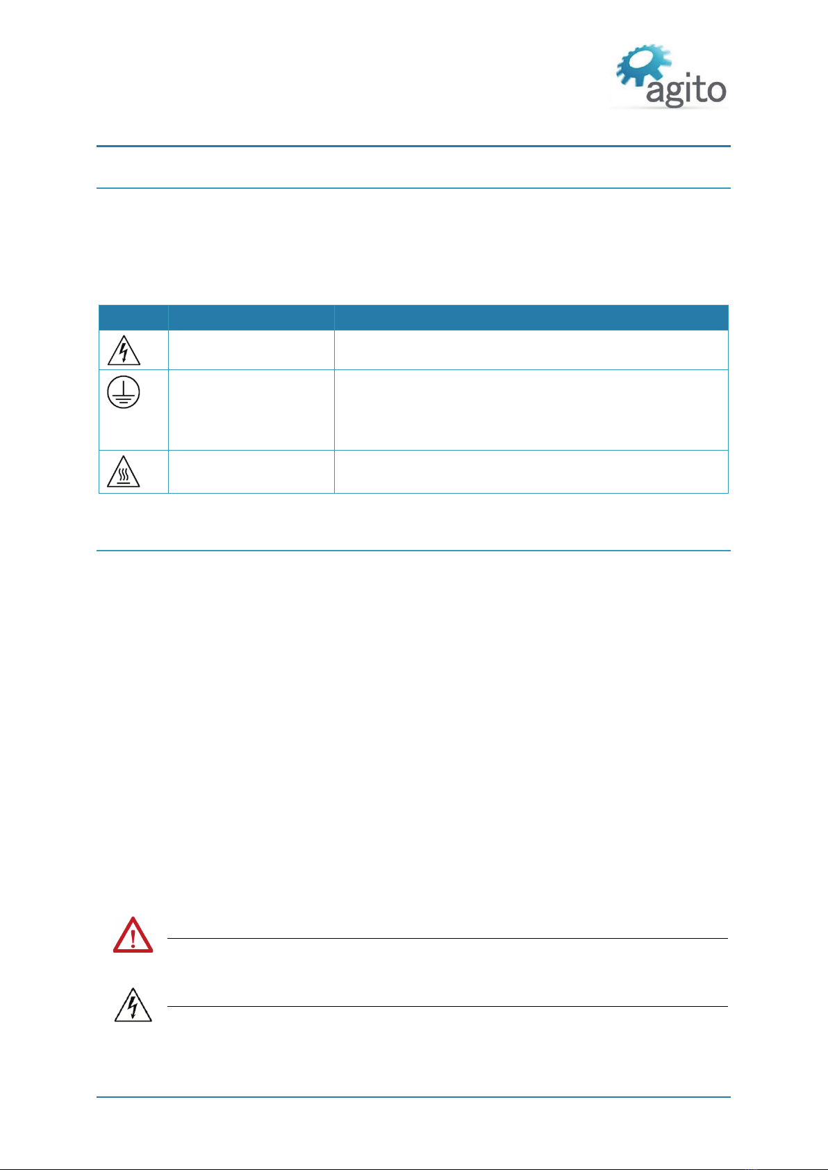
2.1 Safety Symbols __________________________________________________________________ 9
2.2 Safety Guidelines ________________________________________________________________ 9
2.3 Compliance ____________________________________________________________________ 10
3Installation ___________________________________________________________ 11
3.1 Unpacking and Packing___________________________________________________________ 11
3.2 Mounting _____________________________________________________________________ 11
3.2.1 Mounting the AGA155 ____________________________________________________ 11
3.2.2 Mounting Multiple Power Amplifiers ________________________________________ 12
3.3 Electrical Installation ____________________________________________________________ 13
3.3.1 Power Wiring ___________________________________________________________ 13
3.3.2 Regeneration____________________________________________________________ 13
3.3.3 Circuit Breakers__________________________________________________________ 14
3.3.4 AC Line Filter ____________________________________________________________ 15
3.3.5 Safe Operating Area (SOA) _________________________________________________ 15
3.3.6 Grounding ______________________________________________________________ 16
Ground Domains_________________________________________________________ 17
Grounding Policy_________________________________________________________ 17
3.3.7 PT100/PT1000 Temperature Sensors ________________________________________ 17
3.4 Electrical Interfaces _____________________________________________________________ 18
3.4.1 Interface X14: I/O and Brake Power _________________________________________ 18
3.4.2 Interface X15: Safety _____________________________________________________ 19
3.4.3 Interface X7: Motor ______________________________________________________ 21
For Brushless Motor ______________________________________________________ 21
For Brushed (or Voice Coil) Motor ___________________________________________ 21
3.4.4 Interface X8: Static Brake __________________________________________________ 22
3.4.5 Interface X9: Regeneration_________________________________________________ 23
3.4.6 Interface X10: Power _____________________________________________________ 24
3.4.7 Interface X13: Central-i____________________________________________________ 25
3.4.8 Interface X2: Main Encoder ________________________________________________ 26
3.4.9 Interface X4: Halls ________________________________________________________ 27
3.4.10 Interface X5: System I/Os __________________________________________________ 29
I/Os Circuit Diagrams _____________________________________________________ 30
4Operation____________________________________________________________ 33
4.1 Motor Configuration_____________________________________________________________ 33
4.2 Drive/Motor Overload Protection __________________________________________________ 35
4.2.1 I2T Over Load protection __________________________________________________ 35
4.2.2 Motor Stuck ____________________________________________________________ 37
4.2.3 Motor Temperature Protection _____________________________________________ 37
4.3 Tuning ________________________________________________________________________ 38
4.3.1 Commissioning __________________________________________________________ 38
4.3.2 Current Loop Tuning______________________________________________________ 39
4.3.3 Auto Velocity and Position Loop Tuning ______________________________________ 40
4.3.4 Manual Velocity and Position Loop Tuning ____________________________________ 43
5Maintenance and Servicing ______________________________________________ 45

General Description
AGA155 Product Manual Rev.1.3 Page 4
1 Product Description
1.1 General Description
The AGA155 series is a family of 220 VAC remote power
amplifiers.
AGA155 amplifiers are controlled by an AGM series Central-i
master controller, which reads encoder values and current
samples from amplifiers, performs control loops calculation, and
generates PWM commands for each amplifier.
Communication between AGA amplifiers and AGM master is
through a fast Central-i fieldbus, which supports 16 kHz sample
rate motion profiler and all servo loops.
AGA155 amplifiers can power motors up to 10 Arms continuous
and 20 Arms peak current.
The AGA155 amplifier is equipped with digital and analog I/Os
suitable for typical actuators and applications. The digital outputs
are capable of sourcing up to 300 mA or sinking up 500 mA, which
is sufficient for driving most external devices and end effectors,
and eliminates the need for an external relay circuit.
Figure 1. AGA155
1.2 Part Numbering
Product Description Part Number Format
Remote amplifier AGA155-CI-2Axx
CI: Central-i communication
2A: 240 VAC power supply
xx: Continuous and peak current options
03: 3 Arms continuous, 9 Arms peak
06: 6 Arms continuous, 18 Arms peak
10: 10 Arms continuous, 20 Arms peak
Example: AGA155-CI-2A06 indicates 6 Arms continuous, 18 Arms peak current

System Design
AGA155 Product Manual Rev.1.3 Page 5
1.3 System Design
Figure 2. System connections and wiring
Notes
One-phase wiring: AC connects to L1 and L2
Option: 100/300 VDC instead of 120/240 VAC
1.4 Technical Specifications
Electrical/Mechanical Specifications
Feature AGA155-CI-2A03 AGA155-CI-2A06 AGA155-CI-2A10
Number of axes 1
Power supply 1-phase 120/240 VAC, 50-60 Hz
3-phase, 208 VAC, 50-60 Hz
Continuous output current
(Internally limited by firmware)
3 Arms 6 Arms 10 Arms
Peak output current
(Internally limited by firmware)
9 Arms 18 Arms 20 Arms
Output power @ 110 VAC 0.33 kVA 0.66 kVA 1.1 kVA
Output power @ 240 VAC 0.72 kVA 1.44 kVA 2.4 kVA
Input current @ 1-phase 120-240
VAC
4.5 Arms 9 Arms 15 Arms
Input current @ 3-phase 208 VAC 3 Arms 6 Arms 10 Arms
Peak current time 1.5 sec
Output Frequency 0 – 599 Hz
Short-circuit rating Rated short-circuit breaking capacity: 5 kA*

Technical Specifications
AGA155 Product Manual Rev.1.3 Page 6
Feature AGA155-CI-2A03 AGA155-CI-2A06 AGA155-CI-2A10
Isolated digital inputs 8
Isolated digital outputs 2
Bi-directional differential I/Os (RS422)
1
Analog inputs 1 (12-bit optional 16-bit)
Analog outputs N/A
PT100/PT1000 inputs 1
Brake outputs 1
Regeneration outputs 1
Encoder ports 1
Motor types Voice coil, brushed or brushless linear or rotary motor.
2-phase steppers (open and closed loop, micro-stepping)
Communication Central-i
PWM Frequency 16 kHz
Power supply to external devices Voltage: 5V
Overall max. current: 1.5A
Maximum leakage current 6 mA
Encoder Ports Specifications
Feature Specification
Encoder types Incremental AqB, Sin/Cos
Absolute: EnDat 2.2, BiSS-C
Power supply to encoder 0.5 A per encoder port
Max. cable length 40 m
Incremental encoder Hardware: Differential RS422/RS485
Max. input frequency: 6.25 MHz
Termination: 120 W
Commutation: Auto-phasing, Hall sensors
Sin/Cos encoder Hardware: Differential RS422/RS485, 1V pk-pk @2.5V
Max. input frequency: 250 kHz
Termination: 120 W
Max interpolation: 13 bits (x 8192)
Commutation: Auto-phasing, Hall sensors
Absolute BiSS-C Hardware: Differential RS422/RS485, clock (MA), data (SLO)
Clock frequency: 1 MHz
Max. position bits: 32 bits
Commutation: Auto-phasing, by absolute offset
Absolute EnDat 2.2 Hardware: Differential RS422/RS485, clock, data
Clock frequency: 1 MHz
Max. position bits: 32 bits
Commutation: Auto-phasing, by absolute offset
Hall sensors Opto-isolated 5V with internal or external power supply

Technical Specifications
AGA155 Product Manual Rev.1.3 Page 7
I/O Specifications
Feature Specification
Power supply for optically isolated
I/Os
Voltage: 5-28 VDC
Optically isolated digital inputs Type: PNP/NPN
Propagation delay: 10 µs
Max. frequency: 100 kHz
Functionality: limit switches, home, captures, start motion,
gain scheduling, and others
Optically isolated digital outputs Type: PNP/NPN
Max current: 0.5A (for NPN type), 0.3A (for PNP type)
Propagation delay: 10 µs
Max. frequency: 100 kHz
Functionality: alarm, in-position, event (PEG), and others
Differential digital inputs Hardware: Differential RS422
Propagation delay: 100 ns
Max. frequency: 2 MHz
Functionality: lock (capture), pulse and direction, Handwheel
Analog inputs Operational voltage: ±10V
Resolution: 12 bit
Analog outputs N/A
Static brake output Operational voltage: 24V
Maximum current: 3A
Temperature sensors inputs PT100 or PT1000. Refer to the section PT100/PT1000
Temperature Sensors.
Central-i Specifications
Feature Specification
Topology Star (peer to peer)
Cycle time 61 µs
Connector type RJ-45 (Cat5e cable)
Cable length Up to 100m
Physical layer Dual channel RS485 full duplex
Baud rate 20 Mbps (per channel)
Synchronization between nodes 8 nanosecond
Dimensions and Weight
Feature Specification
Unit dimensions (max) H=196.97 mm, W=65.80 mm, D=158.60 mm
Package dimensions 244 mm x 92 mm x 198 mm
Unit weight 1.29 kg
Shipping weight 1.44 kg

Environmental Specifications
AGA155 Product Manual Rev.1.3 Page 8
Figure 3. Product dimensions (mm)
1.5 Environmental Specifications
Environmental Specifications
Feature Specification
Operating temperature* AGA155-CI-2A03: 0°C to 50°C
AGA155-CI-2A06: 0°C to 50°C
AGA155-CI-2A10: 0°C to 40°C
Storage temperature -20°C to 70°C
Operating humidity < 90%
Storage humidity < 40%
Pollution degree 2
Vibration 1G @ 150 Hz according to IEC 60068-2-6
Operating conditions Protection class: IP20
* The operational range may be additionally limited by the internal temperature protection of the
product. Refer to the section Safe Operating Area (SOA). However, it is the user’s responsibility to
avoid operating the product in environmental conditions that do not conform to the defined limits.

Safety Symbols
AGA155 Product Manual Rev.1.3 Page 9
2 Safety
2.1 Safety Symbols
Safety symbols indicate a potential for personal injury or equipment damage if the prescribed
precautions and safe operating practices are not followed.
The following safety symbols are used in the product documentation.
Safety Symbols
Symbol Meaning Description
Hazardous voltage Indicates hazards arising from dangerous voltages.
Earthing PE
(protective earth)
Identifies any terminal which is intended for connection to an
external conductor for protection against electric shock in
case of a fault, or the terminal of a protective earth (ground)
electrode.
Caution, hot surface Indicates the marked item can be hot and should not be
touched without taking care.
2.2 Safety Guidelines
To achieve optimum and safe operation of the product, it is important to follow the safety
procedures specified in this manual.
Only qualified personnel may install, maintain, or repair the product. Before starting installation,
maintenance or operation, ensure that all system components are connected to protective earth
ground (PE).
The PE wire must be colored green-yellow, in accordance with local electrical wiring standards.
This product contains electrostatic-sensitive components. Proper handling procedures must be
observed to avoid damage to the product.
To avoid electric arcing and hazards, never connect or disconnect any connector while the power
source is on.
The maximum power supply voltage connected to the product must comply with the ratings
provided in this manual.
Always disconnect the power cables before servicing the product.
Pay attention to safety symbols on the product or in the manual. Follow proper safety precautions
when installing or operating the product.
Attention
All power connectors must be securely tightened before any operation.
Warning
Connectors X10, X9, and X7 are high power. Do not touch these connectors when the
product is powered.

Compliance
AGA155 Product Manual Rev.1.3 Page 10
Warning
Capacitors on the DC bus can retain hazardous voltages after input power has been
removed. Discharge time to below 75 VDC is 40 minutes.
Wait until the red LED (Charge indicator) shuts off before physically touching the
product. The product must not be opened or serviced until the discharge is complete.
Failure to observe this precaution could result in severe bodily injury or loss of life.
Attention
Do not attempt to hinder or override the product’s or system’s fault detection or
protection circuits. You must determine the cause of a fault and correct it before you
attempt to operate the system. Failure to correct the fault could result in personal
injury and/or damage to equipment.
2.3 Compliance
Standards Compliance
Description Standard
Safety requirements – Electrical, thermal and energy IEC-61800-5-1
EMC requirements and specific test methods IEC-61800-3
This product is intended to operate in a machine or equivalent end-product. The machine or end-
product must comply with any necessary safety standard as typically required for the same type of
machine or end-product. It is the responsibility of the machine or end-product manufacturer to
ensure the final machine or end-product meets the requirement of any safety and EMC regulations.

Unpacking and Packing
AGA155 Product Manual Rev.1.3 Page 11
3 Installation
3.1 Unpacking and Packing
Save the original box and packing materials in case you need to pack and return the product to the
manufacturer.
To unpack the product:
1. Carefully remove the product from the box and the packing materials.
2. Visually inspect the product to ensure that there is no damage. If any damage has occurred,
report it immediately to the carrier that delivered the package.
3. After unpacking, locate the part number label on the product, and make sure it matches the
product your ordered, and that the voltage meets your specific requirements.
3.2 Mounting
3.2.1 Mounting the AGA155
The heatsink on the back of the AGA155 includes a hole (at top) and a slot (at bottom) for mounting
the unit. The AGA155 must be mounted vertically (book mounting), as shown in Figure 3.
The AGA155 is mounted using 2 M4 screws. It is important to mount the product on metal panel for
both grounding and secure connections.
The heatsink of the AG155 is electrically conductive and serves as the protective earth (PE) ground of
the product. However, it is critical to ensure the PE screws are electrically conducting between the PE
of AGA155 and the PE of main power supply in the system.
All cables connected to the product must be securely constrained to avoid vibration that causes
stress concentration at the cables or connectors which may result in breakage of electrical
conductivity.
Warning – Metal Base Plate for Heat Dissipation
The product is supplied with the mounting plate built into the heatsink. At full power
operation, the heat sink can be quite warm, around 45°C. It is recommended to mount
the product on a large metal panel to help dissipate the heat generated in the product.

Mounting
AGA155 Product Manual Rev.1.3 Page 12
3.2.2 Mounting Multiple Power Amplifiers
When mounting multiple amplifiers within a cabinet, clearance between units must be at least
10 mm. In addition, top and bottom clearance must be at least 50 mm.
Ambient temperature in the cabinet must not exceed the limit defined in section Safe Operating Area
(SOA).
If amplifiers are mounted on a backplane, the backplane temperature must not exceed the limit
defined section Safe Operating Area (SOA).
It is recommended to install a cooling fan at the bottom of the cabinet for best circulation.
Figure 4. Mounting multiple amplifiers within cabinet

Electrical Installation
AGA155 Product Manual Rev.1.3 Page 13
3.3 Electrical Installation
3.3.1 Power Wiring
AGA155 is designed to operate directly from 110 VAC to 240 VAC mains power, which is supplied to
bus voltage, to motor, and to logic power.
Logic power input (L1C, L2C) uses 1-phase 120 VAC to 240 VAC input.
Motor power input (L1, L2, L3) uses either of the following:
1-phase 120-240 VAC input
3-phase 208 VAC input
Note – Wiring
In single phase wiring, L1 and L2 must be wired to 1-phase 110/240 VAC.
In three phase wiring, L1, L2 and L3 must be wired to 3-phase 110/240 VAC.
3.3.2 Regeneration
AC power input is converted to DC bus, and outputs a controlled electrical power through the phases
of the motor. The motor converts this electrical power to a mechanical power that moves the load.
During motor deceleration and stopping, the inertia of the load drives the movement of the motor,
not the servo drive. Due to back EMF, the motor acts as a generator and returns energy to the DC bus
supply, which causes the DC bus voltage to increase to undesirable level.
Maximum allowable DC bus voltage is 400 VDC. To control the DC bus voltage, a regeneration
resistor can be connected to the servo drive to dissipate excess regenerated energy, and prevent it
from reaching undesirable levels. The regeneration resistor starts to dissipate energy at 370 VDC .
Warning
DC Vbus is monitored, and motors will be disabled if voltage is too high. However, there
is no protection against the connection of an excessive voltage power supply that will
damage the product.
For connection details, refer to the section Interface X9: Regeneration.
Important Notes:
The regeneration feature, once enabled, is always active, regardless of the motor status
(enabled/disabled).
Current will flow in the regeneration resistor depending on the values of RegenOn and RegenOff,
and the power supply voltage.
There are no current or power protections to protect the regeneration resistor or the internal
MOSFET.
Be sure to set the suitable regeneration parameters for the supply voltage and the external
regeneration resistor.
Plug in the regeneration resistor only after all parameters are set properly, and always when the
controller power is off.
Let the regeneration resistor cool down before touching it. Unplug it only when the controller
power is off.

Electrical Installation
AGA155 Product Manual Rev.1.3 Page 14
During development, if the supply voltage is to be modified, first disconnect the regeneration
resistor and, before reconnecting the regeneration resistor, be sure to adjust the regeneration
parameters to match the new supply voltage.
We recommend adding external protections (such as PTC) to protect the regeneration resistor.
Figure 5. Power supply wiring
3.3.3 Circuit Breakers
Circuit Breaker Specifications
Feature Specification
Circuit breaker type Type C. 2-pole for L to N. 3-pole for 3-phase.
Fuse type Time delay / slow blow
Current rating AGA155 10A: 25 A
AGA155 6A: 10 A
AGA155 3A: 6 A
Voltage rating AC 600 VAC
Interrupt rating minimum 10 kA
Example: circuit breaker: SE iC60N 3P 6A C

Electrical Installation
AGA155 Product Manual Rev.1.3 Page 15
3.3.4 AC Line Filter
For proper product operation, an external AC line filter is required. Refer to Figure 5. Power supply
wiring. The AC line filter prevents external transients and spikes on the power line from entering the
product enclosure. Such interference may be caused by other AC powered devices being turned on
and off, and by motors running on the same power subsystem.
AC Line Filter Specifications
Feature Specification
Filter type 2 stage AC line filter
Current 20 Amp
Voltage 250 VAC
Antennation frequency From 100Khz to 50 MHz
Example: Wurth 810913020
3.3.5 Safe Operating Area (SOA)
While each specific maximal rating can be safely used, the product cannot support certain
combinations of these maximal ratings. For example, the product will not enable operation under the
following combined maximal ratings usage continuously over long-term period:
Continuous current at 6Arms, at 90% PWM duty cycle
1.5A external load on the 5V supply
Product mounted horizontally and not attached to a suitable base plate
55°C ambient temperature
Permitted combinations, as well as forbidden combinations, cannot be specifically provided since
they are a function of multiple conditions, such as continuous current, bus voltage, PWM duty cycle,
5V consumption, I/O's high current usage, mounting base plate size, product mounting orientation,
and ambient temperature.
The SOA of the product is defined as any combination of operational conditions (each within the
absolute maximal ratings defined in Section) and assembly options that lead to internal product
temperature below 80°C.
The product includes a built-in temperature sensor. Its internal temperature is reported via the
status parameter PwrTemp (integrated power module temperature). When PwrTemp reaches 80°C,
the motor will be disabled and an error will be reported. A motor-enable request will create an error
if PwrTemp is higher than 80°C.
The following figure shows examples of safe operating cases for AGA155-CI-2A06. The SOA charts
assume 90% duty cycle on PWM output continuously; that is, motors are moving at the maximum
speed allowed by the bus voltage.

Electrical Installation
AGA155 Product Manual Rev.1.3 Page 16
Figure 6. Current/Temperature
Attention
Each of the power/voltage/current absolute maximal ratings is valid over the overall
operating temperature range, subject to the safe operating area (SOA) .
Attention
Operating (or storing) the product contrary to the defined absolute maximal ratings is
not allowed and will damage the product.
3.3.6 Grounding
It is recommended to install the AGA155 on a metal plate for better power dissipation, reduced EMI,
and grounding connection. Make sure the plate is not painted.
The heatsink of the AGA155 is electrically conductive and serves as the protective earth (PE) ground
of the product. However, it is critical to ensure the PE screws are electrically conducting between the
PE of AGA155 and the PE of main power supply in the system.
Figure 7. System grounding

Electrical Installation
AGA155 Product Manual Rev.1.3 Page 17
Ground Domains
The following table shows the ground domains in the AGA155 system:
GND. Reference voltage for digital/analog circuits and signals.
PGND. High voltage ground domain (internal)
General. Usually at DC potential close to GND, but not connected internally.
Ground Domains
Name
Ground Domain
Notes
DC power input
GND (I/O return)
External DC power supply
AC power input PGND (power ground only) Internal PGND
Central-i communication GND (for master) Isolated for Central-i remote
devices
Isolated digital inputs/outputs General Isolated
Differential inputs/outputs
(not isolated)
GND
Analog inputs/outputs (not isolated)
GND
Brake control output General External DC power supply
Regeneration output PGND
Grounding Policy
Grounding of the product must comply with the following guidelines:
The enclosures and other external parts that may be touched by the user are in the safe domain.
The AGA155 must be connected to protective earth (PE) and connected to the building’s ground.
PE is protected with an earth-leakage circuit breaker (ELCB); hence it is safe to touch. Refer to
Figure 7.
PGND is connected directly to mains wires, hence it is just as dangerous as mains to the user.
All shielded cables, including but not limited to motor, encoders, and power input, have their
shield connected to PE as part of the external metal enclosure.
PGND is bypassed to PE with low capacitance (around 10 nF) for EMI/EMC purposes.
It is critical to avoid ground loops in the system. A ground loop allows currents to return by two
or more different paths, causing electromagnetic interference or even damage to wires.
The system designer must carefully examine all GND connections in the system to ensure that no
loops are created, and that all GND-referenced signals have a GND wire nearby (for both return
currents and common mode voltage).
3.3.7 PT100/PT1000 Temperature Sensors
AGA155 supports two types of temperature sensors:
The PT100 temperature sensor is a platinum resistance thermometer. Its resistance value at 0°C
is 100Ω.
The PT1000 temperature sensor also a platinum resistance thermometer. Its resistance value at
0°C is 1000Ω.
The temperature sensor is wired to the X4 connector as shown in the following table.

Electrical Interfaces
AGA155 Product Manual Rev.1.3 Page 18
PT100/PT1000 Temperature Sensor Wiring
Pin # Pin Name PT100 PT1000
3 PT1000_EN NC Short to pin 6
6 GND NC Short to pin 3
8 RTD+ PT100+ PT1000+
9 RTD- PT100- PT1000-
3.4 Electrical Interfaces
This section provides a detailed description of all the power and signal interfaces of the product.
3.4.1 Interface X14: I/O and Brake Power
This connector allows user to provide DC power supply to the isolated I/Os and motor brake.
Typically, the isolated I/Os use 24 VDC. The I/O power is internally connected to each I/O port to
allow users to tap this power supply easily within the same connector.
The brake power supports up to 48 VDC. This power is internally connected to the brake output port.
Figure 8. I/O and Brake Power Connector
Connector X14: I/O PWR
Pin # Name Description
1 IO_PWR 5–24 VDC – user supplied I/O power input, up to 2A
2 IO_PWR_Return Ground – I/O power return
3 VBrake 12–48 VDC – brake power input, up to 70W
4 VBrake_Return Ground – brake power return
Connector manufacturer Phoenix Contact
Mating connector part number 1966114
(Wurth Electronics equivalent: 691364100004)
(Degson equivalent: 15EDGKDM-3.5-04P-14)
Connector pitch 3.5 mm
Wiring AWG 18, insulation rated for 100V

Electrical Interfaces
AGA155 Product Manual Rev.1.3 Page 19
Warning - Hot plugging is forbidden!
Plug or unplug the power connector only when power is off! Plugging the power
connector when power is on may cause power surges through connected devices and
possibly damage them.
3.4.2 Interface X15: Safety
Figure 9. Safety Connector
Connector X15: SAFETY
Pin # Name Description
1 5V 5V supply for safety circuits
2 Safety_Feedback- Safety_Feedback negative (emitter) output
3 Safety_Input_2- Safety_Input_2 negative input
4 Safety_Input_1- Safety_Input_1 negative input
5 GND GN
6 Safety_Feedback+ Safety_Feedback positive (collector) output
7 Safety_Input_2+ Safety_Input_2 positive input
8 Safety_Input_1+ Safety_Input_1 positive input
Connector manufacturer Samtec Inc.
Mating connector part number IPD1-04-D-K
Crimp contact part number CC79L-2630-01-L (or equivalent)
Wiring 26 AWG, insulation rated for 100V

Electrical Interfaces
AGA155 Product Manual Rev.1.3 Page 20
Safety connector circuit diagram
Figure 10. Electrical Interfaces – Safety Connector
Safety_Input_1 and Safety_Input_2 function independently, thus providing safety redundancy.
Each one can disable the power to the motor.
Both Safety_Input_1 and Safety_Input_2 disable the power to the motor through hardware
circuitry, without any software intervention.
Both Safety_Input_1 and Safety_Input_2 are defined with a positive pin (+) and a negative pin (-).
However, the opto-coupler at the Safety_Input has two input diodes, which enable operation at
"positive" or "negative" input voltage. The input is activated when current is sufficient at one of
the input diodes, regardless of the current direction. This enables NPN or PNP connection to the
safety inputs.
The Safety_Input protection logic is designed so that both Safety_Inputs must be powered to
enable motor operation. Leaving a Safety_Input disconnected prevents motor operation. This
logic is required to ensure that a disconnected safety cable is considered an unsafe condition by
the control unit. When sufficient current is driven through a Safety_Input, the state of this input
is Safe. When insufficient current is driven through a Safety_Input, the state of this input is
Unsafe.
The two Safety_Inputs must be in the Safe state to enable motor operation.
Both Safety_Input_1 and Safety_Input_2, although acting on the drive hardware directly, are also
monitored by the controller software. The controller software generates a feedback signal to the
user (Safety_Feedback), which is also an isolated signal. This feedback is generated by the
software, and is activated if at least one of Safety_Input_1 or Safety_Input_2 signals is in the
Unsafe state.
The electrical characteristics of the Safety_Input_1 and Safety_Input_2 are identical to those of
all other isolated digital inputs of the controller.
The safety inputs implemented in the product are currently pending certification Functional
Safety Standards.
Table of contents
Other Agito Amplifier manuals