Agrimate AM-400-PRO-4S User manual

User Manual
BEFORE OPERATING THIS MACHINE,
PLEASE READ THESE INSTRUCTIONS CAREFULLY
DISCLAIMER: DUE TO CONSTANT UPGRADATION, FEATURES AND SPECIFICATIONS ARE
SUBJECT TO CHANGE WITHOUT NOTICE
OPERATION AND MAINTENANCE MANUAL
AM-400-PRO-4S
BRUSH CUTTER

2
SAFETY FIRST
Instructions contained in warnings within this manual marked with a symbol concern critical points which must be
taken into consideration to prevent possible serious bodily injury, and for this reason you are requested to read all such
instructions carefully and follow them without fail.
1. Parts Identification
2. Specifications
3. Warning labels on the machine
4. Symbols on the machine
5. For safe operation
6. Set up
7. Fuel
8. Operation
9. Maintenance
10. Storage
11. Troubleshooting guide
WARNING
This mark indicates instructions, which must be followed in order to prevent accidents, which could lead to serious bodily
injury or death.
IMPORTANT
This mark indicates instructions, which must be followed, or it leads to mechanical failure, breakdown, or damage.
NOTE
This mark indicates hints or directions useful in the use of the product.
WARNINGS IN THE MANUAL
CONTENTS

3
PARTS LOCATION
1 Primer pump
2 Air cleaner cover
3 Choke lever
4 Fuel tank
5 Starter knob
6 Blade
7 Gear case
8 Debris guard
9 Loop handle
10 Drive shaft housing
11 Shoulder strap hanger
12 Throttle lever
13 Ignition switch
14 Throttle cable
15 Protector (Optional)
16 Handle
17 Throttle interlock
18 Half-throttle lock
11
12
13
14
1
2
3
4
5
6
78
10
16
15
17
18

4
SPECIFICATION
Read owner’s manual before
operating this machine.
Wear head, eye and ear
protection.
Warning / Attention
Keep all children, bystanders
and helpers 15 meters away
from the machine.
If warning label peels off
or becomes soiled and
impossible to read, you
should contact the dealer
from which you purchased
the product to order new
labels and affix them in the
required location(s).
Never modify your machine.
We won’t warrant the
machine, if you use there
modeled brush Cutter or if
you don’t observe the proper
usage written in the manual.
WARNING LABELS ON THE MACHINE
Note:
Specifications may be vary according to the types, and are subject to change without notice.
Model AM 400-PRO-4S
Engine AM 39
Engine type 4-stroke, nickel plated cylinder, 1 cylinder
Displacement 38.8cm3
Bore × Stroke 40 × 30.9 mm
Max. output 1.1 KW /8000pm
Max. torque 1.9Nm/ 5,500 rpm
Max. rotation with no load 10,000 rpm
Fuel consumption 360 g/kwh(265g/PSh)
Cooling system Forced air
Ignition system Transistor magneto
PTO shaft rotation Counter clockwise
Oil Capacity 80 ML
Fuel tank Capacity 600 ML

5
SYMBOLS ON THE MACHINE
For safe operation and maintenance, symbols are carved in relief on the machine. According to these indications, please
be careful not to make a mistake.
The port to refuel the “MIX GASOLINE”
Position: FUEL TANK CAP
The direction to close the choke
Position: AIR CLEANER COVER
The direction to open the choke
Position: AIR CLEANER COVER
FOR SAFE OPERATION
1. Read this manual carefully until you completely understand and follow all safety and operating
instructions.
2. Keep this manual handy so that you may refer to it later whenever any questions arise. Also note,
if you have any questions which cannot be answered herein, contact the dealer from whom you
purchased the product.
3. Always be sure to include this manual when selling, lending, or otherwise transferring the
ownership of this product.
4. Never allow children or anyone unable to fully understand the directions given in the manual to
use the machine.
WORKING CONDITION
1. When using the product, you should wear proper clothing and protective equipment.
(1) Helmet
(2) Ear protectors
(3) Protection goggles or face protector
(4) Thick work gloves
(5) Non-slip-sole work boots
2. And you should carry with you.
(1) Attached tools
(2) Properly reserved fuel
(3) Spare blade
(4) Things to notify your working area (rope, warning signs)
(5) Whistle (for collaboration or emergency)
(6) Hatchet or saw (for removal of obstacles)

6
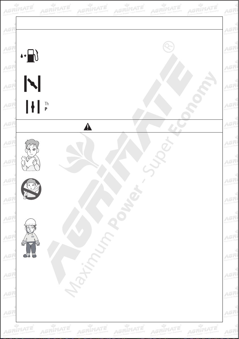
3. Do not wear loose clothing,
jewelry,short trousers, sandals, or
go barefoot. Do not wear anything
which might be caught by a
moving part of the unit. Secure
hair so it is above shoulder length.
WORKING CIRCUMSTANCE
1. Never start the engine inside a
closed room or building. Exhaust
gases contain dangerous carbon
monoxide.
2. Never use the product,
a. when the ground is slippery
or when you can’t maintain
a steady posture.
b. At night, at times of heavy
fog,or at any other times
when your field of vision
might be limited and it
would be difficult to gain a
clear view of the working
area.
c. During rain storms, during
lightning storms, at times of
strong or gale-force winds,
or at any other times when
weather conditions might
make it unsafe to use the
product.
WORKING PLAN
1. You should never use the product
when under the influence of
alcohol, when suffering from
exhaustion or lack of sleep,
when suffering from drowsiness
as a result of having taken cold
medicine or at any other time
when a possibility exists that
your judgment might be impaired
or that you might not be able to
operate the product properly and
in a safe manner.
2. When planning your work
schedule,allow plenty of time
to rest. Limit the amount of time
over which the product is to be
used continuously to somewhere
around 30 ~ 40 minutes per
session,and take 10 ~ 20 minutes
of rest between work sessions.
Also try to keep the total amount
of work performed in a single day
under 2 hours or less.
WARNING
1. If you don’t observe the working
time, or working manner
(See“USING THE PRODUCT”),
Repetitive Stress Injury (RSI) could
occur.
If you feel discomfort, redness
and swelling of your fingers or
any other part of your body, see a
doctor before getting worse.
2. To avoid noise complaints,
in general,operate product
between8 a.m. and 5 p.m. on
weekdays and 9 a.m. to 5 p.m. on
weekends.
NOTE
Check and follow the local regulations as to sound
level and hours of operations for the product.
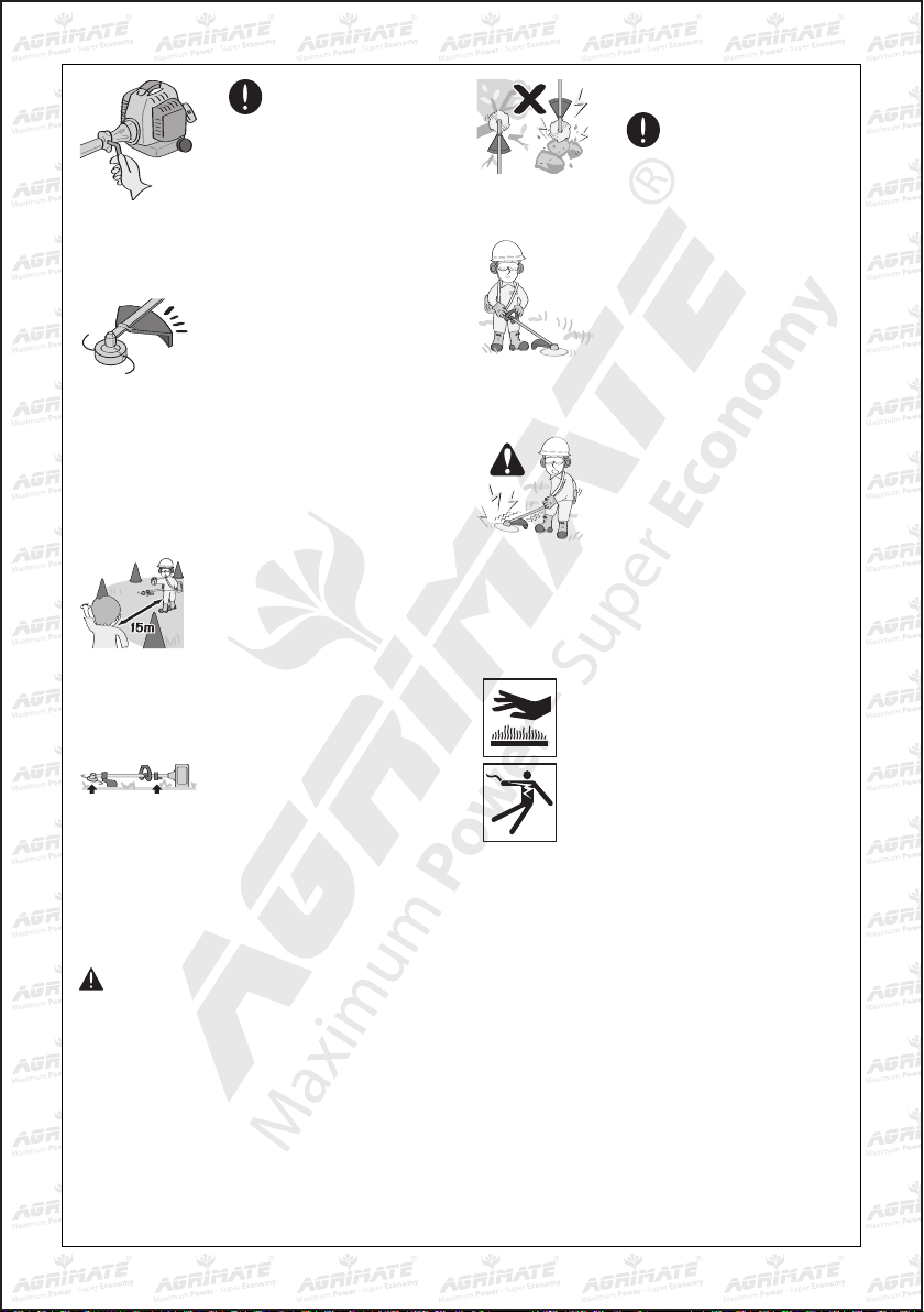
BEFORE STARTING THE ENGINE
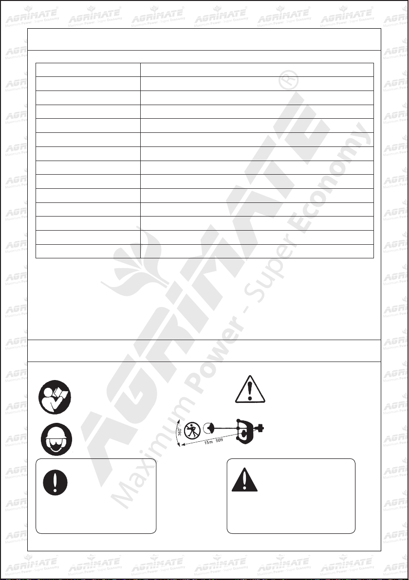
1. The area within a perimeter
of15 m (50 ft) of the person
using the product should be
considered a hazardous area
into which no one should enter.
If necessary,yellow warning
rope, warning signs should be
placed around the perimeter of
the area. When work is to be
performed simultaneously by
two or more persons,care should
also be taken to constantly look
around or otherwise check for the
presence and locations of other
people working so as to maintain
a distance between each person
sufficient to ensure safety.
2. Check the condition of working
area to avoid any accident by
hitting hidden obstacles such as
stumps, stones, cans, or broken
glass.

7
USING THE PRODUCT
IMPORTANT
Cut only materials recommended
by the manufacturer. And use only
for tasks explained in the manual.
1. Grip the handles firmly with both
hands using your whole hand.
Place your feet slightly apart
(slightly further apart than the
width of your shoulders) so that
your weight is distributed evenly
across both legs, and always be
sure to maintain a steady, even
posture while working.
2. Keep cutting attachment below
waist level.
3. Maintain the speed of the engine
at the level required to perform
cutting work, and never raise the
speed of the engine above the
level necessary.
4. If the unit starts to shake or
vibrate, turn off the engine and
check the whole unit. Do not use it
until the trouble has been properly
corrected.
5. Keep all parts of your body away
from rotating cutting attachment
and hot surfaces.
6. Never touch the muffler, spark
plug, or other metallic parts of
the engine while the engine is in
operation or immediately after
shutting down the engine. Doing
so could result in serious burns or
electrical shock.
IF SOMEONE COMES
1. Guard against hazardous
situations at all times. Warn
adults to keep pets and children
away from the area. Be careful if
you are approached. Injury may
result from flying debris.
2. If someone calls out or otherwise
interrupts you while working,
always be sure to turn off the
engine before turning around.
IMPORTANT
Remove any obstacle before
beginning work.
3. Inspect the entire unit for loose
fasteners and fuel leakage. Make
sure that the cutting attachment
is properly installed and securely
fastened.
4. Be sure the debris guard is firmly
attached in place.
5. Always use the shoulder strap.
Adjust the strap for comfort
before starting the engine. The
strap should be adjusted so the
left hand can comfortably hold
the handlebar grip approximately
waist high.
STARTING THE ENGINE
1. Keep bystanders and animals
at least 15 m (50 ft) away from
the operating point. If you are
approached, immediately stop the
engine.
2. The product is equipped with a
centrifugal clutch mechanism, so
the cutting attachment begins to
rotate as soon as the engine is
started by putting the throttle into
the start position. When starting
the engine, place the product onto
the ground in a flat clear area
and hold it firmly in place so as
to ensure that neither the cutting
part nor the throttle come into
contact with any obstacle when
the engine starts.
WARNING
Never place the throttle into the high-speed position
when starting the engine.
3. After starting the engine, check to make sure that
the cutting attachment stops rotating when the
throttle is moved fully back to its original position.
If it continues to rotate even after the throttle has
been moved fully back, turn off the engine and take
the unit to your dealer for repair.

8
MAINTENANCE
1. In order to maintain your product in proper working order, perform the maintenance and checking
operations described in the manual at regular intervals.
2. Always be sure to turn off the engine before performing any maintenance or checking
procedures.
WARNING
The metallic parts reach high temperatures immediately after stopping the engine.
3. When replacing the cutting attachment or any other part, or when replacing the oil or any
lubricant,always be sure to use only qualified products.
4. In the event that any part must be replaced or any maintenance or repair work not described in
this manual must be performed, please contact your dealer for assistance.
5. Do not use any accessory or attachment other than those recommended for the unit.
6. Under no circumstances shou ld you ever take apart the product or alter it in any way. Doing so
might result in the product becoming damaged during operation or the product becoming unable
to operate properly.
HANDLING FUEL
1. The engine of the product is designed to run on a mixed fuel, which contains highly flammable
gasoline. Never store cans of fuel or refill the tank of the unit in any place where there is a
boiler, stove,wood fire, electrical sparks, welding sparks, or any other source of heat or fire
which might ignite the fuel.
2. Never smoke while operating the unit or refilling its fuel tank.
3. When refilling the tank, always turn off the engine and allow it to cool down. Take a careful look
around to make sure that there are no sparks or open flames anywhere nearby before refueling.
4. Wipe spilled fuel completely using a dry rag if any fuel spillage occurs during refueling.
5. After refueling, screw the fuel cap back tightly onto the fuel tank and then carry the unit to a
spot 3 more away from where it was refueled before turning on the engine.
TRANSPORTATION
1. When hand-carrying the product,cover over the cutting part if necessary, lift up the product and
carry it paying attention to the blade.
2. Never transport the product over rough roads over long distances by vehicle without removing
all fuel from the fuel tank. If doing so,fuel might leak from the tank during transport.

9
SET UP
INSTALLING HANDLE (BCG1E34F)
• Mountthehandletotheshafttubeandclampitata
location that is comfortable to you.
INSTALLING HANDLE (BCG1E40F-5)
1. Loosen the 4 bolts on the upper cap and insert the
handles equally. Retighten the bolts.
2. Put the handle assembly into the bracket and put the
upper cap over it. Tighten the cap securely.
INSTALLING DEBRIS GUARD FOR LINE HEAD
• Attach the debris guard with the bolts provided
while inserting the spacer between the guard and
the pipe.
MOUNTING THE 3 OR 4 TEETH BLADE
Always switch off the engine and disconnect the
spark plug cap before mounting metal cutter blades!
C
- Remove the cotterpin
- Unscrew the locknut (C/7) from the shaft by turning
it clockwise. If necessary, block the angle gear (see
below).
NOTE
The locknut is provided with a left-hand thread!
- Remove oating disc (C/6) and thrust washer (C/5).
- Insert the o set screwdriver 4 mm (C/1) through the
winding guard and the locking disc into the opening
(C/3) in the angular gear (block the winding gear). If
necessary turn the mounting disc (C/3) slightly.
Position the blade (C/4), thrust washer (C/5) and
finally the floating disc (C/6) as shown.
- Screw down the locknut (C/7) and tighten it by
turning the combination wrench counter-clockwise.
Caution: For safety reasons, after every 10 tool changes
the locknut (C/7) must be replaced with a new one.
- Put back the cotter pin.
- Remove Allen key and check for freedom of motion
of the cutting tool.
INSTALLING THE TRIMMER HEAD
Always switch off the engine and nect the spark plug cap
mounting the trimmer head!
D
- Place the mounting disc (D/3) on the shaft.
- Insert the 4 mm Allen key (D/1) through the
winding guard and the mounting disc (D/3) into the
opening on the angle gear (blocks the angle gear). If
necessary turn the mounting disc (D/3) slightly.
- Screw the trimmer head (D/2) onto the shaft by
turning it counter-clockwise.
- Now tighten the trimmer head by hand.
- Remove the Allen key and check for freedom of
motion of the trimmer head.

10
BALANCE UNIT
1. Put on strap and attach unit to strap.
2. Slide clamp up or down until unit balances with
head aparting from the ground when using it.
WARNING
• Gasoline is very flammable. Avoid smoking or
bringing any flame or sparks near fuel. Make
sure to stop the engine and allow it cool
before refueling the unit. Select outdoor bare
ground for fueling and move at least 3 m (10 ft)
away from the fueling point before starting the
engine.
• The engines are lubricated by oil specially
formulated for air-cooled 2-cycle gasoline engine
use.
Use an anti-oxidant added quality oil expressly
labeled for air-cooled 2-cycle engine use (JASO FC
GRADE OIL or ISO EGC GRADE).
• DonotuseBIAorTCW(2-strokewater-coolingtype)
mixed oil.
RECOMMENDED MIXING RATIO GASOLINE 25:OIL 1
Exhaust emission are controlled by the fundamental
engine parameters and components (eq.,
carburetion, ignition timing and port timing) without
addition of any major hardware or the introduction
of an inert material during combustion.
INSTALLING DEBRIS GUARD FOR METAL BLADE
• Whenusingmetalblade,makesuretoremovethe
guard skirt.
FUEL
• Theseenginesarecertiedtooperateonunleaded
gasoline.
• Makesuretousegasolinewithaminimumoctane
number of 89RON (USA/Canada: 87AL).
• If you use a gasoline of a lower octane value
than prescribed, there is a danger that the engine
temperature may rise and an engine problem such
as piston seizing may consequently occur.
• Unleaded gasoline is recommended to reduce the
contamination of the air for the sake of your health
and the environment.
• Poorqualitygasoline’soroilsmaydamagesealing
rings, fuel lines or fuel tank of the engine.
HOW TO MIX FUEL
WARNING
Pay attention to agitation.
1. Measure out the quantities of gasoline and oil to be
mixed.
2. Put some of the gasoline into a clean, approved fuel
container.
3. Pour in all of the oil and agitate well.
4. Pour in the rest of gasoline and agitate again for
at least one minute. As some oils may be difficult
to agitate depending on oil ingredients, sufficient
agitation is necessary for the engine to last long.
Be careful that, if the agitation is insufficient, there
is an increased danger of early piston seizing due to
abnormally lean mixture.
5. Put a clear indication on the outside of the container
to avoid mixing up with gasoline or other containers.
6. Indicate the contents on outside of container for
easy identification.

11
OPERATION
FUELING THE UNIT
1. Untwist and remove the fuel cap. Rest the cap on a
dustless place.
2. Put fuel into the fuel tank to 80% of the full capacity.
3. Fasten the fuel cap securely and wipe up any fuel
spillage around the unit.
WARNING
1. Select bare ground for fueling.
2. Move at least 10 feet (3 meters) away from the
fueling point before starting the engine.
3. Stop the engine before refueling the unit. At that
time, be sure to sufficiently agitate the mixed
gasoline in the container.
FOR YOUR ENGINE LIFE, AVOID
1. FUEL WITH NO OIL (RAW GASOLINE) – It will cause
severe damage to the internal engine parts very
quickly.
2. GASOHOL – It can cause deterioration of rubber
and/or plastic parts and disruption of engine
lubrication.
3. OIL FOR 4-CYCLE ENGINE USE – It can cause spark
plug fouling, exhaust port blocking, or piston ring
sticking.
4. Mixed fuels which have been left unused for
a period of one month or more may clog the
carburetor and result in the engine failing to
operate properly.
5. In the case of storing the product for a long period
of time, clean the fuel tank after rendering it empty.
Next, activate the engine and empty the carburetor
of the composite fuel.
6. In the case of scrapping the used mixed oil container,
scrap it only at an authorized repository site.
NOTE
• As for details of quality assurance, read the
description in the section Limited Warranty
carefully. Moreover, normal wear and change in
product with no functional influence are not covered
by the warranty. Also, be careful that, if the usage
in the instruction manual is not observed as to the
mixed gasoline, etc. described therein, it may not be
covered by the warranty.
STARTING ENGINE
WARNING
The cutting head will start rotating upon the engine
starts.
1. Feed fuel into the fuel tank and tighten the cap
securely.
2. Rest the unit on a flat, firm place. Keep the
cuttinghead off the ground and clear of surrounding
objects, as it will start rotating upon starting of the
engine.
3. Push the primer pump several times until
overflownfuel flows out in the clear tube.
4. Move the choke lever to the closed position.
(1)
(2)
(3)
(1) choke lever
(2) close
(3) open
5. Set the ignition switch to the “I” position. Set the
throttle lever to the half-throttle position (1 2 3).
Place the unit on a flat, firm place. Keep the cutting
head clear of everything around it.
START
Stop Start
3. Half-throttle lock 1
2

12
6. While holding the unit firmly, pull out the starter
rope quickly until engine fires.
WARNING
The product is equipped with a centrifugal clutch
mechanism, so the cutting attachment begins to
rotate as soon as the engine is started by putting
the throttle into the start position. When starting the
engine, place the product onto the ground in a flat
clear area and hold it firmly in place so as to ensure
that neither the cutting part nor the throttle come
into contact with any obstacle when the engine
starts.
IMPORTANT
• Avoidpullingtheropetoitsendorreturningitby
releasing the knob. Such actions can cause starter
failures.
7. Move the choke lever downward to open the choke.
And restart engine.
8. Allow the engine to warm up for a several minutes
before starting operation.
NOTE
1. When restarting the engine immediately after
stopping it, leave the choke open.
2. Over choking can make the engine hard to start due
to excess fuel. When the engine failed to start after
several attempts, open the choke and repeat pulling
the rope, or remove the spark plug and dry it.
STOPPING ENGINE
START
Stop Start
Ignition switch
1. Release the throttle lever and run the engine for half
a minute.
2. Shift the ignition switch to the STOP position.
IMPORTANT
• Exceptforanemergency,avoidstoppingtheengine
while pulling the throttle lever.
ADJUSTING THROTTLE CABLE
• The normal play is 1 or 2 mm when measured at
the carburetor side end. Readjust with the cable
adjusteras required.
(1)
(1) Cable adjuster
.04 in
(1-2 mm)
ADJUSTING IDLING SPEED
(1) Idle adjusting screw
(1)
1. When the engine tends to stop frequently at idling
mode, turn the adjusting screw clockwise.
2. When the cutting head keeps rotating after
releasing the trigger, turn the adjusting screw
counter-clockwise.

13
NOTE
• Warm up the engine before adjusting the idling
speed.
CUTTER APPLICATION CHART
• Replace by a suitable recommended cutting
attachment according to the object to be cut.
• When replacing blade always be sure to use
products which have been recommended by your
dealer.
WARNING
• When sharpening, removing, or reattaching the
blade, be sure to wear thick, sturdy gloves and use
only proper tools and equipment to prevent injury.
METAL BLADE USAGE
1. Check the nut to fasten the blade and be sure the
nut has no fault, and no abrasion.
2. Be sure that the blade and the holder have been
fastened according to instruction and the blade
turns smoothly without abnormal noise.
WARNING
• The rotating parts fastened incorrectly may Cause
serious accident to the operator.
• Make sure that the blade is not bent, warped,
cracked, broken or damaged.
• If you nd any error to the blade, discard it and
change new one w hic h is recommended by your
dealer.
• Byusingtheshoulderstrap,hangtheunitonyour
right side. Adjust the strap length so that the cutting
head may become parallel to the ground.
WARNING
• Makesuretouseshoulderstrapanddebrisguard.If
not , it is vary dangerous w hen you slip or lose your
balance.
CUTTING METHOD
(a) Use the front left side cutting.
(b) Guide the blade from your right to left with it tilted
slightly to your left.
(c) When mowing a wide area, start working from your
left end to avoid interference of cut grass.
(d) The blade may be seized by weeds if the engine
speed is too low, or the blade cuts too deep into
weeds. Adjust the engine speed and cutting depth
according to the condition of object.
WARNING
• Ifthegrassorotherobjectgetscaughtintheblade,
or if the unit starts to shake or vibrate, turn off the
engine and check the whole unit. Change the blade
if it has been damaged.
• Turn off the engine and make sure the blade has
completely stop before checking the blade, and
removing any object got caught in.

14
CONTROLLING BLADE BOUNCE
• Kick out can cause serious personal injury.
Carefully study this section. It is important that
you understand what causes kick out, how you
can reduce the chance of kick out and how you can
remain in control of the unit if kick out does occur.
1. What causes kick out :
• Kickoutcanoccurwhenthemovingbladecontacts
an object that it cannot cut. This contact causes the
blade to stop for an instant and then suddenly move
or ”bounce” away from the object that was hit. The
operator can lose control of the unit and the blade
can cause serious personal injury to the operator or
any person nearby if the blade contacts any part of
the body.
2. How you can reduce the chance of kick out :
a. Recognize that kick out can happen. By
understanding and knowing about bounce, you can
help eliminate the element of surprise.
b. Cut fibrous weeds and grass only. Do not let the
blade contact materials it cannot cut such as hard,
woody vines and brush or rocks, fences, metal, etc
c. Be extra prepared for bounce if you must cut where
you cannot see the blade making contact such as in
areas of dense growth.
d. Keep the blade sharp. A dull blade increase the
chance of bounce.
e. Avoid feeding the blade too rapidly. The blade can
bounce away from material being cut if the blade is
fed faster than its cutting capability.
f. Cut only from your right to your left.
g. Keep your path of advance clear of material that has
been cut and other debris.
3. How you c an maintain the best control:
a. Keep a good, firm grip on the unit with both hands. A
firm grip can help neutralize bounce. Keep your right
and left hands completely around the respective
handles.
b. Keep both feet spread apart in a comfortable stance
and yet braced for the possibility that the unit could
bounce. Do not overreach. Keep firm footing and
balance.
CUTTING WORK (LINE HEAD USAGE)
WARNING
1. Always wear eye protection such as safety
goggles. Never lean over the rotating cutting
head. Rocks or other debris could be thrown
into eyes and face and cause serious personal
injury.
2. Keep the debris guard in place at all times
when the unit is operated. Remember to
remove the cover from the line cutter (knife)
which locates on the debris guard. You can
adjust the line to the right length at any time
by lightly tapping the trimmer head against the
ground. The line cutter cuts off the excessive
line automatically.
TRIMMING GRASS AND WEEDS
• Always remember that the TIP of the line does
cutting. You will achieve better results by not
crowding the line into the cutting area. Allow the
unit to trim at its own pace.
1. Hold the unit so the head is off the ground and is
tilted about 20 degrees toward the sweep direction.
2. You can avoid thrown debris by sweeping from your
left to the right.
3. Use a slow, deliberate action to cut heavy growth.
The rate of cutting motion will depend on the
material being cut. Heavy growth will require slower
action than will light growth.
4. Never swing the unit so hard as you are in danger of
losing your balance or control of the unit.
5. Try to control the cutting motion with the hip rather
than placing the full workload on the arm and hands.
6. Take precautions to avoid wire, grass and dead, dry,
long-stem weeds from wrapping around the head
shaft. Such materials can stall the head and cause
the clutch to slip, resulting in damage to the clutch
system if repeated frequently.
ADJUSTING THE LINE LENGTH
• Yourbrushcutterisequippedwithasemi-autotype
nylon line head that allows the operator to advance
the line without stopping the engine. When the line
becomes short, lightly tap the head on the ground
while running the engine at full throttle.
• Each time the head is bumped, the line advances
about 25 mm. For better effect, tap the head on
bear ground or hard soil. Avoid bumping in thick, tall
grass as the engine may stall by overload.

15
BLADE
• Check the blade and the fasteners for looseness,
cracking, or bending.
• Checkthecuttingedgesandreformwithaatle.
(A) 8-teeth blade (B) 3-teeth blade
Point :
1. Keep the end corner sharp.
2. Round the root of the edge, using round file.
3. Do not use water when using a grinder.
• It is recommended that ling should be done by
professionals.
MAINTENANCE
System/Components Procedure Before
use
Every
25
hours
after
Every
50
hours
after
Every
100
hours
after
Note
ENGINE
Fuel leaks, fuel spillage Wipe out
Fuel tank, air filter, fuel filter Inspect/clean Replace, if necessary
Idle adjusting screw See adjusting
idling speed Replace carburetor if necessary
Spark plug Clean and readjust
plug gap Gap: .025 In (0.6-0.7 Mm)
replace, if necessary
Cylinder fins, intake air cooling vent Clean
Muffler, spark arrester, cylinder exhaust port Clean
SHAFT
Throttle lever, ignition switch Check operation
Cutting parts Replace if
something's wrong
Gear case Grease
Screws/nuts/bolts Tighten/replace Not adjusting screws
Debris guard Make sure to
attach
• Especiallyregardinglingthesawblade,Leaveitto
the professionals.
REFILLING TRIMMING LINE
1. For replacement line, use a diameter of
2.4mm(.095in).The spool is capable for a line upto
6m(20ft) on the 10cm(4”) head. Avoid using a larger
line as it may cut down the trimming performance.
WARNING
• Forsafetyreasons,donotusemetalreinforced
line.
2. Pinch the slotted area on the both sides of the spool
housing to unhook the bottom cap.
3. Take out the spool and pull off the old line. Put one
end of new line through the spool holes and pull it
until the length is equal between each part of the
line.
4. Wind up the line in the correct direction as
indicatedon the spool.
5. Hook each end of the line in the slot on the edge of
the spool, and then put the ends through the eyelets
on the housing. Make sure that the spring and the
washers are in place.
6. While holding the spool against the housing, pull
the line ends to release them from the slot.

16
7. Line up the slot on the bottom cap with the hook on
the housing, press the cap against the housing until
it clicks.
WARNING
• Make sure that the engine has stopped and
is cool before performing any service to the
machine. Contact with moving cutting head or
hot muffler may result in a personal injury.
AIR FILTER
• The air lter, if clogged, will reduce the engine
performance. Check and clean the filter element
in warm, soapy water as required. Dry completely
before installing. If the element is broken or shrunk,
replace with a new one.
FUEL FILTER
• Whentheenginerunsshortoffuelsupply,checkthe
fuel cap and the fuel filter for blockage.
SPARK PLUG
• Startingfailureandmisringareoftencausedbya
fouled spark plug. Clean the spark plug and check
that the plug gap is in the correct range. For a
replacement plug, use the correct type specified by
YOUR DEALER.
IMPORTANT
• Note that using any spark plug other than those
designated may result in the engine failing to
operate properly or in the engine becoming
overheated and damaged.
• Toinstallthesparkplug,rstturnthepluguntilitis
finger tight, then tighten it a quarter turn more with
a socket wrench.
87-104 in-lbs
(9.8-11.8 N.m.)
TIGHTENING TORQUE:
MUFFLER

17
WARNING
• Inspectperiodically,themuferforloosefasteners,
any damage or corrosion. If any sign of exhaust
leakage is found, stop using the machine and have it
repaired immediately.
• Note that failing to do so may result in the
engine catching on fire.
SPARK ARRESTER
• The mufer is equipped with a spark arrester to
prevent red hot carbon from flying out of the exhaust
outlet. Periodically inspect and clean as necessary
with a wire brush.
(1)Spark arrester
GEAR CASE
• Thereductiongearsarelubricatedbymultipurpose,
lithium-based grease in the gear case. Supply
new grease every 25 hours of use or more often
depending on the job condition.
• Remove the bolt opposite to the grease nipple
before installing new grease to arrange for old
grease to exit.
INTAKE AIR COOLING VENT
WARNING
• Never touch the cylinder, muffler, or spark
plugs with your bare hands immediately after
stopping the engine. The engine can become
very hot when in operation, and doing so could
result in severe burns.
• When checking the machine to make sure
that it is okay before using it, check the area
around the muffler and remove any wood chips
or leaves which have attached themselves to
the brushcutter. Failing to do so could cause
the muffler to become overheated and that in
turn could cause the engine to catch on fire.
Always make sure that the muffler is clean and
free of wood chips, leaves, and other waste
before use.
• Check the intake air cooling vent and the
area around the cylinder cooling fins after
every 25 hours of use for blockage, and
remove any waste which has attached itself
to the brushcutter. Note that it is necessary to
remove the engine cover shown in order to be
able to view the upper part of the cylinder.
IMPORTANT
• Ifwastegetsstuckandcausesblockagearoundthe
intake air cooling vent or between the cylinder fins,
it may cause the engine to overheat, and that in turn
may cause mechanical failure on the part of the
brushcutter.
(1) Cylinder
(2) Intake air cooling vent

18
PROCEDURES TO BE PERFORMED AFTER EVERY 100 HOURS OF USE
1. Remove the muffler, insert a screwdriver into the
vent, and wipe away any carbon buildup. Wipe
away any carbon buildup on the muffler exhaust
vent and cylinder exhaust port at the same time
2. Tighten all screws, bolts, and fittings.
3. Check to see if any oil or grease has worked its way
in between the clutch lining and drum, and if it has,
wipe it away using oil-free, lead-free gasoline.
Aged fuel is one of major causes of engine starting failure.Before storing the unit, empty the fuel tank and run the engine
until it uses all the fuel left in the fuel line and the carburetor. Store the unit indoor taking necessary measures for rust
prevention
When your unit seems to need further service, please consult with our service shop in your area.
STORAGE
TROUBLESHOOTING GUIDE
Case 1. Starting failure
CHECK PROBABLE CAUSES ACTION
fuel tank incorrect fuel drain it and use correct fuel
fuel filter fuel filter is clogged clean
carburetor adjustment screw out of normal range adjust to normal range
sparking (no spark) spark plug is fouled/wet plug
gap is incorrect
clean/dry
correct (GAP: 0.6-0.7 mm)
spark plug disconnected retighten
Case 2. Engine starts but does not keep running/hard re-starting
CHECK PROBABLE CAUSES ACTION
fuel tank incorrect fuel or staled fuel drain it and use correct fuel
carburetor adjustment screw out of normal range adjust to normal range
muffler, cylinder (exhaust port) carbon is built-up wipe away
air cleaner clogged with dust wash
cylinder fin, fan cover clogged with dust clean

19
ENGINE DIAGRAM OF AM-400-PRO-4S
BRUSH CUTTER

20
PART NO. NAME
AM-400-PRO-4S-E-01 M5×L16
AM-400-PRO-4S-E-02 Spark Plug Cover
AM-400-PRO-4S-E-03 M5×L20
AM-400-PRO-4S-E-04 Cylinder Cover
AM-400-PRO-4S-E-05 M5×14 Screw
AM-400-PRO-4S-E-06 Cylinder Head Cover
AM-400-PRO-4S-E-07 Muffler Adiabatic Cover
AM-400-PRO-4S-E-08 St2.9×8 Tapping Screw
AM-400-PRO-4S-E-09 Cylinder Head Cover Seal
AM-400-PRO-4S-E-10 Iron Filter
AM-400-PRO-4S-E-11 Ffuel Return Plate
AM-400-PRO-4S-E-12 Oil Gas Separator
AM-400-PRO-4S-E-13 M4×L10
AM-400-PRO-4S-E-14 Retainer Valve Spring
AM-400-PRO-4S-E-15 Valve Spring
AM-400-PRO-4S-E-16
AM-400-PRO-4S-E-17
AM-400-PRO-4S-E-18
AM-400-PRO-4S-E-19
AM-400-PRO-4S-E-20 Inlet Valve
AM-400-PRO-4S-E-21 Exhaust Valve
AM-400-PRO-4S-E-22
AM-400-PRO-4S-E-23 M5×L30
AM-400-PRO-4S-E-24 M5×L40
AM-400-PRO-4S-E-25 Spark Plug
AM-400-PRO-4S-E-26
AM-400-PRO-4S-E-27 M5×P0.5 Adjust Nut
PART NO. NAME
AM-400-PRO-4S-E-28 M5×P0.5 Adjust Blot
AM-400-PRO-4S-E-29 Exhaust Rocker Arm
AM-400-PRO-4S-E-30 Inlet Rocker Arm
AM-400-PRO-4S-E-31 Locating Sleeve
AM-400-PRO-4S-E-32 Cylinder Cover Gasket
AM-400-PRO-4S-E-33 Camshaft
AM-400-PRO-4S-E-34 Cam
AM-400-PRO-4S-E-35
AM-400-PRO-4S-E-36 Exhaust Valve Lifter
AM-400-PRO-4S-E-37 Inlet Valve Lifter
AM-400-PRO-4S-E-38 Rocker Arm Shaft
AM-400-PRO-4S-E-39 Cylinder Cover
AM-400-PRO-4S-E-40 Cylinder Cover Ring
AM-400-PRO-4S-E-41 Cylinder Body 1
AM-400-PRO-4S-E-42 First Piston Ring
AM-400-PRO-4S-E-43 Secend Piston Ring
AM-400-PRO-4S-E-44
AM-400-PRO-4S-E-45
AM-400-PRO-4S-E-46 Piston
AM-400-PRO-4S-E-47 Piston Snap Ring
AM-400-PRO-4S-E-48 Piston Pin
AM-400-PRO-4S-E-49 M5×55 Double Threaded Screw
AM-400-PRO-4S-E-50 Muffler Baffler
AM-400-PRO-4S-E-51 Muffler
AM-400-PRO-4S-E-52 M5 Hex Nut
AM-400-PRO-4S-E-53 Muffler Down Frame Cover
AM-400-PRO-4S-E-54 Ignition
ENGINE PART NO. OF AM-400-PRO-4S
BRUSH CUTTER
Table of contents
Other Agrimate Brush Cutter manuals