• Safety Instructions
CAUTION: To reduce the risk of
electric shock, do not remove the
top cover. No user serviceable
parts inside. Refer servicing to
qualified personnel only.
WARNING: To reduce the risk of fire or electrical shock, do not expose this
equipment to rain or moisture.
Detailed Safety Instructions: All the safety instructions in this manual
should be read before operating this equipment.
Retain Instructions: The operation manual should be kept for future
reference.
Follow Instructions: All operation and safety instructions should be
followed.
Water and Moisture: In order to prevent any fire or shock hazard, do not
expose this equipment to rain or moisture.
Power Source: The equipment should be connected to 9V AC adaptor
supplied alongwith. TheAC adaptor should be connected to 220-240V 50Hz
AC .
Power-cord Protection: Do not cut, kink, damage or modify the power
supply cord of the 9V AC adaptor supplied with the equipment. Keep the power
supply cord away from heaters & harmful chemicals. Do not place heavy
objects on the power cord.
Operation on Generator: When operating DFX-16 on a generator, make
sure it is switched 'OFF' till the generator voltage has stabilized and then only
switch the processor ON.
Heat: The appliance should be situated away from heat sources such as
radiators, amplifiers and other appliances that produce heat.
the
mains
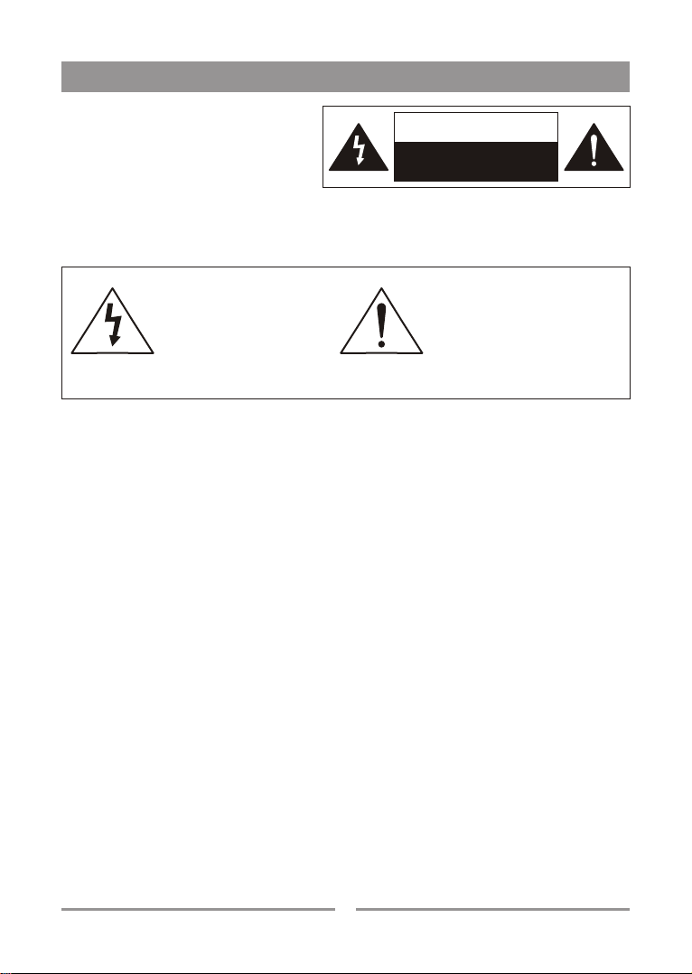
CAUTION
RISK OF ELECTRIC SHOCK
DO NOT OPEN
This symbol, wherever it
appears, alerts you to the
presence of uninsulated
dangerous voltage inside
the enclosure, that may be
sufficient to constitute a
risk of shock.
This symbol, wherever it
appears, alerts you to
important operating and
maintenance instructions in
the accompanying literature.
Read the manual.
2