2. AI008 Controls
1. Input 1 Mixing Row. This row of knobs
controls the amount of signal from the Input
1 jack will be mixed to outputs A-C. A1
controls the amount of Input 1 that appears
at output A. B1 controls the amount of Input 1
that appears at output B. C1 controls the
amount of Input 1 that appears at output C.
2. Input 2 Mixing Row. This row of knobs
controls the amount of signal from the Input
2 jack will be mixed to outputs A-C. A2
controls the amount of Input 2 that appears
at output A. B2 controls the amount of Input 2
that appears at output B. C2 controls the
amount of Input 2 that appears at output C.
3. Input 3 Mixing Row. This row of knobs
controls the amount of signal from the Input
3 jack will be mixed to outputs A-C. A3
controls the amount of Input 3 that appears
at output A. B3 controls the amount of Input 3
that appears at output B. C3 controls the
amount of Input 3 that appears at output C.
4. Input 4 Mixing Row. This row of knobs
controls the amount of signal from the Input
4 jack will be mixed to outputs A-C. A4
controls the amount of Input 4 that appears
at output A. B4 controls the amount of Input
4 that appears at output B. C4 controls the
amount of Input 4 that appears at output C.
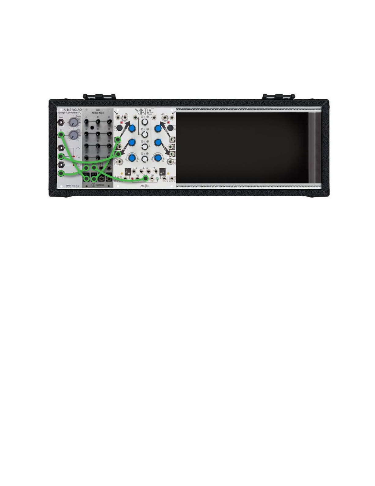
5. Inputs. These are the four inputs of the
Matrix Mixer. The amount of signal passed
from these inputs are controlled by the
Mixing rows.
6. Outputs. These are the separate mix outputs. Each output controls a mix of Inputs 1-4 as defined
by the mixing rows. The A+B+C output is a summed mix of the A, B, and C outputs.
3. Power
The AI008 uses a shrouded header to prevent the cable being plugged in the wrong way. The unit
draws 17mA on the positive and negative side.