Speck XTRAMIX X6 User manual
XTRAMIX X6
40 x 8 x 2 Line Mixer
Installation and Operation
speck electronics
~Please Read Prior To Unpacking~
Instructions

Unpacking & Inspection
The XTRAMIX X6 is shipped in a special protective container and was carefully inspected
both mechanically and electrically before shipment. All items should be physically free of
mars and scratches and in perfect electrical order upon receipt. To confirm this, the mixer
and power supply should be inspected for physical damage that may have occurred in
transit. Any damage should be reported to your dealer or delivery company as soon as
possible.
Unpacking the X6
When you remove your XTRAMIX X6 from the shipping box and remove the foam end caps,
you will see that the mounting brackets are attached to X6 so they extend beyond the front
panel, and turned inward to protect the front panel knobs and buttons during shipping
(See Figure 1).
These brackets are to be removed and will be used for 19” rack mounting or as a desktop
stand. To remove these adapters it is recommended the X6 be set on a flat surface on its
rear connectors (knobs facing up). Remove the 3 Phillips screws on both sides of the mixer.
(See Figure 2). Keep the screws and brackets - you will need them.
It would be a good idea to keep the original packaging. If there is ever the need to send it in
for repair, the original packaging guarantees a safe shipment.
Remove 3
Screws
Figure 1.
Figure 2.

Attaching the mounting brackets for 19” rack mount
The most common use of the mounting brackets is for standard 19” rack mounting. Before
attaching the brackets place the mixer on a flat surface on its rear connectors - knobs facing
up.
Use the (5) black 6-32 Phillips flat head machine screws that have been supplied to attach
each mounting bracket to both sides of the mixer. See Figure 3 for the location of the
mounting holes. Be sure to use all 5 screws on each side.
Attach with
5 Screws
Figure 3.

Attaching the mounting brackets for a desktop stand
The mounting brackets can also be used to place the X6 on a desktop and elevate the mixer
above the desk surface at a 10 degree angle as shown in Figure 4.
First attach the 4 protective rubber bumpers to the front face of the brackets - 2 on each
bracket. (See Figure 5).
To attach the brackets place the mixer on a flat surface on its rear connectors (knobs facing
up). Position the bracket on the side of the mixer so the narrow bracket edge faces inward.
Move the bracket around until the 4 mounting holes align with the threaded holes on the
side of the X6.
(4) Black 6-32 Phillips flat head machine screws are needed to attach the 2 rack adapters to
each side for the location of the mounting holes (See Figure 6). Be sure to use all 4 screws
on each side. Note that these are not the same holes used for the 19” configuration.
Attach Rubber
Bumpers Here
Attach with
4 Screws
Figure 4.
Figure 5. Figure 6.

Proper Ventilation
The X6 will get warm during operation so ventilation holes were placed on the top of the
chassis. These ventilation holes will not be effective if another piece of rack equipment is
placed directly above the X6 blocking the vent holes. It is recommended that you leave a
1U clearance on the top of the X6. If desired, a vented rack panel can installed to cover
blank space in the 19” rack.
We recommend the: Middle Atlantic Products, EVT Series Vent Panel - 1-space
(www.legrandav.com)
For better cooling a 1U quiet cooling fan can be installed above the X6. Reducing heat will
definitely extend the life of the product.
We recommend the: AC Infinity, Model CLOUDPLATE T1-Quiet Rack Cooling Fan System 1U
(www.acinfinity.com)
Note: For ventilation to be effective the fan motors must on the front of the rack chassis to
exhaust air. Ventilation fans that have fan motors on the top of the chassis will not work.
AC Infinity, Model CLOUDPLATE T1
Middle Atlantic Products, EVT Series Vent Panel

Power Supply Installation
One of the primary reasons that the power supply of the XTRAMIX X6 is external is to
insure that the power circuitry enclosed within the power supply chassis maintains a safe
distance from the active electronics of the X6. For that matter, any device that has a strong
magnetic or RF power field should be kept at a reasonable distance from the X6 and its
audio cables.
Because the power supply does not use a cooling fan, it is silent and can be located in the
same room as the mixer. However, it is important that the ventilation holes are not
obstructed and that the unit is operated in free air to prevent overheating. Allow a
minimum of 4” (100mm) of clearance from all ventilation holes.
The Model PS7 external power supply that is included with your mixer is an auto-ranging
supply that can operate with mains voltages of 100 VAC, 120VAC, 220 VAC, 230 VAC, or
240 VAC 50/60 Hz. This power supply does not require a voltage selection switch.
Use only the PS7 external power supply that is supplied with your X6 mixer. Using any
other power supply or power source will most definitely damage the X6.
Your X6 is supplied with a 10’ (3m) gray DC power cable. Before connecting this cable
between the power supply and the X6 make certain the power switch is set to the “OFF”
position. To connect the power supply to the mixer, fit the 10 position connector on the DC
power cable to the chassis mount receptacle on the rear of the X6 labeled “DC POWER
INPUT”. Then fit the 6 position white connector on the DC power cable to the PS7 power
supply connecter labeled “DC OUTPUT”.
The respective connectors are keyed so the plug and the receptacle can fit in only one
direction.

Hooking up the Xtramix X6
A quality installation is essential when wiring any audio system. When the time comes to
actually interconnect your equipment, proceed slowly. Interfacing the many pieces of
electronic equipment to your mixer and audio system should be a logical, methodical
process.
Start by connecting only the monitor power amp (or powered speakers) to the Xtramix X6,
and then add one line signal to the mixer at a time; carefully listening and monitoring your
progress. If a problem arises, such as a buzz, hum, intermittent signal, or nonexistent
signal, stop at that point and solve the problem before proceeding.
Due to the high performance of the Xtramix X6, it is recommended that you use only the
highest quality audio cable. A high quality cable by definition is a cable that provides good
mechanical strength, high microphonic noise immunity, high frequency response, low
crosstalk, and 100% shielding ability. All audio cable used with the X6 should be a 3
conductor foil shield type (2 inner conductors and a shield drain conductor). It is not
recommended that the 2 conductor "off the shelf cables" be used.
All wire and cable interfaced to the X6 should be terminated with high quality connectors.
A ¼" plug or XL connector should make a positive connection to its respective mating jack
and provide adequate strain relief to its cable. All connectors should also have a metal shell
to provide 100% shield for exposed conductors.
We do believe that “you get what you pay for” and advise not to purchase lower quality
cables. We recommend that you purchase from a reputable cable manufacturer that uses
brand name materials. Brand name cables include (in no particular order) Mogami, Canare,
Belden, Gepco, Redco, and ProCo. Connector brands include Switchcraft and Neutrik.

Radio Frequency Interference and Electro Magnetic Interference
Any device that emits a high EMI (Electro Magnetic Interference) or RFI (Radio Frequency
Interference) energy field should be treated with suspicion. EMI is considered any
unwanted signal which adversely affects the operation of the XTRAMIX X6 or the audio
system.
Stated simply, the undesirable effects of EMI may be perceived as a low frequency smooth
sounding 60Hz hum; a low frequency "edgy" sounding 120Hz buzz; or a higher frequency
"whine" caused by the timing circuits in microprocessor based devices.
Almost every electronic device generates some amount of EMI emissions. These emissions
can be transmitted as electromagnetic radiation or simply conducted though audio cables
and power cords. In the same respect, most electronic devices are also very susceptible to
the EMI emissions generated by other electronic devices.
There are natural and man made sources of EMI that you can't do anything about. These
sources include radio, TV, and radar transmitters, as well as motors, lights, and computers.
Even the Sun and atmospheric conditions can be contributors to noise that you experience
in your audio system.
There are generally 3 elements that must be present for EMI to exist. These include the
source of the EMI (conducted or radiated), the propagation medium by which EMI is
transmitted (directly on the cables or through the air), and the receptor that suffers the
adverse affects of EMI. If any of these 3 elements are eliminated or reduced, the EMI
interference will be eliminated or reduced.
Physical Placement of Adjacent Equipment
The more electronic equipment operating within a studio or equipment rack, the higher the
EMI emissions. The more audio cable and low level audio equipment that exists within the
same proximity, the greater possibility of unwanted noise. The result of EMI in an audio
system manifests itself as a buzz, hum, whine, or all three.
The occurrence of EMI and RFI in a contemporary studio system should be of great concern
and not overlooked when installing the Xtramix X6. Electronic equipment such as power
amplifiers, power supplies (especially wall mount type), video monitors, computers, certain
synths and samplers must be located away from the X6 and its associated cables. It may be
necessary to alter the positions of certain equipment that you feel would cause buzzes or
hums in the mixer system.

Overview
We hope to give you basic information on the operation of the Xtramix X6 (X6) and adequately
describe its controls, switches, and connectors.
The information is intended to help with the technical process when using your X6. Words alone
could not adequately describe how to adjust the controls for every situation you might encounter
with the X6. You should experiment with settings and routing techniques to achieve the best
results for any particular situation. Your ears should be your best gauge of how to adjust the
settings on the X6 to make the sound fit your requirements.
Default Control Settings
Before any attempt is made to operate the X6, it would be a good idea to set all controls to their
neutral positions. This gives you a reference point to work from when adjusting controls and
switches.
All volume controls, including aux sends, aux returns, and master level controls should be set to
their full counter-clockwise setting. All pan controls should be set centered. The exception to this
is the rear panel Solo Trim that has been factory calibrated and does not need adjustment.
All pushbutton switches on the front panel and gain switches on the rear panel should be set to
the out position.
When any future reference is made to the controls or switches on the X6, it will be assumed that
they have been set to their neutral positions.
Operation
INPUT CHANNEL
Each input channel has a stereo level control, pan/balance,
8 group assign, and Stereo Mix assign. 4 aux sends (2
variable sends selectable from 4 aux busses), Aux pre/post
select, stereo aux select for true stereo effects send, In-
place Solo, and presence of signal LED. The rear panel of
the X6 includes left and right active-balanced ¼” TRS
inputs with gain select, and active-balanced left & right
direct outputs on ¼” TRS jacks. The stereo direct outs are
factory configured to follow the level and pan control, but
may set to pre-pan. Together with the 8 groups, the
pannable stereo directs give the X6 a lot of recording
power.
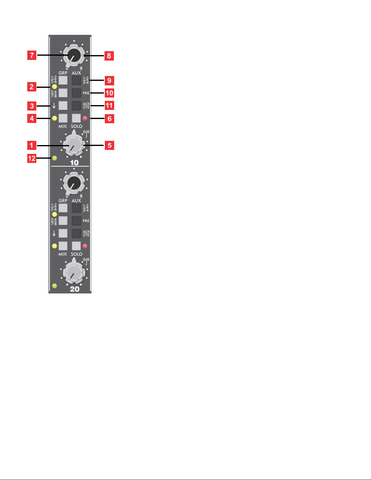
1. Stereo Level Control - This small inner knob is a dual
rotary potentiometer that simultaneously and equally
adjusts both the left and right input channel levels.
The 0dB mark on the level control is the "unity gain"
setting. There is 12dB more gain available past the "0dB"
mark.
2. Group Assign - The two assign pushbutton switches, in
conjunction with the Pan/Balance Control, allows an input
channel to be assigned to any 4 subgroup pairs. A yellow
LED on this switch illuminates if either group assign switch
is pressed.
3. Assign Changeover Switch - In the up position, the two group Assign Switches [#2] will
select groups 1-2 and 3-4. When pressed, the two group Assign Switches will select groups
5-6 and 7-8.
4. Mix Assign - The Mix Assign switch, in conjunction with the Pan/Balance control, allows
an input channel to be mixed to the main left/right output. A yellow LED on this switch
illuminates indicating that the Mix Assign has been enabled.
5. Pan/Balance Control -The larger outer knob, in conjunction with the group assign
switches and mix assign switch, allows the input channel to be assigned to any the 4 sub-
group pairs or stereo mix respectively. When a stereo source is connected to an input
channel, this control acts as a left/right “balance” control. If a mono signal is plugged into
the Left (mono) input jack, then this control acts as a traditional assign “pan” for the
selected group assign switch and mix assign.

6. In-Place Solo Switch - In-Place soloing allows you to isolate the stereo input channel
while maintaining its stereo perspective. The source of the solo signal is post (after) the
channel's level and pan controls. When a solo switch is pressed, any adjustment to the
channel’s level control will be evident in the monitor and headphone playback. A red LED
illuminates any time its associated Solo Switch is pressed.
7. Aux Send (Odd) - The smaller inner knob adjusts the level for the selected "odd" aux
busses 1 or 3 when selected with the Aux Assign switch [#9].
8. Aux Send (Even) - The larger outer adjusts the level for the selected "even" aux busses 2
or 4 when selected with the even aux assign Switch [#9].
9. Aux Assign Switch - When this switch is in the up position, Aux Send (Odd) [#7] sends to
aux 1 and Aux Send (Even) [#8] sends to aux 2. When this switch is pressed, Aux Send (Odd)
sends to aux 3 and Aux Send (Even) sends to aux 4.
10. Aux Pre - This switch selects the source of the Aux Sends. In the up position, the aux
sends reflect any adjustment after (Post) the level control. When this switch is pressed (Pre)
the input level control has no effect on the level set at the Aux Sends.
11. Stereo Aux Select - Each input channel incorporates an “Aux Ste” switch. When this
switch is in the up position, the source for the aux sends is the sum of the left and right
input signals, post the input level control. When the “Aux Ste” switch is in the down
position, the source for aux sends 1 and 3 is the left input signal, and the source for aux
sends 2 and 4 is the right input signal.
12. Presence of Signal - This LED will illuminate when a signal is present at the left or right
channel. This provides for easy identification of an active signal even when a channel is
unassigned and sound is inaudible.
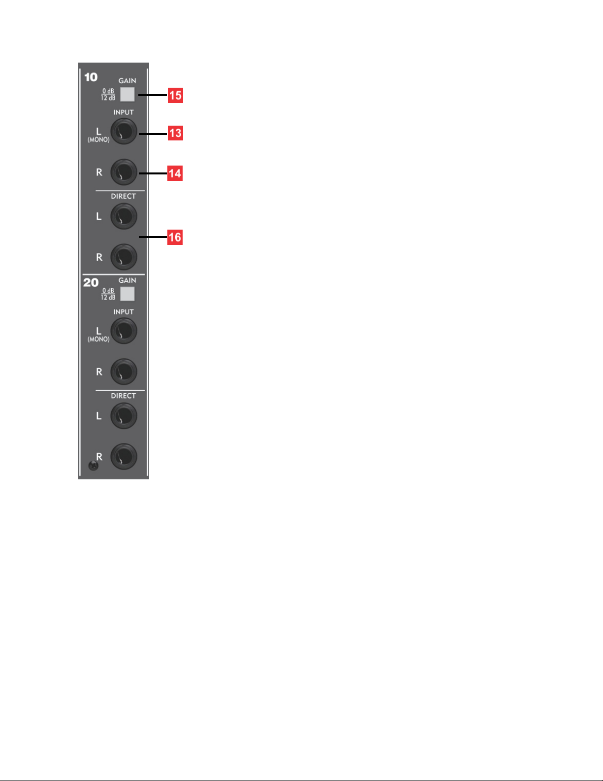
13. Line Input Left (Mono) - This input is used to connect
the left side of a stereo or dual channel source. The (mono)
designation on this jack indicates that this jack should be
used when you have a monaural source.
14. Line Input Right - This input is utilized to connect the
right side of a stereo or dual channel source. A “stereo”
input channel will only function when both the left and
right inputs are connected.
The stereo input channels of the X6 will work with either
balanced tip-ring-sleeve (TRS) ¼" plugs or unbalanced tip-
sleeve (TS) ¼" plugs.
15. Gain Select - To optimize the wide range of audio signals
that will normally be interfaced to the Xtramix, each X6
input channel has two gain settings available: 0dB and
12dB. The “0dB” setting is intended for professional audio
equipment that operates at a +4dBu or -18dBFS, and the
“12dB” setting would be for many synth/samplers, or
unbalanced gear that has lower output signal level.
16. Pannable Stereo Direct Outputs - The standard X6 is
configured with left and right pannable direct outputs. The
X6 may be ordered with direct outputs configured “pre” the
pan pot for customers that do not need pannable direct.
The Direct Outputs provide a balanced line level signal from
the channel and operate at a nominal level of +4dBu.
Together with the 8 groups, the pannable stereo directs
give the X6 a lot of recording power.
AUX RETURN SECTION
Each stereo aux return has stereo level and pan, 8 group
assign, mix assign, and In-place solo, and has active-balanced
left and right ¼” TRS balanced inputs.
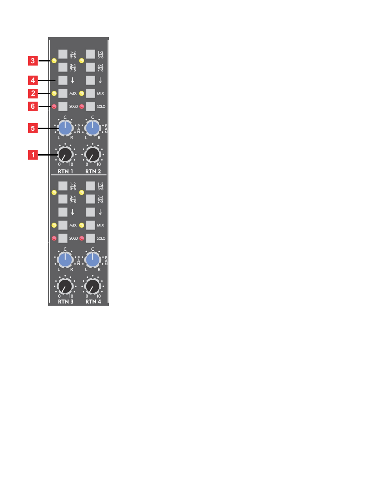
1. Stereo Aux Return Level - This control is a dual rotary
potentiometer that simultaneously and equally adjusts both
the left and right channel levels. A return level setting of
approximately two to three o'clock will yield an adequate
level when matched with an effects unit that is properly
operated at a professional input/output level of +4dBu.
2. Mix Assign - The Mix Assign switch, in conjunction with
the Pan/Balance control, allows an aux return channel to be
mixed to the left/right main output. A yellow LED on this
switch illuminates indicating that the Mix Assign has been
enabled.
3. Group Assign - The two assign pushbutton switches, in
conjunction with the Pan/Balance Control, allows an aux
return to be assigned to any 4 subgroup pairs. A yellow LED
on this switch illuminates if either group assign switch is
pressed.
4. Assign Changeover Switch - In the up position, the two
group Assign Switches [#3] will select groups 1-2 and 3-4.
When pressed, the two group Assign Switches will select
groups 5-6 and 7-8.
5. Pan/Balance Control - This knob in conjunction with the group assign switches and mix
assign switch, allows the aux return channel to be assigned to any of the 4 sub-group pairs
or stereo mix respectively. When a stereo source is connected to an aux return channel, this
control acts as a left/right "balance" control. If a mono signal is plugged into the Left
(mono) input jack, then this control acts as a traditional assign "pan" for the selected group
assign switch and mix assign.
6. In-Place Solo Switch - In-Place soloing allows you to isolate the stereo aux return while
maintaining its stereo perspective. The source of the solo signal is post (after) the channel's
level and pan controls. When a solo switch is pressed, any adjustment to the channel's level
control will be evident in the monitor and headphone playback. A red LED illuminates any
time its associated Solo Switch is depressed.
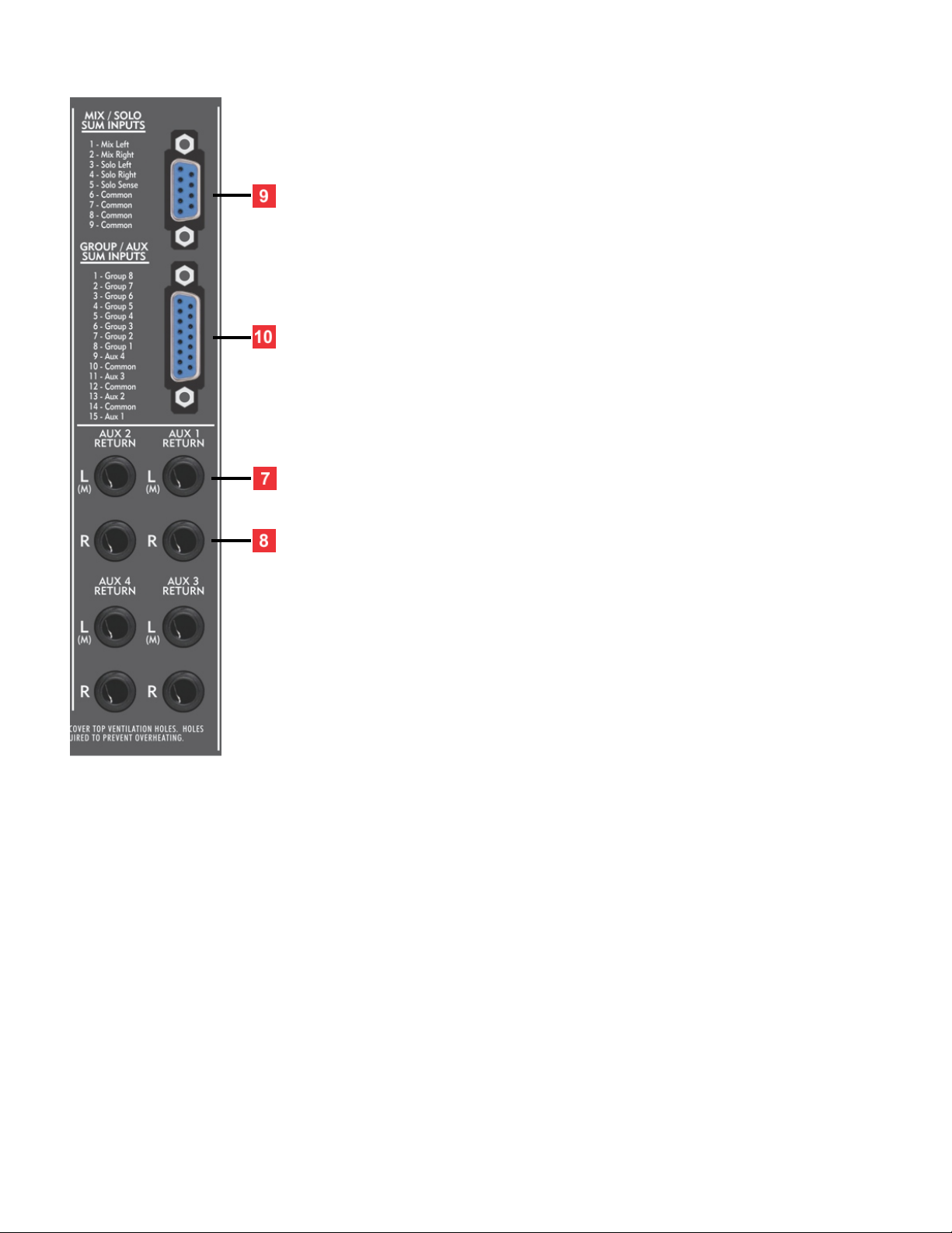
7. Line Input Left (Mono) - Typically, this input is used to
connect the left side of a stereo or dual channel source. The
(M) designation on this jack indicates that this jack should be
used when you have a monaural source.
8. Line Input Right - Typically, this input is utilized to connect
the right side of a stereo or dual channel source. A "stereo"
input channel will only function when both the left and right
inputs are connected.
The stereo aux return channels of the X6 will work with
either balanced tip-ring-sleeve (TRS) ¼" plugs or unbalanced
tip-sleeve (TS) ¼" plugs.
9. Mix and Solo summing - This DB9 connector provides a
convenient way to receive external line level signals directly
into the X6 mix and solo busses. This interface can be used as
an expander input for a Speck X.Sum mixer, or any audio
product with line level outputs.
10. Group and Aux summing inputs - This DB15 connector
provides a convenient way to receive external line level
signals directly into the X6 group and aux busses.
GROUP AND AUX MASTERS
Each group master has level control, pan, a stereo
mix assign, in-place solo, and insert select switch.
There are 4 aux master levels with solo. Each of
the 8 group channels has active-balance ¼" TRS
output jacks that are referenced to +4dBu,
balanced ¼" send/receive insert jacks, and 4
active-balanced aux master output jacks.
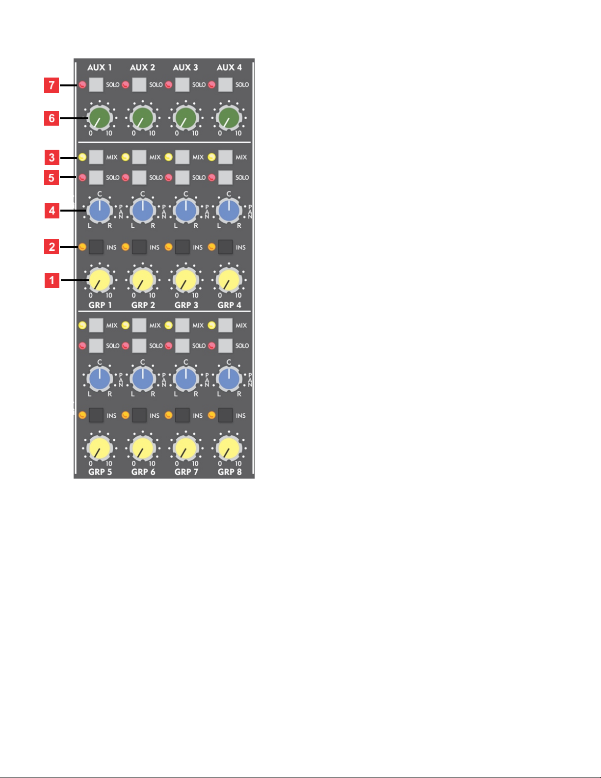
1. Group Master Level - This control adjusts the
level for each of the 8 sub-groups. Each section
includes a Group Master level that controls a
balanced ¼" balanced TRS output on the rear
panel. Metering for the group outputs is provided
by two LED VU meters in selectable pairs (1/2,
3/4, 5/6, 7/8).
2. Insert Switch - Each group channel on the X6
has a balanced send and return available via
separate ¼" TRS jacks on the rear connector
panel. The insert signal path is immediately after
the group active combine circuitry and just before
the group master level. When this insert switch is
pressed, any audio device connected to the insert
connectors is inserted in the group master audio
path. An orange LED on this switch illuminates
indicating that the insert is enabled.
3. Mix Assign - The Mix Assign switch, in conjunction with the Pan control, allows a group
master to be mixed to the left/right main output. A yellow LED on this switch illuminates
indicating that the Mix Assign has been enabled.
4. Pan - This center detent Pan control places the group master anywhere in the stereo
left/right mix when the Mix switch is enabled.
5. In-Place Solo Switch - In-Place soloing allows you to isolate any group channel while
maintaining its stereo perspective. The source of the solo signal is post (after) the group's
level and pan control. When a solo switch is pressed, any adjustment to the group’s level
control will be evident in the monitor and headphone playback. A red LED illuminates any
time its associated Solo Switch is pressed.
6. Aux Send Master - The 4 Aux Masters provide master level control to the balanced aux
send outputs on the rear panel. When matched with an effects unit that is properly
operated at a professional input level of +4 dBu, the optimum setting for this pot is typically
anywhere from 2 to 3 o'clock.
7. Solo - When a solo switch is pressed, any adjustment to the Aux Master level control will
be evident in the monitor and headphone playback. A red LED illuminates any time its
associated Solo Switch is enabled.
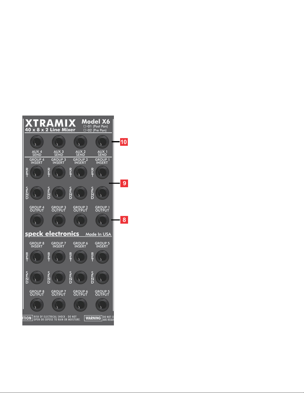
8. Group Outputs - These balanced ¼” TRS jacks
are the outputs for groups 1 through 8. The
signal present at these jacks is adjusted with the
group master level control [#1] on the front
panel.
9. Insert Send/Return - Each group channel has
balanced ¼" TRS send and return insert jacks
and is active when the insert switch [#2] on the
front panel is enabled. The insert jacks provide
line level inter-stage access to the group (pre)
the Group Master level control. This means that
any device interfaced to these jacks will not be
affected by any adjustments of the Group
Master.
The insert jacks may be utilized to connect
processors such as limiters, equalizers, or a
color/character module.
10. Aux Send Outputs - Each of the 4 aux send
channels have a balanced ¼" TRS jack to
interface to the input of an effects processor.

MASTER SECTION
The master section includes a stereo master level,
insert switch, a control room monitor master with A/B
speaker output select, and headphone level control.
The monitor section also has 2 two track returns with
level control. The rear panel has a full complement of
active-balance ¼" TRS output jacks; for the left and
right mix, send/receive insert jacks, monitor outputs,
and 2 track returns.
1. Stereo Master - This control acts as the master
volume to the stereo mix output. The operation of the
Mix Master control does not affect the Monitor or
Headphone level. If required, the Xtramix may be
configured (on side panel) so the source of the Monitor
and Headphone is after (post) the Mix Master Level
control.
2. Insert Switch - The master mix section has left and
right balanced insert connectors. When this switch is
pressed, any dual channel audio device connected to
the insert connectors is inserted in the channel's audio
path. An orange LED on this switch illuminates
indicating that the insert is enabled.
3. Dual VU Displays - These 10 segment VU (volume units) meters indicate the relative
levels of the stereo program and 8 group outputs, and are sensitive from -20dB to +3dB.
A meter reading of zero VU reflects a mixer output level of +4dBu, the industry professional
standard. This VU meter circuit was designed to approximate the ballistics of a "taut band"
analog style VU meter. The mix and group outputs have a maximum output level of +27dBu.
4. VU Meter Select - This momentary switch selects the VU meters for the 8 group outputs
and the stereo mix master. To select a pair of meters, press this switch until the desired pair
is indicated on the lower LED's: L-R, 1-2, 3-4, 5-6, or 7-8.
5. Monitor Master -This controls overall level to both the A or B stereo monitor outputs and
operates independent of the Mix Master and Headphone Master. Typically, the monitor
outputs would be connected to a stereo power amplifier for purposes of driving a personal
monitoring system. If required, the Xtramix may be configured (on side panel) so the source
of the Monitor and Headphone is after (post) the stereo Master Level Control.

6. Monitor A-B Select - This switch selects either the Monitor-A or Monitor-B outputs
7. Monitor Mute -This switch mutes the master monitor output without affecting the mix
and headphone outputs. When pressed, the LED directly below will illuminate, indicating
the monitor signal has been muted.
8. Stereo Headphone Master -This controls the volume of the stereo headphone circuit and
operates independent of the mix master and monitor master. If required, the X6 may be
configured (on side panel) so the source of the monitor and headphone is after (post) the
Mix Master level control.
9. Headphone Jack - This standard ¼" TRS stereo phone jack will accommodate most
popular stereo headphones.
10. Mono Select - When pressed, this switch sums the left and right signal together,
creating a mono composite to the monitor and headphone mix. The operation of the mono
switch does not affect the main stereo mix
11. 2 Track Returns #1 and #2 - These stereo controls adjust the level of a external stereo
source connected to the 2T returns on the rear panel and can be mixed and blended with
the monitor and headphone outputs. This could be a CD player or stereo DAW audio signal.
This stereo signal is not mixed to the stereo mix or 8 groups. Each has an "On" pushbutton
to enable the returns.
12. Power/Solo LED - This LED indicates the operational status of the Xtramix. This dual
color LED will change from green to red, as a master solo indicator when any solo switch is
pressed.

13. Mix Outputs - These balanced ¼" TRS jacks are the
left and right outputs for the stereo master. The signal
present at these jacks is adjusted with Mix Master
level [#1] on the front panel.
14. Mix insert send/return - The mix master has left
and right balanced ¼" TRS send and return insert jacks
and are active when the insert switch [#2] on the front
panel is enabled. The insert jack provides line level
inter-stage access to the mix bus before (pre) the Mix
Master level control. This means that any device
interfaced to these jacks will not be affected by any
adjustments of the Mix Master control.
15. Monitor outputs A and B - These balanced ¼" TRS
jacks are available for hooking up a power amp or
power speakers. The signal present at these jacks is
adjusted with the Monitor Master control [#5] and
selected with the monitor A-B select [#6] on the front
panel.
16. 2 track returns #1 and #2 - These balanced ¼" TRS
jacks allow interface of external auxiliary stereo line
level signals. The (M) designation on this jack indicates
that this jack should be used when you have a
monaural source. These inputs are adjusted with the
2 TRK level controls [#11] on the front panel.
17. Solo trim control - This control adjusts the overall stereo in-place solo listening level to
the monitor and headphone outputs. The adjustment of this control permits the volume of
the soloed signal to match the level of the normal stereo mix.
The rear panel Solo Trim has been factory calibrated and does not need adjustment.
18. DC power inlet - This connector is used to connect the DC cable from the external
power supply.
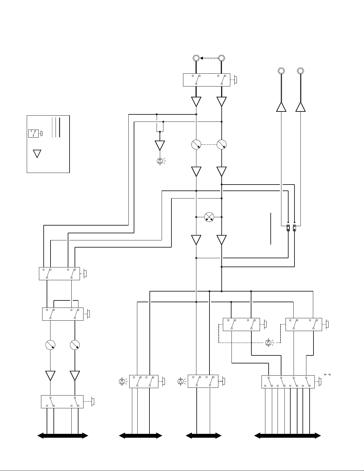
AUX BUS
DIRECT OUT
CONFIGURATION
MIX
POST PAN
PRE PAN
SOLO
CHANGEOVER
1 TO 4
5 TO 8
GROUP
1-2 / 5-6
GROUP
3-4 / 7-8
AUX
1-2 / 3-4
ODD
AUX SEND
EVEN
AUX SEND
SOLO BUS MIX BUS GROUP BUS
G1
G5
G2
G6
G3
G7
G4
G8
L
R
SL
SR
SS
A1
A3
A2
A4
LEFT
RIGHT
DIRECT OUTS
LEFT
RIGHT
LINE INPUTS
PRESENSE
OF SIGNAL
GAIN SELECT
0dB / 12dB
LEVEL
PAN
AUX
MONO / STEREO
POST / PRE
Xtramix X6
LEGEND
SWITCH LINE AMP
BALANCED SIGNAL
UNBALANCED SIGNAL
LOGIC CONTROL SIGNAL
Input Channel Signal Flow
Copyright © 2021 by Speck Electronics
Table of contents
Other Speck Music Mixer manuals


