AIC TEXAS 99 Manual

EN
installation
and maintenance
manual
FOR THE INSTALLER AND THE USER
99 · 230 kW
FLOOR — STANDING CONDENSING STORAGE WATER HEATER
H-093630 • 00
TEXAS

G-2 H-093630_EN • 00
Table of ConTenTs
General InformatIon ...................................... G-3
Liabilities of the Manufacturer, the Installer and the
End user....................................................................G-3
About this Manual.....................................................G-4
Appliance Naming.....................................................G-5
Appliance Marking ....................................................G-5
Safety Instructions ....................................................G-6
Package Contents ...................................................G-7
Product descrIPtIon ..................................... G-8
TEXAS 99 - 230.........................................................G-8
General Description............................................................ G-8
Frost Protection.................................................................. G-8
Safety Devices ................................................................... G-8
Optional equipment............................................................ G-8
Control Panel and Main Functions..........................G-12
Symbols and Messages on the Control Panel .......G-13
technIcal sPecIfIcatIons .............................. G-14
Dimensions ............................................................G-14
Clearances ..............................................................G-15
Performance and Eciency Data ...........................G-16
ErP Data..................................................................G-16
Electrical Data.........................................................G-16
Hydraulic Data ........................................................G-16
Combustion Data....................................................G-17
Gas Data .................................................................G-18
InstructIons for the user............................ u-19
Safety Instructions for the User ..............................U-19
Disposal of the Product at the End of Service Life .U-20
Periodic checks .....................................................U-20
Starting the Appliance ............................................U-21
Stopping the Appliance ..........................................U-21
What to Do if... ........................................................ U-21
Operating the Controller - End User Level..............U-22
Basic Settings .........................................................U-24
Product InstallatIon ................................... u-26
Safety Instructions for the Installation ....................U-26
Unpacking the Product.............................................I-27
Handling the Product................................................I-27
Installing and Preparing the Appliance .....................I-28
Opening and Closing the Front Door and Access Panels . I-29
Inverting the Opening Side of the Front Door...........I-30
Requirements for the Hydraulic Circuits ...................I-31
Safety Instructions for the DHW Circuit....................I-34
Typical Hydraulic Connections - DHW Circuit ..........I-35
Safety Instructions for the Chimney Connections ....I-36
Chimney Connection ................................................I-38
Engineering the Chimney System.............................I-41
Accessories...............................................................I-41
Safety Instructions for the Gas Connection..............I-42
Gas Conversion ........................................................I-43
Preparing the Appliance for Gas Conversion ...................... I-44
Adjustment of Fan Speeds ................................................. I-45
Combustion Adjustment for Gas Conversion ....................... I-46
Safety Instructions for the Electrical
Connections..............................................................I-48
Cables.......................................................................I-48
Routing the Cables ...................................................I-48
Accessing the Electronic Board and Low and High
Voltage Terminal strips..............................................I-49
Wiring Diagram - TEXAS 99......................................I-50
Wiring Diagram - TEXAS 230....................................I-52
commIssIonInG ...............................................I-54
Safety Instructions Before Start-up ..........................I-54
Filling the Water Heater.............................................I-54
Start-up and Commissioning....................................I-55
Combustion Adjustment ...........................................I-55
Commissioning Wizard .............................................I-56
General Structure of the Commissioning Wizard................. I-57
maIntenance..................................................I-60
Safety Instructions for Maintenance .........................I-60
Maintenance Requirements ......................................I-61
Shutting Down for Maintenance ...............................I-62
Draining the Circuit ...................................................I-62
Restarting after Maintenance....................................I-62
Checking the Flue Gas (FPS) and Air (APS) Pressure
Switches operation ...................................................I-63
Removing, Cleaning and Installing the Condensate Trap ... I-64
Removing and Installing the Ignition and Ionisation
Electrodes .................................................................I-66
Removing and Installing the Fan, Venturi and Gas
Valve (TEXAS 99).......................................................I-68
Removing and Installing the Fan, Venturi and Gas
Valve Assembly (TEXAS 230) ....................................I-70
Removing and Installing the Burner..........................I-72
Removing and Installing the Burner Plate.................I-74
Checking and Cleaning the Combustion Chamber ..I-76
Checking the Scaling in the Appliance and Descaling I-77
Appliance Settings for the Installer ...........................I-78
Access Levels .................................................................... I-78
Menus and Settings ........................................................... I-78
Structure of Menus for the Installer ..........................I-79
Error Codes and Solutions........................................I-81
Troubleshooting ........................................................I-84
Maintenance Messages ............................................I-85
Installation Checklist .................................................I-86
Combustion Parameters - Log Sheet .......................I-89
Water Parameters - Log Sheet .................................I-90
declaratIon of conformIty ............................I-91
INDEX OF ILLUSTRATIONS
Fig. 1. Data Plate - Typical .............................................................. G-5
Fig. 2. TEXAS Water Heater Packaged for Transport.................... G-7
Fig. 3. TEXAS 99 - 230 Components - Front views ...................... G-9
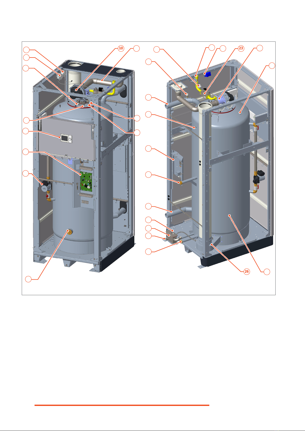
Fig. 4. TEXAS 99 - Inner Components - Front & rear views........ G-10
Fig. 5. TEXAS 230 - Inner Components - Front & rear views ..... G-11
Fig. 6. Control Panel...................................................................... G-12
Fig. 7. Typical Display.................................................................... G-13
Fig. 8. Single Appliance Clearances - View from the Top ........... G-15
Fig. 9. Appliance Transport and Installation................................... I-27
Fig. 10. Installing the Air Inlet Silencer........................................................... I-28
Fig. 11. Opening and Closing the Access Door and Panels........... I-29
Fig. 12. Inverting the Door Opening Side......................................... I-30
Fig. 13. Typical DHW Circuit ............................................................. I-35
Fig. 14. TEXAS 99 Gas Valve ........................................................... I-42
Fig. 15. TEXAS 230 Gas Valve......................................................... I-42
Fig. 16. TEXAS 99 - Shutter Pre-adjustment for Propane............... I-44
Fig. 17. TEXAS 230 - Shutter Pre-adjustment for Propane ............ I-44
Fig. 18. Fan Speed Adjustment - Typical Screen ............................ I-45
Fig. 19. Combustion Adjustment - Control Panel............................ I-46
Fig. 20. Combustion Adjustment on Gas Valves ............................. I-47
Fig. 21. Routing the Electrical Cables .............................................. I-48
Fig. 22. Accessing the Electronic Board and High & Low voltage
Terminal Strips...................................................................... I-49
Fig. 23. Filling the Water Heater - Typical......................................... I-54
Fig. 24. Combustion Adjustment on Gas Valves ............................. I-55
Fig. 25. Draining the Appliance - Typical.......................................... I-62
Fig. 26. Testing the Air Pressure Switch and Flue Pressure SwitchI-63
Fig. 27. Cleaning the Condensate Pipe and Trap............................ I-65
Fig. 28. Removing and Installing the Electrodes ............................. I-67
Fig. 29. TEXAS 99 - Removing and Installing the Fan/Venturi
Assembly and Gas Valve ..................................................... I-69
Fig. 30. TEXAS 230 - Removing and Installing the Fan/venturi/
Gas Valve Assembly............................................................. I-71
Fig. 31. Removing and Installing the Burner.................................... I-73
Fig. 32. Removing the Burner Plate.................................................. I-75
Fig. 33. Cleaning the Combustion Chamber ................................... I-76
Fig. 34. Descaling the Water Heater................................................. I-77

Manufacturer
Our products are manufactured in compliance
with the requirements of the applicable Europe-
an Directives and standards, and are therefore
delivered with all the required documentation
and markings.
The quality of our products is essential to
us, and we aim therefore at improving them
continually. To this end, we reserve the right
to change the technical characteristics and
features of our products without prior notice.
Please check for the latest revision of the man-
ual on our website (www.myaic.eu).
The manufacturer shall not be held liable for
any malfunction of the product resulting from:
îThe failure to comply with the safety
and installation instructions provided
herein,
îThe failure to comply with the safety
and operation instructions and recom-
mendations provided herein,
îThe failure to have the appliance main-
tained regularly,
îA modi cation of the appliance that is
not approved by the manufacturer,
îThe use the product for any other pur-
pose than its intended use,
îThe use of components and accesso-
ries that are not approved by the man-
ufacturer.
Installer
The installer is responsible for the correct in-
stallation, conversion (as required) and com-
missioning of the appliance according to:
îThe instructions and recommendations
provided herein
îThe applicable regulations and standards
The installer shall provide the end-user with:
îAny relevant explanation about the op-
eration of the appliance and the heat-
ing system as well as the safety devices
that are provided,
îAny instruction regarding periodic
checks to be performed and possible
anomaly to be reported
îAll the documentation delivered with
the appliance and installed accessories.
The installer shall also inform the end-user of
the necessity to have the appliance checked
and maintained regularly by a quali ed profes-
sional.
End-user
To ensure the best performances and safety of
the appliance, the end-user shall:
îMake sure that the appliance is in-
stalled, converted (as required), com-
missioned and adjusted by a quali ed
professional,
îMake sure that the appliance is checked
and maintained regularly by a quali ed
professional,
îComply with all the instructions and rec-
ommendations provided in the appliance
documentation,
îMake sure to receive from the installer
all the necessary explanations related
to the operation of the appliance and
the safety devices,
îMake sure to receive from the installer
all the appliance and accessories doc-
umentation,
îKeep all the appliance documentation
in a safe place for future use.
The end-user shall use the product for its in-
tended use.
îShould the installer or the end user not comply with the instructions and require-
ments stated in this manual, the warranty will be void.
îFor more information on the warranty terms and conditions, please connect to
our website: www.myaic.eu.
i
G-3
H-093630_EN • 00
General InformatIon
Liabilities of the Manufacturer, the Installer
and the End user

This documentation is part of the product. It will be handed over to the end-user who will keep it,
with all the other applicable documents, in a safe place and readily available for use.
Before installing, operating or maintaining the appliance, please carefully read this manual and all
the applicable documents provided with the components and accessories. They contain essen-
tial safety information.
Symbols in this Manual Symbols on the Appliance
Symbols on the Packaging
Indicates an essential instruction
which, if not followed, can result
in a hazardous situation that can
cause serious damage to equip-
ment and/or injuries or death.
Indicates an important instruction
which, if not followed, could re-
sult in a hazardous situation that
could cause damage to equip-
ment and/or injuries.
Indicates an essential instruction
in relation with the presence of
electrical power and a danger of
electrical shock.
The appliance must be started/
stopped using the ON/OFF switch
installed on the appliance.
ON OFF
The electrical supply to the appli-
ance must be activated/deactivated
through the external circuit breaker
or the power supply cable must be
connected/disconnected.
The gas supply to the appliance must
be provided/shut down through the
external gas tap.
The water circuit of the appliance
must be full of water/empty.
The access panel(s) of the appliance
must be open/closed.
This side up
Keep dry
Fragile
Do not stack
The appliance must have cooled down.
Indicates important information.
i
Gas connection.
Ground / Earth.
High Voltage - danger of electric shock.
Gas connection.
Domestic hot water outlet.
Cold water inlet.
Cold water inlet connection.
DHW connection.
DHW recirculation connection.
G-4 H-093630_EN • 00
General InformatIon
About this Manual
For an explanation of the symbols on the control
panel, please see “Symbols and Messages on
the Control Panel” on page G-13.
The prexes used in the page numbering
indicate the following:
G- : General information
U- : Pages intended for the end user
I- : Pages intended exclusively for the
qualied professional (e.g. installer)
i

Fig. 1. Data Plate - Typical
Texas
Floor-Standing Condensing Storage Water Heater | Stojący kondensacyjny pojemnościowy podgrzewacz c.w.u |
Productor de ACS en condensación con acumulación | Produttore di acqua calda sanitaria a condensazione con
accumulo integrato | Vloer-staande condenserende waterverwarmingstoestel | Akumulacijski talni kondenzacijski
grelnik vode | Bodenstehender Kondens-Wassererboiler | Chauffe-eau sol à condensation et accumulation | Produtor
de AQS em condensação com acumulação | Напольный конденсационный накопительный водонагреватель |
Akumulacioni podni kondenzacijski grijač vode | Επιδαπέδιος Ταχυθερμαντήρας Ζεστού Νερού Χρήσης Τεχνολογίας
Συμπύκνωσης |Газов подов Кондензен обемен Бойлер | Preparator apa calda menajera de sol,
cu arzator pe gaz in condensatie
Model
PIN
Serial No.
Date
AIC Europe No.
AIC Europe B.V.
Graafschap Hornelaan 163A
NL-6001 AC Weert
The Netherlands
1015 20
G20 – 20 mbar
Adjusted | Skorygowana | Configurado | Regolato | Afgesteld op | Prilagojen | Eingestellt für | Réglé pour | Configurado |
Скорректировано | Podešen | Προσαρμοσμένη | Коригирано | Ajustat
G20 G25 G31
Q
kW
P
kW
EXAMPLE
G-5
H-093630_EN • 00
General InformatIon
Appliance Marking
The data plate is located at the back of the appli-
ance.
Appliance Naming
In the documentation, products of the Texas
oor-standing (FS) range can be designated indif-
ferently using their full name or abbreviated name:
Texas 99 or TX 99 FS
Texas 230 or TX 230 FS
Symbol Description
Electrical data
PMS maximum operating
pressure
Tmax maximum primary
temperature
Vwater content
PMS maximum operating
pressure (DHW circuit)
Tmax maximum DHW
temperature
Vwater content
Chimney types
NOx class
The use of symbols on the data plate depends on the type of product.
i
Symbol Description
Qmin Minimum heat input
Qn Nominal heat input
Pmin (80/60°C) Minimum heat output (80/60°C)
Pn (80/60°C) Nominal heat output (80/60°C)
Pmin (50/30°C) Minimum heat output (50/30°C)
Pn (50/30°C) Nominal heat output (50/30°C)
CE sign for the compliance of the
device with CE directives
EAC sign for the compliance of the
device with all technical regulations
of the Eurasian Customs Union
Note about handling waste
electronic equipment

IF YOU SMELL GAS:
→DO NOT:
îUse an open ame
îSmoke
îUse electrical devices (phones,
doorbell, etc.) or switches
→DO:
îClose the gas supply
îOpen all doors and windows to
ventilate the room
îInform the neighbours of the danger
by knocking at the doors.
îGet out of the building
îCall the gas company
îThis product is intended for the pro-
duction and storage of Domestic Hot
Water.
îThis appliance must be installed ac-
cording to the applicable local regu-
lations and standards.
îThis appliance can be used by children
who are at least 8 years old and by per-
sons with reduced physical, sensory or
mental capabilities or lack of experience
and knowledge, provided that they are
under supervision or have been given
instructions concerning the use of the
appliance in a safe way and that they
understand the hazards involved.
îCleaning and user maintenance shall
not be performed by children without
supervision. Children shall not play
with the appliance.
îAny modi cation to the appliance
and its components is strictly forbid-
den without the prior written consent
of the manufacturer.
îIf components need to be replaced,
only genuine factory parts or compo-
nents approved by the manufacturer
must be used.
îWhen working on the appli-
ance and the system, make
sure to use the appropriate
tools to avoid damaging the
pipes and components.
îIf works need to be performed close to
the appliance (e.g. in the boiler room
or close to the air inlets), make sure
to shut down the appliance to prevent
dust from entering and accumulating
in the appliance.
îThe appliance contains a frost-protec-
tion feature that will protect the appli-
ance against frost, provided that the
appliance remains in operation and the
radiator valves are open.
îWhen unpacking the appli-
ance, check the integrity and
condition of the packaging
and that all the components
and accessories described
in the packing list are pres-
ent. Contact your supplier in
case of problem.
îWhen discarding the packaging, do not
contaminate the environment. Dispose of
it according to the applicable local regu-
lations on recycling.
i
G-6 H-093630_EN • 00
General InformatIon
Safety Instructions

Fig. 2. TEXAS Water Heater Packaged for Transport
G-7
H-093630_EN • 00
General InformatIon
Package Contents
îA water heater
îAn Installation and Maintenance manual
îA gas conversion sticker
îA set of components to be installed before
commissioning:
- A condensate trap and protective cover
- An air inlet silencer (for B-type chimney con-
nection) and hardware
- An air inlet protective cover and hardware
Refer to “Unpacking the Product” on page I-27
for the complete unpacking and installation in-
structions.

G-8 H-093630_EN • 00
TEXAS 99 - 230
General Description
This oor-standing storage water heater is a com-
pact, low-emission condensing appliance with a
pre-mix burner and a stainless steel heat exchanger.
The fully radial burner ensures a high modulation ra-
tio, combustion stability and very low NOx emissions.
This appliance produces Domestic Hot Water
through a unique and proven helical “re-tube” heat
exchanger, that oers a large heat exchange surface
to optimise energy and heating eciency. The heat
exchanger is built inside a stainless steel tank, that
can store and deliver large volumes of hot water.
The appliances are built for natural gas but can
be converted to operate with liqueed petroleum
gas (propane), by performing combustion and fan
speed adjustments according to the procedure
provided in this manual. The conversion process
should take place before commissioning and com-
ply with applicable local regulations and standards.
The water circuit of appliance is provided with a
built-in circulation pump to allow internal circulation
of water inside the tank.
The hinged front door and access panel make it
easier to access control panel and electronic com-
ponents, as well as the internal pump.
Frost Protection
The TEXAS water heaters have a built-in anti-frost
protection. The pump and the burner are started as
required when the water temperature drops below
5°C (as measured by the appliance internal sensor
installed on the return circuit).
The pump and/or burner will turn o when the tem-
perature reaches the required setpoint.
Product descrIPtIon
The anti-frost protection function only protects the
appliance, not the entire system.
Safety Devices
The water heaters of the TEXAS range are equipped
with a series of sensors and switches that provide
safety for your appliance and water circuit, such as:
îWater circuit temperature sensors (inlet/outlet)
îGas pressure switch
îFlue pressure switch
îAir pressure switch
îWater high limit switch
îBurner door high limit switch
îFlue temperature sensor
îAlarm contacts
The TEXAS water heaters are not provided with
the following mandatory safety equipment that the
installer must place in the system, in accordance
with the applicable local standards and regulations:
îA DHW expansion tank, suitable for the system
size
îA safety group and manometer.
Optional equipment
Some optional equipment can be used with the
TEXAS water heaters. Please contact your AIC
representative for more information and a list of
available equipment.
To lengthen the life of your appliance and heating
system, in addition to the characteristics of the hy-
draulic circuit described in “Requirements for the
Hydraulic Circuits” on page I-31, the following
equipment can be installed in the circuit:
îWater lter
îDirt separator
îAir separator

12
3
5
6
8 7
9
4
G-9
H-093630_EN • 00
Product descriPtion
Fig. 3. TEXAS 99 - 230 Components - Front views
KEY
1. Flue gas exhaust connexion
2. Combustion air inlet connection
3. Gas connection
4. On/O switch
5. Control panel access door
6. Control panel
7. Water tank insulation
8. Removable bottom panel
9. Reversible hinged front door

23 24
22
21
37
36
10 11
20
19
18
17
35
34
33
31
30
29
28
27
26 25
32
16
6
15
13
12
14
38
G-10 H-093630_EN • 00
Product descriPtion
Fig. 4. TEXAS 99 - Inner Components - Front & rear views
10. Fan
11. Combustion air inlet tube
12. Ignition electrode
13. Burner plate safety thermostat
14. Inspection hole
15. DHW pump
16. Electronic board
17. Flame sight glass
18. Ionisation electrode
19. Air pressure switch
20. Flue pressure switch
21. Gas pipe
22. Ignition transformer
23. Gas valve
24. Venturi
25. DHW tank with built-in heat exchanger
26. Condensate dish with ue gas temperature sensor
27. Drain Connection
28. Condensate drain
29. Condensate trap
30. Condensate level switch
31. Cold water inlet with temperature sensor
32. Recirculation connection
33. Rear terminal strip (high voltage)
34. DHW tank temperature sensor
35. DHW outlet with safety thermostat
36. Air vent
37. Gas pressure switch
38. Outlet temperature sensor

16
36
21 22
34
35
10 11
20
18
18
17
33
32
31
29
28
27
26
25
24
30
6
15
13
12
14 23
37
G-11
H-093630_EN • 00
Product descriPtion
Fig. 5. TEXAS 230 - Inner Components - Front & rear views
10. Fan
11. Combustion air inlet tube
12. Ignition electrode
13. Burner plate safety thermostat
14. Inspection hole
15. DHW pump
16. Electronic board
17. Flame sight glass
18. Ionisation electrode
19. Air pressure switch
20. Flue pressure switch
21. Ignition transformer
22. Gas valve (TEXAS 230: with built-in gas pressure switch)
23. DHW tank with built-in heat exchanger
24. Condensate dish with ue gas temperature sensor
25. Drain Connection
26. Condensate drain
27. Condensate trap
28. Condensate level switch
29. Cold water Inlet with temperature sensor
30. Recirculation connection
31. Rear terminal strip (high voltage)
32. DHW tank temperature sensor
33. DHW outlet with safety thermostat
34. Air vent
35. Gas pipe
36. Air-gas mixer
37. Outlet temperature sensor

Fig. 6. Control Panel
12
3
14:42
Temperature 35°C
Nominal setpoint 60°C
G-12 H-093630_EN • 00
Product descriPtion
Control Panel and Main Functions
1. LCD Display - The display illuminates whenev-
er the rotary selector is rotated or depressed,
and remains on for 8 minutes. For a detail of
the symbols and messages displayed on the
screen, see “Symbols and Messages on the
Control Panel” on page G-13.
2. Removable panel - To access the USB connec-
tor and Reset button located underneath (showed
in light grey on the picture, for information).
3. Rotary selector - It can be used in 3 dierent
ways:
îTurning the selector to the left or to the right
allows to scroll through the menus (icons/
functions) or increase/decrease a value af-
ter selecting a function.
KEY When entering a menu/sub-menu, the
slow rotation of the selector to the right
(clockwise) allows to scroll through
the menu, down to the last function.
Turning the selector to the left (coun-
ter-clockwise) allows to scroll up to the
rst function of the menu.
îDepressing the selector (short push) allows to
select a function/value and validate a choice.
îDepressing the selector for more than 3 sec.
when an error is displayed on the screen,
takes you back to the Home screen. Doing
the same in Expert menus brings back to
the Expert view start page.
For more information on the symbols and the opera-
tion of the controller, see “Symbols and Messages
on the Control Panel” on page G-13 and “Operat-
ing the Controller - End User Level” on page U-22.
i

Fig. 7. Typical Display
14:42
Temperature 35°C
Nominal setpoint 60°C
2
1
3
4
5
G-13
H-093630_EN • 00
Product descriPtion
Symbols and Messages on the Control
Panel
The control panel display is divided into several
zones (See Fig. 7):
îa vertical menu bar (1) on the left side of the
screen, comprising a series of icons to access
various menus. When one of the icon is select-
ed and active, is displays against a black back-
ground (2). When one icon is selected and ac-
tivated by pressing the selector, the menu bar
disappears and gives way to the work area.
îa horizontal status bar (3) at the top of the
screen. It permanently displays the time and,
according to the situation, specic icons (Alarm,
Maintenance, Event, Manual adjustment, User
level and Producer in operation). See a detail of
the symbols below.
îa work area (4), comprising menu and func-
tion-specic information as well as operating
mode. It also displays a back arrow (5), allow-
ing to exit the work area and go back to the
vertical menu bar.
and allows to log in, in expert view (access to
additional pages for the Installer only).
Diagnostics (Expert only). Analyze and test
info on the system.
Adjust/repair (Expert only). Allows to adjust
the parameters in the ‘Complete parameter
list’, and to access the commissioning wizard.
Symbols appearing in the horizontal status bar:
Alarm. Indicates an error in the system.
Maintenance/Special operations. It indi-
cates the presence of a maintenance mes-
sage or special operation feedback.
Manual mode. Indicates that the operating
modes on the topic pages are set to manual.
User type. This symbol with number 1, 2 or
3 indicates the access level:
1 - End user/commissioning
2 - Heating engineer/installer
3 - OEM
Producer. This symbol indicates the main
producer (e.g. oil/gas appliance, heat pump)
that is currently switched on.
Symbols and indications In the work area:
abc Selected item (text or icon)
abc Activated item (text or icon)
Back To go back to higher level in the menu
To return to the vertical menu bar icons
Symbols used in the manual to illustrate the oper-
ation of the selector:
turn the selector to the left or to the right
depress shortly the rotary selector
depress the rotary selector for more than
3 seconds.
Symbols of the vertical menu bar:
Home. Gives access to the System status
and change it from automatic to o.
Temperature. Not used.
Ventilation. Not used.
Domestic Hot Water. Gives access to the
DHW-related functions.
Info. Gives access to messages (history, er-
rors, etc.), system information and consump-
tion information.
Service/settings. Gives access to setting op-
tions on device or system, allows to operate
special operations (e.g. for maintenance work)

2 175
880
1 935
995
410
100
175
160
160
185
440
1 145
930
730
145
780
615
1 050
G-14 H-093630_EN • 00
technIcal sPecIfIcatIons
Water Heater TX 99 FS TX 230 FS
dry weight kg 415 425
full of water kg 915 925
connections (Ø)
inlet ( )/outlet ( ) [M]in. BSPP 2
recirculation ( ) [M]in. BSPP 1
drain valve in. BSPP 2
gas ( ) [M] in. G 3/4 G 1
condensate drain mm 26,7
ue gas mm 150
air inlet mm 100
min. cross section area
of ue exhaust duct mm27 853
*dimensions expressed in mm
Dimensions*

500
100
740
500
G-15
H-093630_EN • 00
Technical SpecificaTionS
Fig. 8. Single Appliance Clearances - View from the Top
Clearances Min. Recommended
top mm 400 800
back mm 500 800
front mm 740
(Front door fully open on hinges) 1000
sides mm 100 (left)
500 (right) 900
Clearances

G-16 H-093630_EN • 00
Technical SpecificaTionS
Performance and Eciency Data TX 99 FS
(min. - max.)
TX 230 FS
(min. - max.)
nominal heat input (Q)
G20
kW
18,3 - 99,0 37,0 - 230,0
G25 19,0 - 99,0 37,0 - 230,0
G31 24,0 - 99,0 54,4 - 230,0
nominal useful output (P)
G20
kW
105,1 246,8
G25 107,4 249,3
G31 105,2 239,5
eciency (expressed in terms of NCV)
for continuous at constant dT (ηu)
G20
%
106,2 107,3
G25 108,5 108,4
G31 106,3 104,2
ErP Data TX 99 FS TX 230 FS
declared load prole 3XL 4XL
water heating energy eciency (ηwh)* %93,8 92,6
mixed water at 40 °C (V40) l631,0 ∞
daily electricity consumption (Qelec) kWh 0,136 0,379
annual electricity consumption (AEC) kWh 30,0 83,0
daily fuel consumption (Qfuel)* kWh 49,532 100,065
annual fuel consumption* (AFC) GJ 39,0 79,0
sound power level indoors (LWA) dB 84 84
heating-up time (T) min 16 15
continuous draw-o m3/h 3,1 7,0
* expressed in terms of GCV
Electrical Data TX 99 FS TX 230 FS
supply voltage / frequency / current V / Hz / A 230 / 50 / 6
protection class IP X4D
power consumption W169 290
Hydraulic Data TX 99 FS TX 230 FS
water content (V) l500
minimum water pressure bar 0,8
maximum water pressure bar 10,0
maximum DHW temperature °C 80

G-17
H-093630_EN • 00
Technical SpecificaTionS
Combustion Data TX 99 FS
(min. - max.)
TX 230 FS
(min. - max.)
chimney type(s) B23, B23p, C43, C53, C63, C83
overheat ue gas temperature °C 110
max, ue gas pressure
(incl, max wind condition)
Pa 200
CO emissions
G20
mg/kWh
4,30 9,67
G25 6,44 10,74
G31 10,74 20,41
CO2contents (G20) (± 0,3) %8,2 - 9,2 8,2 - 9,2
CO2contents (G25) (± 0,3) %8,3 - 9,1 8,2 - 9,1
CO2contents (G31) (± 0,3) %10,5 - 11,0 10,5 - 11,1
O2contents (G20) (± 0,3) %6,2 - 4,5 6,6 - 4,6
O2contents (G25) (± 0,3) %5,9 - 4,4 6,0 - 4,3
O2contents (G31) (± 0,3) %4,9 - 4,1 4,8 - 3,9
NOx level (GCV) mg/kWh 37,6 37,5
mass ow rate of ue gases g/s 8,0 - 42,0 16,0 - 96,0
maximum ue gas temperature °C 60,0 71,0

G-18 H-093630_EN • 00
Technical SpecificaTionS
Gas category Gas type Country of destination
I2E(S) G20 BE
I2H G20 AT, CH, CY, CZ, DK, EE, ES, FI, GB, GR, HR, IE, IT, LT, LU, LV, NO, PT, RO, SE,
SI, SK, TR
I2E G20 DE, NL, PL, RO
I2ELL G25 DE
I2HS G20/G25.1 HU
I2N G20/G25 BE, DE, DK, ES, FR, GR, NL, PL, PT, SI
I2EK G20/G25.3 NL
I3P G31 AT, CZ, DE, FI, NL, RO
I3P G31 BE, CH, CZ, ES, FR, GB, GR, HR, IE, IT, LT, NL, PL, PT, SI, SK, TR
I3P G31 AT, BE, CH, CZ, DE, ES, FR, GB, NL, SK
I2E(R) G20 BE
II2E3P G20/G31 PL
II2E(S)3P G20/G31 BE
II2EK3P G20/G25.3/G31 NL
II2H3P G20/G31 AT, CZ, FI, RO
CH, CZ, ES, GB, GR, HR, IE, IT, LT, PT, SI, SK, TR
AT, CH, CZ, ES, GB, SK
II2L3P G25/G31 FR
RO
II2E+3P G20/G31 BE, FR
II2E(R)3P G20/G31 BE
II2Esi3P G20/G25/G31 FR
II2Er3P G20/G25/G31 FR
Gas Data TX 99 FS
(min. - max.)
TX 230 FS
(min. - max.)
gas type(s) G20 , G25, G25.1, G25.3, G31
gas categories I2E(S), I2E, I2H, I2ELL, I2HS, I2N, I2EK, I3P, I2E(R), II2E3P,
II2E(S)3P, II2EK3P, II2H3P, II2L3P, II2E+3P, II2E(R)3P, II2Esi3P,
II2Er3P
gas pressure
G20 (20 mbar) mbar 17 - 25
G25 (25 mbar) mbar 20 - 30
G25.1 (25 mbar) mbar 18 - 33
G25.3 (25 mbar) mbar 20 - 30
G31 (30/37/50 mbar) mbar 25,0-35,0 / 25,0-45,0 / 42,5-57,5
gas ow rate (G20)* m3/h 2,0 - 10,0 3,9 - 22,8
gas ow rate (G25)* m3/h 2,4 - 11,8 4,4 - 26,4
gas ow rate (G31)* m3/h 0,9 - 3,9 2,2 - 8,9
* 15°C, 1013,25 mbar, dry gas

îThis appliance can be used by chil-
dren who are at least 8 years old and
by persons with reduced physical,
sensory or mental capabilities or lack
of experience and knowledge, pro-
vided that they are under supervision
or have been given instructions con-
cerning the use of the appliance in a
safe way and that they understand
the hazards involved.
îCleaning and user maintenance shall
not be performed by children without
supervision. Children shall not play
with the appliance.
îFor safety reasons, we recommend
to install smoke, carbon monoxide
and re detectors in the living areas
of your building according to the ap-
plicable local regulations.
îIf smoke is present, shut down the
appliance, ventilate the room and exit
the building. Then call your installer
to investigate and solve the problem.
îDo not store any ammable, corro-
sive or explosive products near the
appliance.
îDo not modify or deactivate any com-
ponent, nor any safety device in the
system.
îDo not operate the appliance when
the casing is open.
IF YOU SMELL GAS:
→DO NOT:
îUse an open ame
îSmoke
îUse electrical devices (phones,
doorbells, etc.) or switches
→DO:
îClose the gas supply
îOpen all doors and windows to ven-
tilate the room
îInform your neighbours of the dan-
ger by knocking at the doors.
îGet out of the building
îCall your installer or gas company
îDo not modify or block the
condensate outlet(s).
îDo not open any sealed part
or component. Failure to
comply with this instruction
can result in damages and/
or injuries.
îThe ame sight glass can be very hot
when the appliance is in operation. Do
not touch the sight glass or its immedi-
ate surroundings.
îMake sure that the appliance and the
water system are protected against
freezing.
îIn case of water leakage, disconnect
the appliance from the power supply
and gas source, turn o the water sup-
ply and call a quali ed professional.
îDo not modify any part of
the electrical system or ac-
cess internal components.
îDo not touch the appliance with any
wet body parts when the appliance is
supplied with electrical power.
U-19
H-093630_EN • 00
InstructIons for the user
Safety Instructions for the User

Disposal of the Product at
the End of Service Life
îCheck regularly that there
is no water below the ap-
pliance. If there is, call your
installer
îCheck regularly that there is no error
code displayed on the control panel
screen. Call your installer as required.
When cleaning the appliance
cabinet panels, do not use sol-
vents or aggressive/abrasive
cleaning agents. Wipe the sur-
faces using a soft clean cloth,
water and soap.
i
îIf works need to be per-
formed close to the appli-
ance (e.g. in the boiler room
or close to the air inlets),
make sure that the appli-
ance is shut down to pre-
vent the ingress and accu-
mulation of dust.
îIn case of abnormal noises in the sys-
tem or the appliance, please notify a
quali ed professional.
îAny setting of the appliance by the
end-user using the installer-speci c
functions is forbidden as it might cause
the appliance to malfunction and result
in damages to the equipment. Only
the end-user settings described in this
manual are available to the end-user.
îIf a condensate neutralisation sys-
tem is installed, have it checked and
cleaned at least once a year.
Disposal of the Product at the End of
Service Life
At the end of service life, the product
should not be disposed of as solid
urban waste, but should be handed
over to a di erentiated waste collec-
tion centre.
U-20 H-093630_EN • 00
InstructIons for the user
Periodic checks
This manual suits for next models
3
Table of contents
Popular Water Heater manuals by other brands

Riello
Riello START AQUA 24 BI installer and user manual

Ecodan
Ecodan 150 Standard Installation and servicing instructions

AirTap
AirTap ATI50 Owner's Manual & Installation Instructions

AirTap
AirTap ATI50 Technical manual

Vetus
Vetus WWS42..B Series Installation instructions and owner's manual

STIEBEL ELTRON
STIEBEL ELTRON UFP 5 t Si Operations & installation guide