Ecodan 150 Standard User guide

1
MITSUBISHI ELECTRIC PRE-PLUMBED UNVENTED MAINS PRESSURE WATER HEATER
WITH FTC5 CONTROL SYSTEM FOR USE WITH THE ECODAN
AIR SOURCE HEAT PUMP RANGE
150, 170, 210, 250 and 300 LITRE CAPACITY STANDARD MODELS
210, 250 and 300 LITRE CAPACITY SOLAR MODELS
150 and 170 LITRE CAPACITY SLIMLINE MODELS
INSTALLATION AND SERVICING INSTRUCTIONS
IMPORTANT: PLEASE READ AND UNDERSTAND THESE INSTRUCTIONS
BEFORE COMMENCING INSTALLATION. PLEASE LEAVE THIS MANUAL
WITH THE CUSTOMER FOR FUTURE REFERENCE.

2
CONTENTS
INTRODUCTION....................................................................................................................................2
GENERAL REQUIREMENTS ................................................................................................................4
INSTALLATION – GENERAL ................................................................................................................16
INSTALLATION - DISCHARGE.............................................................................................................19
INSTALLATION - HEAT PUMP PRIMARY CIRCUIT.............................................................................22
INSTALLATION - SOLAR PRIMARY......................................................................................................31
INSTALLATION - IMMERSION HEATER ELECTRICAL SUPPLY.........................................................32
COMMISSIONING.................................................................................................................................33
MAINTENANCE ....................................................................................................................................34
FAULT FINDING & SERVICING............................................................................................................36
SPARE PARTS......................................................................................................................................36
USER INSTRUCTIONS.........................................................................................................................39
ENVIRONMENTAL INFORMATION ......................................................................................................40
TECHNICAL SUPPORT........................................................................................................................40
INTRODUCTION
This range of factory pre-plumbed and wired unvented water heaters specically designed for use with the Mitsubishi Ecodan
Air Source Heat Pump range. The cylinder is manufactured in the UK from top quality materials and meets all the latest relevant
safety and constructional standards. The high grade Duplex stainless steel cylinder offers exceptional strength and corrosion
resistance. Its performance, control system and insulation levels exceed the latest requirements of Building Regulation Part L.
The unvented water heater can be fed directly from the cold water mains supply to the property without the need for separate
feed cisterns or vent pipes. It is supplied tted with all its necessary inlet and safety controls for compliance with Building
Regulations. Also tted are primary circulating pumps, a DHW circulation pump, primary to DHW plate to plate heat exchanger,
3 way diverter valve, automatic air vent, primary lling loop and pressure gauge, a cylinder thermal cut-out and Mitsubishi
Electric FTC5 controller. The pumps, motorised valve and thermal controls are supplied pre-wired. A heating and domestic hot
water programmer, The DHW expansion vessel is supplied loose for installation at a convenient position within the property.
An electric immersion heater is also tted to enable the unit to be heated should the heat pump require supplmentary heating
or be turned off.
NOTE: If using a sealed heating system, adequate provision for expansion within the primary circuit MUST be provided by
tting a primary circuit expansion vessel. Primary circuit expansion cannot be accommodated within the Air Source Heat
Pump cylinder. Ensure a primary circuit expansion relief valve is tted to the primary circuit.
The safety valves tted to the Air Source Heat Pump cylinder protect the water heater only. Failure to provide adequate
primary system pressure relief when using a sealed heating system will invalidate the Heat Pump warranty. Consult the Heat
Pump installation instructions for further advice.

3
IMPORTANT NOTE TO THE INSTALLER
The pre-plumbed cylinder is specically designed to be installed in conjunction with an air source heat pump. The pre-plumbed
cylinder is available in either STANDARD, SOLAR or SLIMLINE models.
Please read these instructions before commencing installation. Unvented cylinders are a controlled service as dened in
the latest edition of the building regulations and should only be carried out by a competent, qualied installer. The relevant
regulations are:
England and Wales - Building Regulation Part G Section G3
Scotland - Technical Standard Section 4
Northern Ireland - Building Regulation Part F
After installation the Benchmark log book and included commissioning sheets must be completed and left along with thes
instructions with the householder for future reference.
Any water distribution and central heating installation must comply with the relevant recommendations of the current version
of the Regulations and British Standards listed below:
Building Regulations
IEE Requirements for Electrical Installations (BS 7671)
Water Regulations
Manual Handling Operations Regulations
British Standards BS6798, BS5449, BS5540:1, BS5540:2, CP331:3, BS8558, BS7593 and BS7671
Health and Safety Document No. 635
Only qualied and/or competent individuals should install the Ecodan system. Mitsubishi Electric’s notes must not be taken
as overriding statutory obligations.
An annual inspection of the system will be required to ensure safe, long term operation.
The information in this manual is provided to assist generally in the selection of equipment. The responsibility for the selection
and specication of the equipment must however, remain with the installer and any designers or consultants concerned
with the design, specication and installation of the system. Please note: Mitsubishi Electric does not therefore accept any
responsibility for matters of design, selection or specication or for the effectiveness of an installation containing one of its
products unless specically requested to do so and expressly agreed in writing by Mitsubishi Electric at production stage.
All goods are sold subject to Mitsubishi Electric’s Terms and Conditions of Sale.
Important Note: Included with the Ecodan product is the Mitsubishi Electric user guarantee registration card. Please direct
the end user to register within 3 months of commissioning and ensure they benet from the applicable standard guarantee
for their Ecodan heat pump and any cylinder or interfacing equipment purchased from Mitsubishi Electric by you as installer.
The guarantee applies where the installation address is in England, Scotland or Wales only and for domestic use.
This registration card should be completed only by the end user/system owner so please ensure that the registration card
reaches them. The registration card is Free Post and is logged by our warranty department. In the unlikely event of failure
of the Ecodan heat pump or any such cylinder or interfacing equipment purchased from Mitsubishi Electric, return of the
card ensures that warranty claims are hassle free. For further information on the Mitsubishi Electric User Guarantee please
contact us by email: [email protected] or telephone: 0161 866 6064. A sample of the Mitsubishi Electric User
Guarantee registration card is available on request and we can also provide an FAQ sheet to assist your users.
Please Note: If you do not complete and return the registration card then the product will only be guaranteed to the user by
Mitsubishi Electric for 12 months from the date of commissioning.
Our commercial guarantee to your user does not affect your user’s statutory rights or any consumer rights under applicable
national legislation.
NOTE: This manual is for revision B products only, manufactured on or after week 50 2017
see DATA label and drawing below for details
Year Week Revision

4
GENERAL REQUIREMENTS
IMPORTANT: THIS APPLIANCE CAN BE USED BY CHILDREN AGED FROM 8 YEARS AND ABOVE AND PERSONS WITH
REDUCED PHYSICAL SENSORY OR MENTAL CAPABILITIES OR LACK OF EXPERIENCE AND KNOWLEDGE IF THEY
HAVE BEEN GIVEN SUPERVISORY OR INSTRUCTION CONCERNING USE OF THE APPLIANCE IN A SAFE WAY AND
UNDERSTAND THE HAZARDS INVOLVED. CHILDREN SHALL NOT PLAY WITH THE APPLIANCE. CLEANING AND
USER MAINTENANCE SHALL NOT BE MADE BY CHILDREN WITHOUT SUPERVISION.
WARNING: Do not switch on if there is a possibility that the water in the heater is frozen.
COMPONENT CHECK LIST
Before commencing installation check that all the components for your Air Source Heat Pump cylinder are contained in the
package. The following components are supplied with your unit :
• Factory tted
Temperature and Pressure Relief Valve (set at 90°C/10bar)
Immersion heater and over-temperature cut-out
Expansion core unit (comprises expansion valve and check valve)
Tundish
Primary circulating pump (Low Loss Header to Heat Pump return) - Grundfos UPM GEO (150/170/210 litre models),
Grundfos UPMXL GEO (250/300 litre models)
Primary circulating pump (Low Loss Header to Heating circuit) - Grundfos UPM3 AUTO L (all models)
DHW circulating pump
3 Way motorised diverter valve
Primary to DHW plate to plate heat exchanger
Fernox TF1 Compact Magnetic lter
Primary circuit lling loop
Primary circuit pressure gauge
Automatic air vent
FTC5 Controller
Solar over-temperature thermal cutout (Solar models only)
• Supplied loose
Mitsubishi Electric CH/DHW Main Controller
Potable water expansion vessel
Cold water combination valve (comprises pressure reducing valve, strainer, check valve)
STORAGE AND HANDLING
Prior to installation the Pre-plumbed cylinder unit must be stored vertically upright on a secure, level surface in a dry, frost free
environment. Take note of the weight of the product and follow safe working practices when lifting, moving or manipulating
into position. DO NOT lift by the pre-plumbed pipework manifold.
SITING THE UNIT
The Pre-plumbed cylinder unit must be vertically oor mounted. It can be placed anywhere convenient provided the discharge
pipe(s) from its safety valves can be correctly installed and all pre-tted ancillary parts can be accessed for servicing and/or
maintenance. Areas that are subject to freezing must be avoided. Ensure that the oor is of sufcient strength to support the
“full” weight of the unit (Table 1, page 5). Pipe runs should be kept as short as possible for maximum economy.
Additional automatic air vents (AAV) (not supplied) may be required at high points in the primary system where pipework is
located above the level of the cylinder.
WATER SUPPLY
Bear in mind that the water supply to the property will be supplying both the hot and cold water requirements simultaneously.
It is recommended that the maximum water demand is assessed and the water supply checked to ensure this demand can
be satisfactorily met.
NOTE: A high water pressure will not always guarantee high ow rates.
Wherever possible the cylinder supply pipe should be 22mm. We suggest the minimum supply requirements should be 1.5
bar pressure and 20 litres per minute ow rate. However, at these values outlet ow rates may be poor if several outlets are
used simultaneously. The higher the available pressure and ow rate the better the system performance.
The cylinder has an operating pressure of 3.5 bar which is controlled by the cold water combination valve assembly. The cold
water combination valve assembly can be connected to a maximum inlet pressure of 16 bar.

5
OUTLET/TERMINAL FITTINGS (TAPS, ETC.)
The Pre-plumbed cylinder can be used in conjunction with most types of terminal ttings, plumbing ttings and pipework.
However, the rated pressures of any ttings selected should be checked for compatibility before installation.
NOTE: Accessories, plumbing ttings and pipework should have a rated operating pressure of at least 8 bar.
Outlets situated higher than the cylinder will give outlet pressures lower than that at the unit, a 10m height difference
will result in a 1 bar pressure reduction at the outlet tting.
LIMITATIONS
The Pre-plumbed cylinder should not be used in association with any of the following:
• Solid fuel boilers or any other boiler in which the energy input is not under effective thermostatic control, unless additional
and appropriate safety measures are installed.
• Ascending spray type bidets or any other class 1 back syphonage risk require that a type A air gap be employed.
• Steam heating plants unless additional and appropriate safety devices are installed.
• Situations where maintenance is likely to be neglected or safety devices tampered with.
• Water supplies that have either inadequate pressure or where the supply may be intermittent.
• Situations where it is not possible to safely pipe away any discharge from the safety valves.
• In areas where the water consistently contains a high proportion of solids, e.g. suspended matter that could block the
strainer unless adequate ltration can be ensured.
OPERATIONAL SUMMARY
Maximum mains supply pressure 1.6 MPa (16 bar)
Operating pressure 0.35 MPa (3.5 bar)
Expansion vessel pressure 0.35 MPa (3.5 bar)
Maximum design (Rated) pressure 0.8 MPa (8 bar)
Expansion relief valve setting 0.8 MPa (8 bar)
T&P relief valve setting 90°C/1.0 MPa (10 bar)
T&P relief valve manufacturers ref RWC PTEM 510003
Maximum primary circuit pressure 0.3 MPa (3 bar)
Maximum heating uid temperature 85oC
Storage capacity See Table 1 below
Weight when full See Table 1 below
OUTLINE SPECIFICATIONS
The cylinders are designed, constructed and tested for compliance with BS EN 12897:2006
Outer casing: White pre-painted corrosion resistant steel
Water container: Duplex stainless steel. 100% pressure tested to 1.5 MPa (15 bar).
Thermal insulation: CFC/HCFC free re retardant expanded polyurethane foam with zero ozone depletion potential. It has a
Global Warming Potential (GWP) of 3.1. Nominal thickness Standard and Solar units 60mm, Slimline units 50mm.
Table 1 - Unit Weights & Standing Heat Loss
Model Type
Nominal
Capacity
(litres)
Weight of
full unit (kg)
Weight of
unit (kg)
Standing Heat Loss
per day (kWh/24h) per year (kWh/365d)
Standard 150 206 56 1.19 434.4
Standard 170 232 62 1.32 481.8
Standard 210 279 69 1.57 573.1
Standard 250 327 77 1.67 609.6
Standard 300 387 87 1.89 689.9
Solar 210 284 74 1.56 569.4
Solar 250 332 82 1.63 595.0
Solar 300 392 92 1.84 671.6
Slimline 150 204 54 1.45 529.3
Slimline 170 230 60 1.63 595.0

6
Fig 1 - Parts identication
Temperature/Pressure
Relief Valve
Expansion Valve
Tundish
DHW circulating
pump
Scale Trap
DHW Drain o
point
Plate to Plate heat
exchanger
Solar controls housing
(Solar models only)
Solar coil connections
(Solar models only)
Flow sensor
Primary circulation
pumps
3 Way motorised
diverter valve
Low loss header
Automatic Air Vent
FTC5 Controller
Hot Water Outlet
Magnetic lter
Immersion heater
housing
Primary circuit
pressure gauge
Primary circuit
drain o point
Expansion vessel
tapping
Indicative Performance
Nominal capacity Type Hot water capacity Reheat time Nominal heat input
(litres) (litres) (minutes) (kW)
150 Slimline 144 92 4.83
170 Slimline 175 69 7.85
150 Standard 153 65 7.20
300 Standard 301 172 5.38
300 Solar 302 135 6.88
Average 6.43
NOTE: Heating times achieved using an Air Source Heat Pump with variable output power and boost heating to 60oC using
a 3kW immersion heater and a primary (heat pump) ow rate of 20 l/min. Test method in accordance with EN12897:2006

7
683.0
730
A
B
C
D
E
FG
579
H
I
KEY
A OVERALL HEIGHT
B SECONDARY RETURN TAPPING
C HEAT PUMP FLOW CONNECTION (22mm O/D COPPER)
D TUNDISH OUTLET CONNECTION (22mm COMPRESSION)
E HEAT PUMP RETURN CONNECTION (22mm O/D COPPER)
F HEATING CIRCUIT FLOW CONNECTION (22mm O/D COPPER)
G HEATING CIRCUIT RETURN CONNECTION (22mm O/D COPPER)
H COLD WATER INLET CONNECTION (22mm COMPRESSION)
I HOT WATER OUTLET CONNECTION (22mm COMPRESSION / 3/4” BSP M)
CAPACITY 150 170 210 250 300
A1130 1256 1508 1760 2074
B- - 1050 1175 1385
C996 996 996 996 996
D493 619 871 1123 1437
E585 585 585 585 585
F195 195 195 195 195
G50 50 50 50 50
Fig 2a - Dimensions and EU Product Fiche- Standard models
MODEL 150 Standard 170 Standard 210 Standard 250 Standard 300 Standard
Energy efciency
class B B C C C
Standing loss in W 50 55 65 70 79
Storage volume V in
Litres 150 170 210 250 300
Technical parameters in accordance with European Commission regulations 814/2013 and 812/2013

8
A
C
B
D
E
FG
579
730
683
H
I
KEY
A OVERALL HEIGHT
B HEAT PUMP FLOW CONNECTION (22mm O/D COPPER)
C TUNDISH OUTLET CONNECTION (22mm COMPRESSION)
D HEAT PUMP RETURN CONNECTION (22mm O/D COPPER)
E HEATING CIRCUIT FLOW CONNECTION (22mm O/D COPPER)
F HEATING CIRCUIT RETURN CONNECTION (22mm O/D COPPER)
G SOLAR COIL CONNECTIONS (22mm COMPRESSION / 3/4” BSP M)
H COLD WATER INLET CONNECTION (22mm COMPRESSION)
I HOT WATER OUTLET CONNECTION (22mm COMPRESSION / 3/4” BSP M)
CAPACITY 210 250 300
A1513 1765 2081
B1346 1346 1346
C877 1129 1444
D935 935 935
E545 545 545
F400 400 400
G372 372 372
Fig 2b - Dimensions and EU Product Fiche - Solar models
Solar coil specication:
Surface Area: 1.1m2
Coil volume: 5.8 litres
Pressure drop: 3.6 kPa (0.036 bar)
Output rating: 30kW at 80oC ow temperature, 15
litres/minute ow rate
Connections: 22mm compression / 3/4” BSP male
Dedicated solar volume: 75 litres
MODEL 210 Solar 250 Solar 300 Solar
Energy efciency
class C C C
Standing loss in W 65 68 77
Storage volume V in
Litres 210 250 300
Technical parameters in accordance with European Commission regulations 814/2013
and 812/2013

9
A
B
C
DE
F
492
645
648
G
H
KEY
A OVERALL HEIGHT
B HEAT PUMP FLOW CONNECTION (22mm O/D COPPER)
C TUNDISH OUTLET CONNECTION (22mm COMPRESSION)
D HEAT PUMP RETURN CONNECTION (22mm O/D COPPER)
E HEATING CIRCUIT FLOW CONNECTION (22mm O/D COPPER)
F HEATING CIRCUIT RETURN CONNECTION (22mm O/D COPPER)
G COLD WATER INLET CONNECTION (22mm COMPRESSION)
H HOT WATER OUTLET CONNECTION (22mm COMPRESSION / 3/4” BSP M)
CAPACITY 150 170
A1515 1689
B1047 1047
C909 1083
D637 636
E246 246
F101 101
Fig 2c - Dimensions and EU Product Fiche- Slimline models
MODEL 150 Slimline 170 Slimline
Energy efciency
class C C
Standing loss in W 60 68
Storage volume V in
Litres 150 170
Technical parameters in accordance with European Commission
regulations 814/2013 and 812/2013

10
150 170 210 250 300
Primary flow rate W50-W85-W112-HW140
Pump
Connecon size Heang/DHA (mm)
DHW Expansion vessel (litres) 12 18 18 24 24
Charge pressure (MPa (bar))
Control thermistor (oC)
Pressue Relief Valve (MPa (bar))
Control thermistor (oC)
Over-temperature cut-out (oC)
Temp/Pressure Relief Valve (oC/MPa (bar))
Expansion valve (MPa (bar))
Width
Depth
Height
Vessel
Type
Nominal thickness (mm)
Standing heat loss (kWh/24h)
Ozone Depleon Potenal
Global Warming Potenal
Electrical supply
Phase
Fuse rang - MCB Size (A)
Electrical supply
Phase
Rang (kW at 240V)
Max current (A)
Fuse rang - MCB Size (A)
PAR-WT50-E controller & PAR-WR51-E receiver
zero
3.1
220 - 240 V ~ , 50Hz
single
10
220 - 240 V ~ , 50Hz
single
3
13
16
DHW and 1 heang zone
80 +/- 5
90 / 1.0 (10.0)
0.8 (8.0)
Duplex stainless steel
Expanded polyurethane (PU)
60
Mechanical zones
Oponal wireles room thermostat and wireless receiver
STANDARD
0.35 (3.5)
22
Primary - 1 x Grundfos UPM3 + 1 x UPMGEO OR
1 x UPMXL GEO
DHW - Grundfos UPSO 15-60 CIL2
14.3 - 25.8 - 32.1 - 40.1 l/min
1-80
0.3 (3.0)
40 - 70
Dimensions (mm)
Weight empty/full (kg)
Materials
Insulaon
Electrical data
Control Board
(oponally powered
by outdoor unit)
Immersion heater
UNIT
Nominal hot water capacity (litres)
Water
Safety devices Primary circuit
DHW circuit
683 683 683 683 683
730 730 730 730 730
1130 1256 1508 1760 2074
1.19 1.32 1.57 1.67 1.89
56 / 206 62 / 232 69 / 279 77 / 327 87 / 387
Table 2 - STANDARD Cylinder Technical Data

11
210 250 300
Primary flow rate W50-W85-W112-HW140
Pump
Connecon size Heang/DHA (mm)
DHW Expansion vessel (litres) 18 24 24
Charge pressure (MPa (bar))
Solar coil heang surface (m2)
Control thermistor (oC)
Pressue Relief Valve (MPa (bar))
Control thermistor (oC)
Over-temperature cut-out (oC)
Temp/Pressure Relief Valve (oC/MPa (bar))
Expansion valve (MPa (bar))
Width
Depth
Height
Vessel
Solar heang coil
Type
Nominal thickness (mm)
Standing heat loss (kWh/24h)
Ozone Depleon Potenal
Global Warming Potenal
Electrical supply
Phase
Fuse rang - MCB Size (A)
Electrical supply
Phase
Rang (kW at 240V)
Max current (A)
Fuse rang - MCB Size (A)
Immersion heater
Cylinder
UNIT
Nominal hot water capacity (litres)
Safety devices
Primary circuit
DHW circuit
Water
Mechanical zones
Oponal wireles room thermostat and wireless receiver
SOLAR
0.35 (3.5)
22
Primary - 1 x Grundfos UPM3 + 1 x UPMGEO OR
1 x UPMXL GEO DHW Grundfos - UPSO 15-60 CIL2
DHW Grundfos
14.3 - 25.8 - 32.1 - 40.1 l/min
1 - 80
0.3 (3.0)
40 - 70
Dimensions (mm)
Weight empty/full (kg)
Materials
Insulaon
Electrical data
Control Board (oponally powered by outdoor unit
DHW and 1 heang zone
PAR-WT50-E controller & PAR-WR51-E receiver
zero
3.1
220 - 240 V ~ , 50Hz
single
10
220 - 240 V ~ , 50Hz
1.1
single
3
13
16
80 +/- 5
90 / 1.0 (10.0)
0.8 (8.0)
Duplex stainless steel
Expanded polyurethane (PU)
60
316L stainless steel
683 683 683
730 730 730
1513 1765 2081
1.56 1.63 1.84
82 / 332 92 / 392
74 / 284
Table 3 - SOLAR Cylinder Technical Data

12
150 170
Primary flow rate W50-W85-W112-HW140
Pump
Connecon size Heang/DHA (mm)
DHW Expansion vessel (litres) 12 18
Charge pressure (MPa (bar))
Control thermistor (oC)
Pressue Relief Valve (MPa (bar))
Control thermistor (oC)
Over-temperature cut-out (oC)
Temp/Pressure Relief Valve (oC/MPa (bar))
Expansion valve (MPa (bar))
Width
Depth
Height
Vessel
Type
Nominal thickness (mm)
Standing heat loss (kWh/24h)
Ozone Depleon Potenal
Global Warming Potenal
Electrical supply
Phase
Fuse rang - MCB Size (A)
Electrical supply
Phase
Rang (kW at 240V)
Max current (A)
Fuse rang - MCB Size (A)
PAR-WT50-E controller & PAR-WR51-E receiver
zero
3.1
220 - 240 V ~ , 50Hz
single
10
220 - 240 V ~ , 50Hz
single
3
13
16
DHW and 1 heang zone
80 +/- 5
90 / 1.0 (10.0)
0.8 (8.0)
Duplex stainless steel
Expanded polyurethane (PU)
60
Mechanical zones
Oponal wireles room thermostat and wireless receiver
SLIMLINE
0.35 (3.5)
22
Primary - 1 x Grundfos UPM3 + 1 x UPMGEO
DHW Grundfos - UPSO 15-60 CIL2
14.3 - 25.8 - 32.1 - 40.1 l/min
1 - 80
0.3 (3.0)
40 - 70
Dimensions (mm)
Weight empty/full (kg)
Materials
Insulaon
Electrical data Control Board (opona
lly powered by outdoor unit
Immersion heater
UNIT
Nominal hot water capacity (litres)
Water
Safety devices
Primary circuit
DHW circuit
648 648
645 645
1515 1689
54 / 204 60 / 230
1.45 1.63
Table 4 - SLIMLINE Cylinder Technical Data

13
Setting up the UPM3 pump
When you switch on the pump it will run to the pre-set position or the last setting. The diagram below shows the current
operation status.
To change the pump setting, follow below:
(a) Press the ‘ ’ to switch to the settings view. The LEDs show the current setting for2 seconds.
(b) Release ‘ ’ for more than 2 seconds. The user interface shows the current performance in “operation status”.
(c) Press ‘ ’ for more than 2 seconds and the circulator switches to “setting selection”. The LEDs ash and show the
current setting mode. Please note that if the key lock is disabled, the circulator will not switch to “setting selection”.
In this case, unlock the key lock by pressing the button for 10 seconds.
(d) During a period of 10 seconds, press shortly on the ‘ ’ and the pump switches to the next setting.
(e) To select between the settings, instantly press the button until you nd the setting you want. If you pass the setting,
you will need to continue until the setting appears again. It is not possible to go back.
(f) Release ‘ ’ for more than 10 seconds and the user interfaces switches back to the performance view and the last
setting is stored.
(g) Press ‘ ’ and the display switches to the setting view and the LEDs show the current setting for 2 seconds.
(h) Release ‘ ’ for more than 2 seconds and the user interface switches back to the performance view.
1
1
1
2
2
2
3
3
3
MOD E U PM3 xx-70
MOD E U PM 3 x x-7 0
MODEU PM 3 x x-7 0
PRE-SET
MAX
Green LED
Yellow LED
LED not illuminated
KEY

14
Graph 1 - UPM3 performance curve
Control Mode explanation
Proportional pressure
The head pressure is reduced at falling heat demand
and increased at rising heat demand.
The duty point of the circulator will move up or down on
the selected proportional pressure curve depending on
the heat demand in the system.
• PP1: lowest proportional
pressure curve
• PP2: Intermediate
proportional pressure
curve
• PP3: Highest proportional
pressure curve
Constant pressure
The head pressure is kept constant, irrespective of the
heat demand.
The duty point of the circulator will move out or in on
the selected constant pressure curve, depending on the
heat demand in the system.
• CP1: lowest constant
pressure curve
• CP2: Intermediate
constant pressure curve
• CP3: Highest constant
pressure curve
Constant curve
The circulator runs on a constant curve, which means
that it runs at a constant speed or power.
The duty point of the circulator moves up or down the
selected curve, depending on the heat demand in the
system.
Constant
Curve
CC1 4 m
CC2 5 m
CC3 6 m
CC4
(max.) 7 m
Constant
Curve
CC4
(max.)

15
Graph 3 - UPMXL GEO performance curve
Graph 2 - UPM GEO performance curve

16
INSTALLATION – GENERAL
PIPE FITTINGS
The connection points to the heating system are in 22mm copper pipe. The use of appropriately sized COMPRESSION
FITTINGS is recommended when connecting to the pipes. Solder ttings can be used, but extreme care must be taken to
ensure any anciallry components in close proximity are not damaged by heat. Push t type ttings can be used for connection
to the copper pipes.
The inlet connection to the cold water combination valve is 22mm compression. The cylinder outlet tting is suitable for
connection to 22mm o/dia pipe (compression nut and olive supplied). The outlet is also threaded 3/4” BSP male parallel
should threaded pipe connections be preferred.
COLD FEED
A 22mm cold water supply is recommended, however, if a 15mm (1/2”) supply exists which provides sufcient ow, this may
be used. More ow noise may be experienced from small bore pipes due to the increased water velocity through them.
A stopcock or servicing valve should be incorporated into the cold water supply to enable the cylinder and its associated
controls to be isolated and serviced.
PRESSURE REDUCING VALVE (Fig 3 below)
The 3.5 bar pressure reducing valve can be connected anywhere on the cold water mains supply prior to the Air Source
Heat Pump cylinder. There is no requirement to site it close to the unit, it can be located at a point where the mains supply
enters the premises if this is more convenient but you must install a non-return valve just after the reducing valve for ease
of maintenance.
Fig 3 - Pressure reducing valve Fig 4 - Pressure relief valve (8 bar)
PRESSURE RELIEF VALVE (Fig 4 above)
Should a balanced pressure cold water supply be required to cold water outlets such as thermostatic shower mixer valves or
combination taps, the cold water balanced draw off connection should be taken from between the pressure reducing valve
and the pressure relief valve (see Fig 4 above). Branches to cold drinking water outlets should be taken directly from the
mains supply.
EXPANSION VESSEL
The expansion vessel accommodates expansion that results from heating the water inside the unit. The expansion vessel
is pre-charged at 3.5 bar. The expansion vessel must be connected between the expansion valve (see Fig. 4 above) and
the cylinder by connecting it to the expansion vessel tapping on the cold feed pipe (see Fig 1 for position of tapping). The
location of the expansion vessel should allow access to recharge the pressure as and when necessary, this can be done
using a normal car foot pump. It is recommended that the expansion vessel is adequately supported. An expansion vessel
wall mounting bracket is supplied for this purpose and should be tted.
TUNDISH
The tundish is supplied factory tted . Ensure it is not postitioned directly over any electrical device in case any water splashes
occur in the event of a safety valve discharge.
Outlet to Megaflo eco
Mains in
22mm compression connection
Take note of flow
direction
Pressure reducing valve
cartridge (3.5 Bar)
22mm compression connection
Outlet to cylinder
From cold water
combination
valve
Take note of ow
direction
Pressure relief valve
discharge connection
Pressure relief valve
“TEE” (incorporates
check valve)

17
DRAIN TAPS
Drain taps are tted to both the primary system pipework and to the cold water inlet to facilitate draining the unit or indirect
heating circuit for maintenance purposes. It is recommended that the outlet point of the drain pipe work be at least 1 metre
below the level of the heater (this can be achieved by attaching a hose pipe to the drain tap outlet spigot).
HOT WATER OUTLET
Ideally the pipework from the cylinder to the outlet ttings should be in 22mm pipe with short runs of 15mm pipe to showers
and basin taps. Small bore pipe can also be used to suit some taps, but runs should be of minimum length. Pipe sizes may
vary due to system design.
SECONDARY CIRCULATION
If secondary circulation is required it is recommended that it be connected to the cylinder as shown in Fig 5 below via a swept
tee joint into the cold feed to the unit. NOTE: A SECONDARY CIRCULATION CONNECTION AT THIS POINT MUST NOT
BE USED ON SOLAR MODELS AS IT WILL DISTURB THE DEDICATED SOLAR VOLUME OF THE CYLINDER.
The secondary return pipe should be in 15mm pipe and incorporate a check valve to prevent backow. A suitable WRAS
approved bronze circulation pump will be required. On large systems, due to the increase in system water content, it may be
necessary to t an additional expansion vessel to the secondary circuit. This should be done if the capacity of the secondary
circuit exceeds 10 litres.
Pipe capacity (copper):
15mm O.D. = 0.13 l/m (10 litres = 77m)
22mm O.D. = 0.38 l/m (10 litres = 26m)
28mm O.D. = 0.55 l/m (10 litres = 18m)
Cold inlet
connection
Check
valve
Secondary
circulation
pump
Swept
tee
Cold
supply
Secondary
return
Fig 5 - Secondary circulation connection
A
B
C
D
T&P RELIEF
VALVE
DISCHARGE
PIPEWORK
TUNDISH
LEFT HAND
INSULATING PIECE
PLASTIC COVER DISCHARGE PIPE
RIGH T HAND
INSULATING PIECE
CLIP IN TO
PLACE !
Fig 6 - T&P Relief Valve insulation
WARNINGS
i) Under no circumstances should the factory tted temperature/pressure relief valve be removed other than by authorised
service personnel. To do so will invalidate any guarantee or claim.
ii) The cold water combination valve must be tted to the mains water supply to the unit.
iii) No control or safety valves should be tampered with.
iv) The discharge pipe should not be blocked or used for any other purpose.

18
Fig 7 - Schematic installation diagram
Balanced cold water
draw-off
MCWS to Kitchen
(unbalanced cold
mains supply)
Incoming Cold
Water Main
Discharge pipe to atmosphere
(see page 12 “Installation - Discharge”)
HWS supply
Balanced HWS and
MCWS to bathrooms,
showers, cloakrooms,
etc
Pa
To space heating
circuit Zone 1
1
2
3
4
5
6
7
8
9
10
11
12 13
14
15
16
17
18 19
20
21
22
23
26
25 24
27
Parts shown within dashed
line are supplied
KEY
1 Heat Pump 13 Scale Trap 25 Primary circuit draw off point
2 Cylinder 14 DHW Circulating Pump 26 Automatic Air Vent
3 FTC5 Controller 15 Flow Sensor 27 Differential Pressure Bypass Valve
4 Immersion heater 16 Primary Pump (supplied loose
5 3.5 bar Pressure reducing Valve incorporating 17 Primary Expansion Vessel
Strainer and Check Valve (supplied loose) 18 Primary Pressure Relief valve
6 8 bar Expansion Valve and Check Valve 19 Magnetic Filter
7 DHW Expansion Vessel (supplied loose) 20 Primary System Pressure Gauge
8 Stop Cock 21 3 Way Motorised Diverter Valve
9 Mains Stop Cock 22 Low Loss Header incorporating ports for
10 Tundish 2nd heating zone and alternative heat source
11 Temperature/Pressure relief Valve 23 Primary Pump
12 Plate to PLate Heat Exchanger 24 DHW Drainoff point

19
INSTALLATION - DISCHARGE
It is a requirement of Building Regulation G3 that any discharge from an unvented system is conveyed to where it is visible,
but will not cause danger to persons in or about the building. The tundish and discharge pipes should be tted in accordance
with the requirements and guidance notes of Building Regulation G3. The G3 Requirements and Guidance section 3.50 -
3.63 are reproduced in the following sections of this manual. For discharge pipe arrangements not covered by G3 Guidance
advice should be sought from your local Building Control Ofcer. Any discharge pipe connected to the pressure relief devices
(Expansion Valve and Temperature/Pressure Relief Valve) must be installed in a continuously downward direction and in a
frost free environment.
Water may drip from the discharge pipe of the pressure relief device. This pipe must be left open to the atmosphere. The
pressure relief device is to be operated regularly to remove lime deposits and to verify that it is not blocked.
G3 REQUIREMENT
“...there shall be precautions...to ensure that the hot water discharged from safety devices is safely conveyed to where it is
visible but will not cause danger to persons in or about the building.”
Notes:
Discharge pipe-work D2 can now be a plastic pipe but only pipes that have been tested to a minimum 110°C must be used.
Discharge pipe D2 can now be plumbed into the soil stack but only soil stacks that can handle temperatures of 99°C or
greater should be used.
The following extract is taken from the latest G3 Regulations
Discharge pipe D1
3.50 Safety devices such as temperature relief valves or combined temperature and pressure and pressure relief valves
(see paragraphs 3.13 or 3.18) should discharge either directly or by way of a manifold via a short length of metal pipe (D1)
to a tundish.
3.51 The diameter of discharge pipe (D1) should be not less than the nominal outlet size of the temperature relief valve.
3.52 Where a manifold is used it should be sized to accept and discharge the total discharge form the discharge pipes
connected to it.
3.53 Where valves other than the temperature and pressure relief valve from a single unvented hot water system discharge
by way of the same manifold that is used by the safety devices, the manifold should be factory tted as part of the hot water
storage system unit or package.
Tundish
3.54 The tundish should be vertical, located in the same space as the unvented hot water storage system and be tted as
close as possible to, and lower than, the valve, with no more than 600mm of pipe between the valve outlet and the tundish
(Fig. 8 & Table 5, page 21).
Note: To comply with the Water Supply (Water Fittings) Regulations, the tundish should incorporate a suitable air gap.
3.55 Any discharge should be visible at the tundish. In addition, where discharges from safety devices may not be apparent,
e.g. in dwellings occupied by people with impaired vision or mobility, consideration should be given to the installation of a
suitable safety device to warn when discharge takes place, e.g. electronically operated.
Discharge pipe D2
3.56 The discharge pipe (D2) from the tundish should:
(a) have a vertical section of pipe at least 300mm long below the tundish before any elbows or bends in the pipework (see
Diagram 1, G3), (Fig. 8, page 21); and
(b) be installed with a continuous fall thereafter of at least 1 in 200.
3.57 The discharge pipe (D2) should be made of:
(a) metal; or
(b) other material that has been demonstrated to be capable of safely withstanding temperatures of the water discharged
and is clearly and permanently marked to identify the product and performance standard (e.g. as specied in the relevant
part of BS 7291).
3.58 The discharge pipe (D2) should be at least one pipe size larger than the nominal outlet size of the safety device
unless its total equivalent hydraulic resistance exceeds that of a straight pipe 9m long, i.e. for discharge pipes between 9m
and 18m the equivalent resistance length should be at least two sizes larger than the nominal outlet size of the safety device;
between 18 and 27m at least 3 sizes larger, and so on; bends must be taken into account in calculating the ow resistance.
(See Diagram 1, Table 1, G3), (Fig. 8 & Table 5, page 21) and the worked example.

20
Note: An alternative approach for sizing discharge pipes would be to follow Annex D, section D.2 of BS 6700:2006 Specication
for design, installation, testing and maintenance of services supplying water for domestic use within buildings and their
curtilages.
3.59 Where a single common discharge pipe serves more than one system, it should be at least one pipe size larger than
the largest individual discharge pipe(D2) to be connected.
3.60 The discharge pipe should not be connected to a soil discharge stack unless it can be demonstrated that that the soil
discharge stack is capable of safely withstanding temperatures of the water discharged, in which case, it should:
(a) contain a mechanical seal, not incorporating a water trap, which allows water into the branch pipe without allowing foul
air from the drain to be ventilated through the tundish;
(b) be a separate branch pipe with no sanitary appliances connected to it;
(c) if plastic pipes are used as branch pipes carrying discharge from a safety device they should be either polybutalene
(PB) to Class S of BS 7291-2:2006 or cross linked polyethylene (PE-X) to Class S of BS 7291-3:2006; and
(d) be continuously marked with a warning that no sanitary appliances should be connected to the pipe.
Note:
1. Plastic pipes should be joined and assembled with ttings appropriate to the circumstances in which they are used as set
out in BS EN ISO 1043-1.
2. Where pipes cannot be connected to the stack it may be possible to route a dedicated pipe alongside or in close proximity
to the discharge stack.
Termination of discharge pipe
3.61 The discharge pipe (D2) from the tundish should terminate in a safe place where there is no risk to persons in the
vicinity of the discharge.
3.62 Examples of acceptable discharge arrangements are:
(b) to a trapped gully with the end of the pipe below a xed grating and above the water seal;
(c) downward discharges at low level; i.e. up to 100mm above external surfaces such as car parks, hard standings, grassed
areas etc. are acceptable providing that a wire cage or similar guard is positioned to prevent contact, whilst maintaining
visibility; and
(d) discharges at high level: e.g. into a metal hopper and metal downpipe with the end of the discharge pipe clearly visible
or onto a roof capable of withstanding high temperature discharges of water and 3m from any plastic guttering system that
would collect such discharges.
3.63 The discharge would consist of high temperature water and steam. Asphalt, roong felt and non-metallic rainwater
goods may be damaged by such discharges.
Worked example of discharge pipe sizing
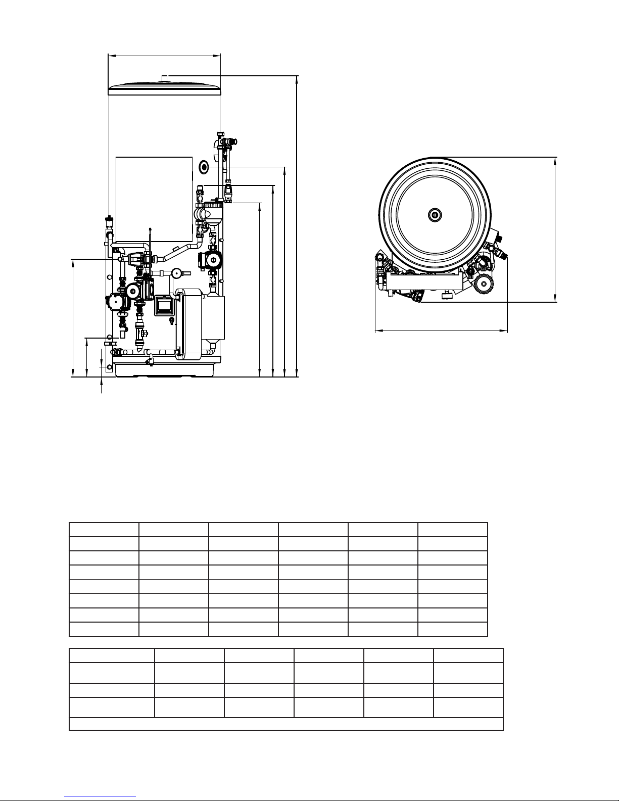
Fig. 8, page 21: shows a G1/2 temperature relief valve with a discharge pipe (D2) having 4 No. elbows and length of 7m from
the tundish to the point of discharge.
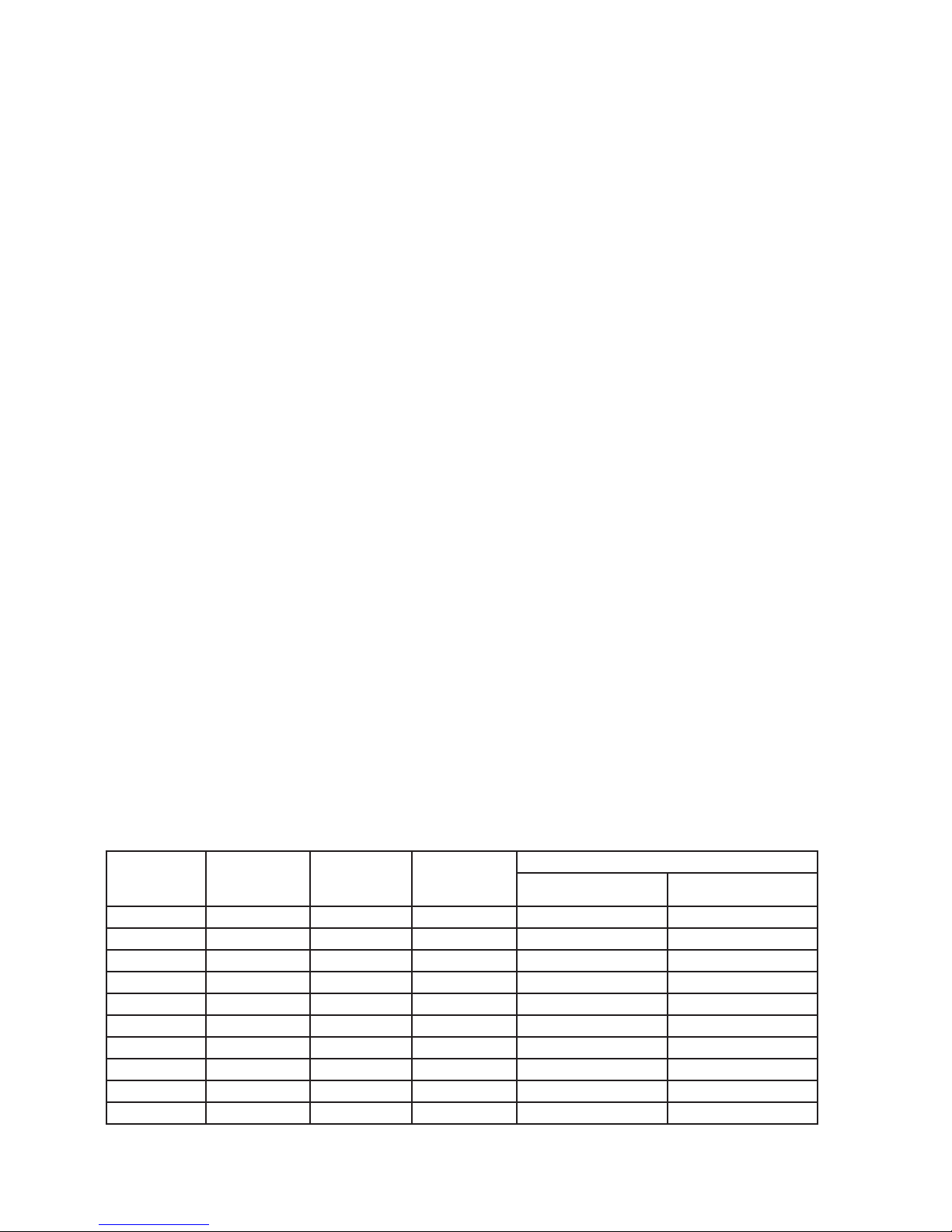
From Table 5, page 21:
Maximum resistance allowed for a straight length of 22mm copper discharge pipe (D2) from a G1/2
temperature relief valve is 9.0m.
Subtract the resistance for 4 No. 22mm elbows at 0.8m each = 3.2m
Therefore the permitted length equates to: 5.8m
5.8m is less than the actual length of 7m therefore calculate the next largest size.
Maximum resistance allowed for a straight length of 28mm pipe (D2) from a G1/2 temperature relief valves equates to 18m.
Subtract the resistance of 4 No. 28mm elbows at 1.0m each = 4.0m
Therefore the maximum permitted length equates to: 14m
As the actual length is 7m, a 28mm (D2) copper pipe will be satisfactory.
WARNINGS:
• Under no circumstances should the factory tted temperature/pressure relief valve be removed other than by a competent
person. To do so will invalidate any guarantee or claim.
• The cold water combination valve assembly must be tted on the water supply to the Pre-plumbed cylinder.
• No control or safety valves should be tampered with or used for any other purpose.
• The discharge pipe should not be blocked or used for any other purpose.
• The tundish should not be located adjacent to any electrical components.
This manual suits for next models
9
Table of contents
Other Ecodan Water Heater manuals
Popular Water Heater manuals by other brands

Flotec
Flotec FP7210-00 Operating & installation instructions

Lochinvar
Lochinvar CLN075075 instruction manual

clage
clage DLX 24 Installation and operating instructions

Rheem
Rheem RUUD Gas Hot Water Supply Heaters Specification sheet

Bradford White
Bradford White RE1 Service manual

A.O. Smith
A.O. Smith ATI-140H-N Service handbook

Bradford White
Bradford White 500-B Specification sheet

Webasto
Webasto thermotop C installation instructions

A.O. Smith
A.O. Smith Water Heater user manual

A.O. Smith
A.O. Smith GPS-75 instruction manual

Hubbell
Hubbell V10 Operating and maintenance manual

TESY
TESY GCV6SL 804420 B11 TSR Instructions for use and maintenance