4. Gear Flashes and Alarm LEDs
MXS Strada features 10 RGB gear flash
LEDs that can be freely configured in a
very flexible way.
CHAPTER 4 GEAR FLASHES A D ALARM LEDS CHAPTER 5 ECU CO ECTIO
10 11
MXS STRADA
MXS Strada also has 6 different alarm
LEDs that you can configure in order to
turn them on or off depending on the
value of the analog or digital inputs, ECU
values, expansion values, GPS
information or math channels.
You can configure them in order to turn
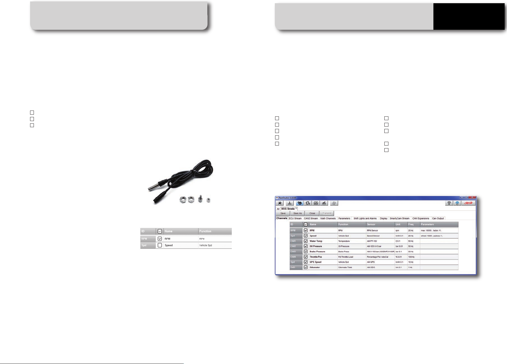
3. Using Race Studio 3, configure MXS
Strada setting that software driver with the
menu shown here down.
The steps are explained in section 10.1.2
5. ECU connection
MXS Strada can sample data from the ECU
of your vehicle.
The list of the ECU available protocols is
published on our site:
http://www.aim-sportline.com/eng/dow-
nload/ ecu-connections.htm
This list includes more than 1000 different
protocols and is constantly updated with
new protocols and upgrades.
When possible, documents explaining how
to configure your ECU to ensure
compatibility between the data flow
transmitted are available, too.
From an hardware point of view, MXS
Strada is compatible with all currently
available connections: CAN, RS232 or K
Line.
The steps to manage the data coming from
the ECU are the following:
1. Determine which hardware
connection is available for your ECU
2. Read the documentation about your
ECU at www.aim-sportline.com and
identify the name of the ECU and the
proper software driver to be specified
For each LED, you can define the RPM value
at which to turn it on and the colour.
You can also define different RPM values
per each gear number.
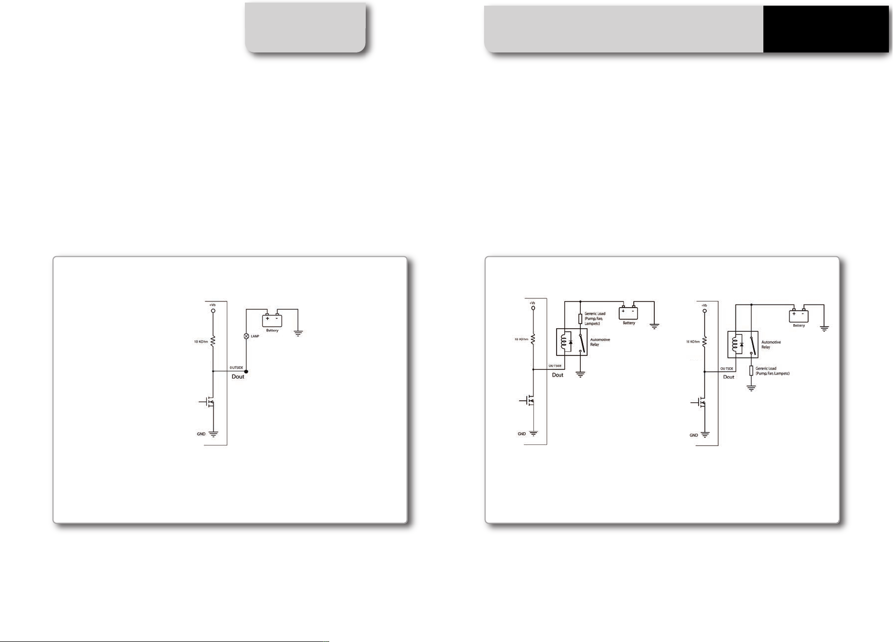
them off when the condition disappears, when
you push a pushbutton or when the test is fi-
nished.
You can associate an alarm LED, a message
and a digital output to each event.
Please, read section 10.1.5 in order to see how
to manage gear flashes and alarm LEDs.
2 2
1
1
2