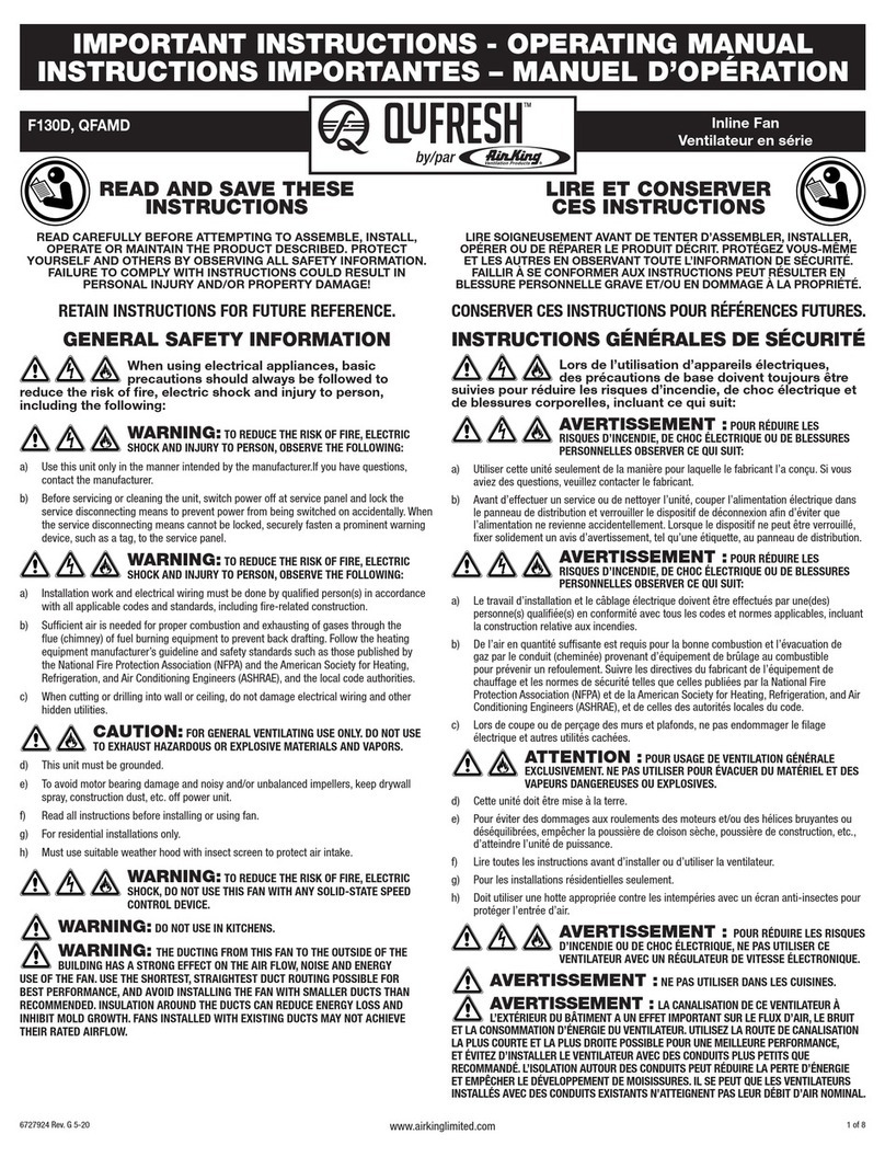
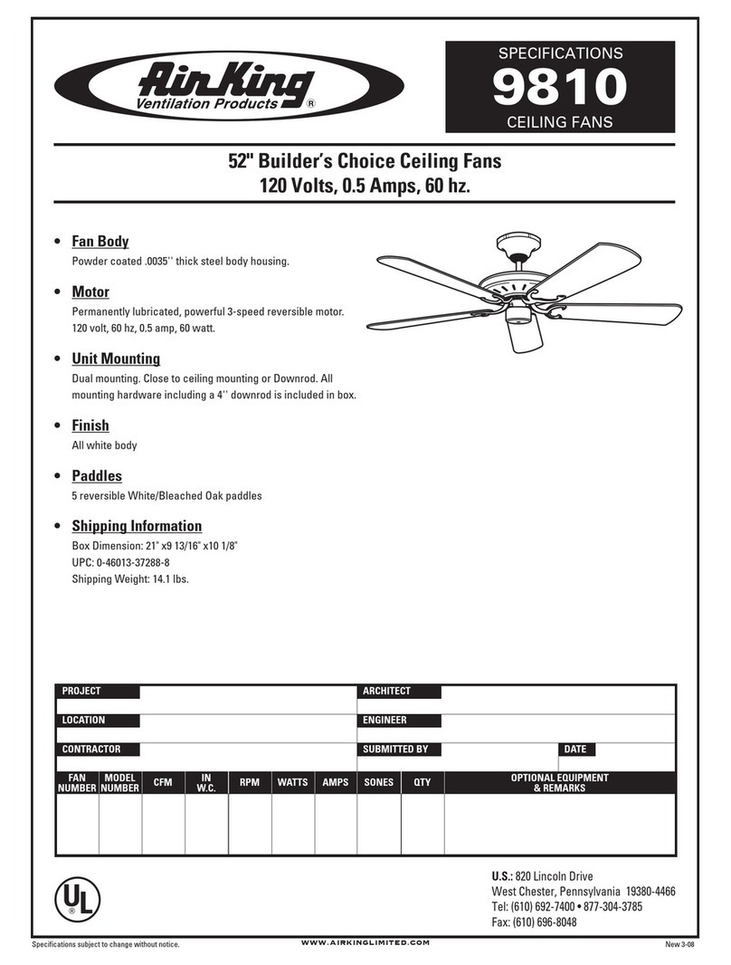
32084070ARev. C 5/00
VENTILADOR DE
PEDESTAL DE 16"
MODELO 4C945J/9126J
Figura 2 Figura 3
Figura 5 Figura 6 Figura 7
Figura 4Figura 1
DESEMPACADO
Al desempacar la unidad, inspecciónela cuidadosamente para ver si no
sufrió algún daño durante el transporte. Verifique que no haya partes flojas,
faltantes o dañadas.
INFORMACIÓNGENERALSOBRESEGURIDAD
1. Cercióresedeque la fuente de electricidad se adapte a los requerimientos
eléctricos del Ventilador.
2. El cordón eléctrico está equipado con una clavija a tierra de tres espigas
que tiene que ser enchufada a un receptáculo del mismo diseño. Bajo
ninguna circunstancia deberá cortarse la espiga a tierra de la clavija. De
existir un receptáculo de pared de dos espigas, deberá reemplazarse
por uno de tres espigas debidamente puesto a tierra e instalado de
conformidad con el Código Nacional de Electricidad y todos los códigos y
ordenanzas locales aplicables. El trabajo deberá hacerlo un electricista
calificado, utilizando exclusivamente alambre de cobre.
NO SE RECOMIENDA EL USO DE UN ADAPTADOR DE TRES A
DOS ESPIGAS. LA CONEXIÓN INDEBIDA PODRÍA CREAR EL
RIESGO DE SER ELECTROCUTADO. EL USO DE TALES
ADAPTADORES NO ESTÁPERMITIDO EN CANADÁ.
3. Siempre que sea posible, evite el uso de extensiones eléctricas. Si
tienen que usarse, minimice el riesgo de sobrecalentamiento
asegurándose de que sean de catalogación UL y del calibre y la longitud
adecuadas. Nunca use una sola extensión para operar más de un
Ventilador.
4. No introduzca los dedos ni objetos extraños en el Ventilador. No
obstruya ni manipule indebidamente el Ventilador mientras esté en
operación.
5. Desenchufeel cordón eléctrico antesdeinstalar o dar servicioalVentilador.
NO DEPENDA DEL INTERRUPTOR DE ENCENDIDO Y APAGADO
COMOEL ÚNICOMEDIOPARAINTERRUMPIRLA ALIMENTACIÓN
ELÉCTRICACUANDO INSTALE O DÉSERVICIO AL VENTILADOR.
SIEMPRE DESENCHUFE EL CORDÓN ELÉCTRICO.
6. Este Ventilador es para uso general EXCLUSIVAMENTE. NO deberá
usarse en localidades potencialmente peligrosas tales como atmósferas
inflamables, explosivas, cargadas de gases o húmedas. NO utilice el
Ventilador en una ventana, ya que la lluvia podría crear un peligro eléctrico.
PARA REDUCIR EL RIESGO DE INCENDIOS O DESCARGAS
ELÉCTRICAS, NO USE ESTE VENTILADOR CON NINGÚN
DISPOSITIVODE CONTROL DE VELOCIDADDEESTADOSÓLIDO.
ENSAMBLAJE
1. Meta el extremo del Tubo de Mayor Diámetro, el que no tiene
agujeros, en Ia Base. Quizás tenga que girar el Tubo al irIo
introduciendo para que ilegue a lo profundo de Ia Base.
2. DEJE EL RESORTE EN LA BOLSA y échelo dentro del Tubo de
Mayor Diámetro.
(Figura 2)
3. Introduzca firmemente el Casquillo de Plástico en el extremo del
Tubo de Extensión que tiene protuberancias.
(Figura 3)
4. Coloque el Retén en el Tubo de Extensión y coloque éste en Ia
Columna.
(Figura 4)
LEA Y GUARDE ESTAS INSTRUCCIONES
LÉALAS CUIDADOSAMENTE ANTES DE INTENTAR ARMAR, INSTALAR, OPERAR O DAR MANTENIMIENTO AL PRODUCTO DESCRITO. PROTÉJASE
A SÍ MISMO Y A LOS DEMÁS OBSERVANDO TODA LA INFORMACIÓN SOBRE SEGURIDAD. ¡NO SEGUIR LAS INSTRUCCIONES PODRÍA RESULTAR
EN LESIONES PERSONALES Y/O DAÑOS A LA PROPIEDAD! GUARDE LAS INSTRUCCIONES PARA REFERENCIAS FUTURAS.
MANUAL DE INSTRUCCIONES DE OPERACIÓN Y PARTES
5. Inserte el Retén del Tubo de Extensión en el Tubo de Mayor
Diámetro. Fijelo con dos Tornillos de Cabeza Phillips #6-5/16"
.
NO
LOS APRIETE EXCESIVAMENTE.
(Figura 5)
6. Coloque Ia Tuerca de Ajuste de Altura en el Tubo de Extensión.
(Figura 6)
ADVERTENCIA:NOAPRIETEIA TUERCA DE AJUSTE DE ALTURA
HASTA QUE SE HAYA INSTALADO EL CONJUNTO DEL MOTOR.
7. Baje el Conjunto del Motor al Tubo de Extensión y girelo hasta que
se asiente el Tubo y los agujeros de Ia parte trasera queden alineados.
Fijelo con el Tornillo tal como se muestra .
(Figura 7)
DESCRIPCIÓN
El Ventilador de Pedestal AirKing de 16" (40.6 cm) es operado mediante una
perilla rotatoria de 3 velocidades; además, es de altura ajustable. Su unidad
giratoriade3paletas, de16" (40.6cm), esaccionada porun motorde condensador
de división permanente con un cordón eléctrico de 6' (1.8 m) pies 18/3.
ESPECIFICACIONES
Motor ............................................ 120V, 50/60Hz
Tamaño de paletas ...................... 16" ( 40.6 cm)
Velocidades ................................. 3
Control ......................................... Conjuntor Rotario
Distribución del lujo de aire ......... 90°Variable
Aprobaciones ..............Catalogación UL. El protector de malla cerrada
del ventilador satisface las normas OSHA.
8. Apriete Ia Tuerca de Ajuste de Altura.
Base
Tubo de
Mayor
Diámetro Resorte
Casquillo de
Plástico
Tubo de
Extensión
Retén
Retén del Tubo
de Extensión
Tornillos de
Cabeza
Phillips
Tuerca de
Ajuste de
Altura
Conjunto
del Motor
MODELO
4C945J/9126J
SPEED
ALTA MEDIA BAJA
CFM 2681 2355 2000
M
3
/s 1.27 1.11 0.94
RPM 1400 1230 1045
Amps .61 .51 .45
Watts 70 60 55
dB A 53 49 44
MODEL 4C945J/9126J
2084070ARev. C 5/00 2
Key Part No. Description Qty.
40
8
7
6
5
9
10
11
4
3
2
29
26
22
21
1
12
13 14 15 17 18
19
23
20
24
25 27
28 31
32
16
Figure 5 Figure 6 Figure 7
5. With Fan Head tilted back, align Ornament of Front Grill so it is
horizontal. Insert bottom of Front Grill into Plastic Rear Grill. Tab at
the bottom of Plastic Rear Grill should be between two Wires of
Front Grill. Snap Front into Rear beginning at the top and working
down both sides.
(Figure 8)
InnovatorsinHomeComfort
TM
Innovatorsin Home Comfort
TM
TAB
ORNAMENT TAB
SNAPS
SNAPS
Figure 8
Pin
Groove
PLASTIC
REAR GRILL
PLASTIC NUT
BLADE
SPINNER
FRONT GRILL
BLADE AND GRILL ASSEMBLY
1. Tilt Fan Head back. Put Plastic Rear Grill on Motor.
(Figure 5)
Align Triangular "∆" cut in the Plastic Rear Grill with triangular
boss on top of front Motor cover. (
Figure 6
)
2. Fully seat Plastic Rear Grill and secure with Plastic Nut turning
Clockwise.
3. Slide Blade onto Motor Shaft. (Align groove on blade hub with pin
on motor shaft.)
(Figure 7)
4. To secure Blade, screw Spinner onto Shaft
Counter Clockwise until tight on Blade hub. OPERATION
OSCILLATION
1. Pull oscillation knob on the rear of motor up and Fan will stay in a fixed
position.
2. Push oscillation knob down and Fan will oscillate from side-to-side.
TILTING
Tilt angle is adjusted by pushing Fan Head back or forth.
HEIGHT ADJUSTMENT
Height of Fan can be adjusted by loosening Height Adjustment Nut,
carefully raising or lowering Fan and firmly retightening nut.
SPEED
Speed is controlled by turning the Rotary Switch in rear of motor housing.
MAINTENANCE
WARNING: ALWAYS UNPLUG THE CORD BEFORE MOVING
OR SERVICING THE FAN.
CLEANING
Use a soft cloth moistened with a mild soap solution. Avoid use of gasoline,
benzine, thinner, chlorinated solvents, harsh cleaners, etc. This will result in
damage to the Fan.
LUBRICATION
Precision bearings are sealed at the factory for life and will not require any
further lubrication.
STORAGE
When not in use, keep unit in a clean, dry place.
WARNING: TO AVOID THE RISK OF FIRE OR ELECTRIC
SHOCK, DO NOT USE FAN WITH ANY SOLID STATE SPEED
DEVICE.
30
33 34 35
36
37
39 38
1 2010815 Height Adjustment Nut 1
2 2010814 Column Retainer (Collar) 1
3 2098040 #6 x 5/16" PPH Screw 2
4 2069006G Large Diameter Pipe 1
5 2011862B Base (Round) 1
6 2060027P Weight (Steel) 1
7 2090038 #8 x 9/16" PPH Screw 6
8 2090092 Locking Screw #8 x 1 PPH 2
9 2098127D Spring (bagged) 1
10 2010809 Push-on Bushing 1
11 2061049 Extension Pipe 1
12 2090019 #7 x 5/8" PTH Screw 1
13 2010803 Switch Knob 1
14 2010677 Motor Cover (Rear) 1
15 2010810 Switch Bracket 1
16 2055087 Switch 1
17 2010121 Oscillating Knob 1
18 2030066GS Motor 1
19 2010710 Motor Cover (Front) 1
20 2090080 Screw # 7 x 5/16" 2
21 2090140 Link Screw 2
22 2010276 Link 1
23 2010808D Neck Bushing 1
24 2010162B Ratchet Plate 1
25 2010258D Neck Piece 1
26 2090586 Elevation Spring 1
27 2090516 Shoulder Bolt 1
28 2090033 Hex Nut 1
29 2090027P Collar Screw #8 x 1/2 PTH 1
30 2090521 Neck Bolt 1
31 2010821 Collar 1
32 2050042W Cord Set 1
33 2011200 Rear Grill 1
34 2010359 Plastic Nut 1
35 2011013 Blade 1
36 2010059 Spinner 1
37 2096214P Front Grill 1
38 2010238 Grill Ornament 1
39 2070024G Bullseye AirKing 1
40 2090529 Wirenut A-O 1
