air-o-steam ELECTRIC COMBI OVENS User manual

9
USA
5938 027 00
INSTRUCTIONS FOR INSTALLATION AND USE
Table of contents Page
- Installation diagram .......................................................... 2
- APPLIANCE IDENTIFICATION
air-o-steam® ELECTRIC COMBI OVENS
6 GN 1/1
260450 260462 260456
260451 260463 260457
°
**
°
**
°
**
400 230 200
2. TABLE 1: TECHNICAL DATA
260462
Rating plate
PNC 9PDX 260462 05
- CONTROL PANEL FIGURES ............................................ 97
- Appliance identification ................................................... 9
I. MAIN FEATURES ............................................................. 10
1. Description of appliance ............................................ 10
2. Table 1: Technical data ................................................. 10
3. Precautions .................................................................. 11
4. Safeguarding the environment................................... 12
4.1 Packaging .............................................................. 12
4.2 Use ......................................................................... 12
4.3 Cleaning ................................................................. 12
4.4 Disposal ................................................................. 12
II. INSTRUCTIONS FOR INSTALLATION ........................... 13
1. Place of Installation .................................................... 13
1.1 Reference standards................................................ 13
1.2 Packaging .............................................................. 13
2. Positioning .................................................................... 13
3. Electrical connection .................................................. 13
3.1 Installing the power supply cable ........................... 14
4. Water mains connection ............................................. 14
4.1 Water supply characteristics .................................. 14
4.2 Water drain system ................................................ 14
5. Safety devices ............................................................. 15
6. Operation check .......................................................... 15
7. Servicing ....................................................................... 15
8. Troubleshooting ........................................................... 15
9. Layout of main components ....................................... 15
III. INSTRUCTIONS FOR USE ............................................ 16
1. Opening the oven door ............................................... 16
1.1 6- and 10-grid models ............................................ 16
1.2 20-GRID models .................................................... 16
2. Closing the oven door ................................................ 16
2.1 6- and 10-GRID models ......................................... 16
2.2 20-GRID models .................................................... 16
3. Description of the control panel ................................ 17
3.1 Introduction ............................................................ 17
3.2 Main controls .......................................................... 17
3.3 Main cooking modes .............................................. 17
3.4 Special cooking modes .......................................... 17
3.5 Additional functions ................................................ 18
USING THE OVEN ................................................................. 19
4. Introduction ................................................................. 19
4.1 Switching the oven on ............................................ 19
4.2 Selecting the controls ............................................ 19
4.3 Manual controls ...................................................... 19
4.4 Automatic controls ................................................. 23
5. Information and error codes ...................................... 26
6. SWITCHING off in the event of a fault ....................... 27
7. Care and maintenance ................................................ 27
7.1 Periodical maintenance of the BOILER ................. 28
7.2 Replacing CONSUMABLE components ................ 29
7.3 Special cleaning instructions ................................. 29

10
USA
5938 027 00
1. DESCRIPTION OF APPLIANCE
This booklet describes a number of appliance models.
For more detailed information about the model in your possession,
refer to "Technical Data" table 1.
The appliance has the following features:
• Digital temperature controlle.
• Thermostatic probe for measuring the core temperature of pro-
ducts (core temperature probe).
• Automatic flush to drain every two hour to prevent the build-up of
lime-scale in the boiler.
• Periodic draining and automatic washing of the boiler to prevent
the build-up of lime-scale.
• Boiler lime-scale level indicator (see corresponding paragraph).
• Oven chamber automatic fast steam drain device for gratins.
• Air-break (anti-backup drain) device to prevent backflows from
the drain system from entering the oven.
• Halogen lighting in the cooking chamber.
• Double-action door opening safety mechanism designed to
protect the user from scalding steam.
• Double-glazed oven door for reduced heat dispersion into the
kitchen and low temperatures on the exterior of the oven.
• Self-diagnostics system indicating oven faults using error codes
(see "Information and error codes ").
I. MAIN FEATURES
GRIDS
BOILER **
SUPPLY VOLTAGE
Maximum load capacities
(food)
Total Watts
PNC *
Shipping depth
CONVECTOR °
Net weight
Shipping w eight
Shipping width
Shipping height
Noise emission data: Noise emissions generated by the appli-
ances described in this booklet do not exceed 70 dB (A).
*Your appliance model is indicated in the box marked PNC on
the Identification dataplate affixed to the bottom left hand side of
the oven.
2. TABLE 1: TECHNICAL DATA
6 GN 1/1 10 GN 1/1 10 GN 2/1 20 GN 1/1 20 GN 2/1
260810 260820 260812 260822 260814 260824 260816 260826 260818 260828
° ° ° ° ° ° ° ° ° °
** ** ** ** ** ** ** ** ** **
208V 3ph
60Hz
32amps
240V 3ph
60Hz
32amp
208V 3ph
60Hz
63amps
240V 3ph
60Hz
63amp
208V 3ph
60Hz
80amps
240V 3ph
60Hz
80amp
208V 3ph
60Hz
100amps
240V 3ph
60Hz
100amp
208V 3ph
60Hz
150amps
240V 3ph
60Hz
150amp
10,1 kW 10,1 kW 17 kW 17 kW 24 kW 24 kW 34,5 kW 34,5 kW 48 kW 48 kW
66 lbs.
(30 kg)
66 lbs.
(30 kg)
110 lbs.
(50 kg)
110 lbs.
(50 kg)
220 lbs.
(100 kg)
220 lbs.
(100 kg)
220 lbs.
(100 kg)
220 lbs.
(100 kg)
440 lbs.
(200 kg)
440 lbs.
(200 kg)
253.53 lbs.
(115 kg)
253.53 lbs.
(115 kg)
319.67 lbs
(145 kg)
319.67 lbs
(145 kg)
504.86 lbs
(229 kg)
504.86 lbs
(229 kg)
533.52 lbs.
(242 kg)
533.52 lbs.
(242 kg)
551.16 lbs
(250 kg)
551.16 lbs
(250 kg)
295.42 lbs.
(134 kg)
295.42 lbs.
(134 kg)
363.76 lbs.
(165 kg)
363.76 lbs.
(165 kg)
538 lbs
(244 kg)
538 lbs
(244 kg)
639.34 lbs.
(290 kg)
639.34 lbs.
(290 kg)
573 lbs
(260 kg)
573 lbs
(260 kg)
37 1/64"inch
(940 mm)
37 1/64"inch
(940 mm)
37 1/64"inch
(940 mm)
37 1/64"inch
(940 mm)
50"inch
(1270 mm)
50"inch
(1270 mm)
37 1/64"inch
(940 mm)
37 1/64"inch
(940 mm)
47 5/8"inch
(1210 mm)
47 5/8"inch
(1210 mm)
40 15/16"inc
(1040 mm)
40 15/16"inc
(1040 mm)
49 5/8"inch
(1260 mm)
49 5/8"inch
(1260 mm)
52 3/8"inch
(1330 mm)
52 3/8"inch
(1330 mm)
79 1/2"inch
(2020 mm)
79 1/2"inch
(2020 mm)
70 7/8"inch
(1800 mm)
70 7/8"inch
(1800 mm)
38 9/16"inch
(980 mm)
38 9/16"inch
(980 mm)
38 9/16"inch
(980 mm)
38 9/16"inch
(980 mm)
44 7/8"inch
(1140 mm)
44 7/8"inch
(1140 mm)
42 1/2"inch
(1080 mm)
42 1/2"inch
(1080 mm)
41 3/4"inch
(1060 mm)
41 3/4"inch
(1060 mm)

11
USA
5938 027 00
3. PRECAUTIONS
• The following terms alert you to potentially dangerous conditions
to the operator, service personnel or to the equipment.
•Danger! This term warns of immediate hazards which will result in
severe injury or death.
•Warning! This term refers to a potential hazard or unsafe
practice which could result in injury or death.
•Notice. This term refers to information that needs special
attention or must be fully understood, even though not dangerous.
• Keep the appliance area free and clear from combustibles.
Warning Fire hazard.
For your safety, do not store or use gasoline or other
flammable, vapors and liquids in the vicinity of this or any other
appliance.
Keep area around appliances free and clear of combustibles
Warning!
Failure to properly vent the oven can be hazardous to the
health of the operator; and will result in operational problems,
unsatisfactory baking, and possible damage to the equipment.
Damage sustained as a direct result of improper ventilation will
not be covered by the Manufacturer's warranty.
NOTICE: INTENDED FOR COMMERCIAL USE ONLY. NOT
FOR HOUSEHOLD USE.
CAUTION HOT SURFACES
CAUTION RISK ELECTRIC SHOCK
CAUTION: Do not locate unit adjacent to any high heat or
grease producing piece of equipment, such as a range top,
griddle, fryer, etc., that could allow radiant heat to raise the
exterior temperature of the Air-O-Steam Oven.
• Carefully read this instruction booklet, as it contains important
advice for safe installation, operation and maintenance.
• Keep this instruction booklet in a safe place for future reference.
• The installation of this unit must conform to local codes or, in the
absence of local codes, to all National Codes governing plumbing,
sanitation, safety and good trade practices.
WARNING: The equipment warranty is not valid unless the
appliance is installed, started and demonstrated under the
supervision of a factory trained installer.
WARNING: The unit must be installed by Personnel who are
qualified to work with electricity and plumbing. Improper installation
can cause injury to personnel and/or damage to the equipment.
The unit must be installed in accordance with applicable codes.
Important: The installation instructions contained herein
are for the use of qualified installation and service
personnel only. Installation or service by other than
qualified personnel may result in damage to the appliance
and/or injury to the operator. FAILURE TO COMPLY
WITH INSTALLATION INSTRUCTION OR IMPROPER
INSTALLATION WILL VOID WARRANTY AND
RESPONSIBLITIES OF THE MANUFACTURE.
• Our appliances have been studied and optimized to give the
highest performance. This appliance is intended for industrial use
only and is specifically designed to cook food. Any other use will be
considered “improper use” and will void the warranty and
manufacturer liability.
WARNING: ANY POTENTIAL USER OF THE EQUIPMENT
SHOULD BE TRAINED IN SAFE AND CORRECT OPERATIONG
PROCEDURES.
WARNING: BEFORE SERVICING, DISCONNET THE
ELECTRICAL SERVICE AND PLACE A RED TAG AT THE
DISCONNECT SWITCH TO INDICATED WORK IS BEING DONE
ON THAT CIRCUIT.
NOTICE: Using any parts other than OEM original spare parts
relieves the manufacturer of all warranty and liability.
NOTICE: Manufacturer reserves the right to change specifications
at any time without notice.
Failure to comply with the above requirement may jeopardise
the safety of the appliance and invalidate the guarantee.
WARNING: DO NOT SPRAY THE OUTSIDE OF THE
APPLIANCE WITH WATER OR CLEAN WITH A WATER JET.
CLEANING WITH A WATER JET CAN IMPREGNAT
CHLORIDES INTO THE STAINLESS STEEL, CAUSING THE
ONSET OF CORROSION.
WARNING: DO NOT USE PRODUCTS CONTAINING
CHLORINE (BLEACH, HYDROCHLORIC ACID ETC.) EVEN
DILUTED, TO CLEAN STEEL SURFACES.
WARNING: DO NOT USE CORROSIVE SUBSTANCES (E.G.
MURIATIC ACID) TO CLEAN THE FLOOR UNDER THE
APPLIANCE.

12
USA
5938 027 00
4. SAFEGUARDING THE ENVIRONMENT
4.1 PACKAGING
• All the packaging materials used are environmentally safe and
friendly. They may be stored without fear or danger. They may be
recycled or burned in a special waste incineration plant. Recyclable
plastic components are marked as follows:
polyethylene : external wrapping film, instructions
PE booklet bag and gas injectors bag
polypropylene: top packaging panels and straps
pp
expanded polystyrene: protective surround elements
PS
4.2 USE
• The appliance has been designed and perfected under laboratory
testing conditions to offer exceptional levels of performance.
However, to minimise energy consumption (electricity, gas and
water), do not leave the appliance in operation for long periods
without food in the oven chamber and avoid conditions that
reduce efficiency (e.g. door open). We also recommend preheating
the appliance immediately prior to use.
4.3 CLEANING
• To minimise the emission of pollutants into the environment,
clean the appliance (externally and, where necessary, internally)
with products that are at least 90% biodegradable.
4.4 DISPOSAL
• Appliances that have reached the end of their service life should
be suitably disposed of.
• The appliance is made from more than 90% recyclable materials
(stainless steel, iron, aluminium, galvanised sheet steel, etc.).
These materials may therefore be scrapped in accordance with
local waste disposal regulations at a conventional recycling plant.
• Make the appliance unusable by cutting off the power cord. Also
remove any compartment or interior closure device fitted on the
appliance to prevent persons from becoming trapped inside.

13
USA
5938 027 00
1.3 UNPACKAGING
• Remove the appliance from the packaging and take away the
protective film that covers the appliance's external panels care-
fully to avoid leaving any trace of glue. If necessary remove the
glue using an a non-corrosive solvent, rinsing it off and drying
carefully.
• Dispose of packaging material in compliance with the regulations
in force in the country where the product is to be used.
1.4 IMMEDIATELY INSPECT FOR SHIPPING DAMAGE
The container should be examined for damage before and during
unloading. The freight carrier has assumed responsibility for its
safe transit and delivery. If damaged equipment is received,
either apparent or concealed, a claim must be made with the
delivering carrier. Apparent damage or loss must be noted on the
freight bill at the time of delivery. The freight bill must then be
signed by the carrier representative (Driver). If the bill is not
signed, the carrier may refuse the claim. The supply can supply
the necessary forms. A request for inspection must be made to
the carrier within 15 days if there is concealed damage or loss that
is not apparent until after the equipment is uncrated. The carrier
should arrange an inspection. Be certain to hold all contents plus
all packing material. Under no circumstances should a damaged
appliance be returned to the manufacturer without prior notice
and written authorization.
2. POSITIONING
• Refer to the installation diagrams at the beginning of this
booklet for the space requirements and connection dimensions of
the appliance.
• Clearance of approximately 23.62" (50cm) must be left between
the appliance’s left side panel and adjacent structures in order to
provide space for maintenance operations when needed; the
right side panel and the rear panel of the appliance must be at
least 1.97" (5cm) from adjacent structures.
• Place the appliance in the required position and level the oven
with a slight pitch toward the rear to help drain water from
chamber using the appropriate bullet feet.
• The appliance is not suitable for built-in installation.
Warning: The oven must be installed on an even (level) non-
flammable flooring and any adjacent walls must be non-flammable.
Recommended minimum clearance are specified in this manaul.
Important:
Make sure steam from the oven’s drain or adjacent
appliances does not enter the aeration vents under the
appliance, designed to cool internal components
located at the bottom of the appliance.
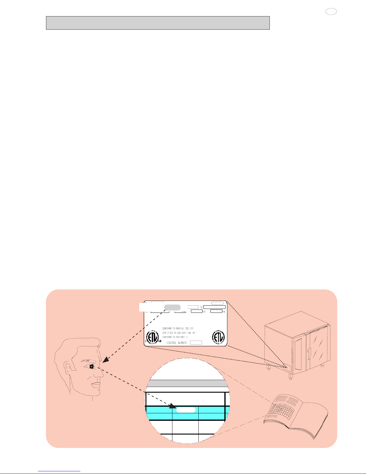
3. ELECTRICAL CONNECTION
• A fused disconnect switch or main circuit breaker (customer
furnished) MUST be installed in the electric supply line for the
appliance. It is recommended that this switch/circuit breaker
have lockout/tagout capability. Before making any electrical
connections to this appliance, check that the power supply is
adequate for the voltage, amperage, and phase requirements
on the rating plate.
• A safety cutout switch of suitable capacity with a contact
breaking distance of at least 3 mm must be fitted upstream of
the appliance.
The cutout switch must be installed near the appliance in the
permanent electrical system of the premises.
• The appliance must be electrically grounded in accordance
II. INSTRUCTIONS FOR INSTALLATION
Important: The oven outer panels must be removed to
perform the operations described in this chapter. Since the
appliance must be switched on to make certain
adjustments, exercise the utmost care when working in the
vicinity of live electrical parts.
1. PLACE OF INSTALLATION
1.1 VENTILATION
The necessity for a properly designed and installed ventilation
system cannot be over emphasized. The ventilation system will
allow the unit to function properly while removing unwanted vapors
and products of combustion from the operating area.
Theappliance mustbe ventedwith aproperly designedmechanically
driven exhaust hood. The hood should be sized to completely
cover the equipment plus an overhang of a least 6"/15.3cm on all
sides not adjacent to a wall. The capacity of the should be sized
appropriately and provisions for adequate makeup air.
Refer to your local ventilation codes. In the absence of local codes,
refer to the National ventilation code titled, “Standard for the
Installation of Equipment for the Removal of Smoke and Grease
Laden Vapors from Commercial Cooking Equipment”, NFPA-96-
Latest Edition.
It is recommended that the ventilation system and duct work be
checkedat prevailingintervals asspecified bythe hood manufactured
• The appliance must only be installed in adequately ventilated
premises.
NOTICE: Proper ventilation is the owner's is responsibility. Any
problem due to improper ventilation will not be covered by the
warranty.
1.2 REFERENCE STANDARDS
Note: The electric supply installation must satisfy the requirements
of the appropriate statutory authority, such as the National
Electrical Code (NEC) ANSI/NFPA70, (U.S.A..): the Canadian
Electrical Code, CSA C22.2; or other applicable regulations.
Note: The electric supply connection must meet all national and
local electrical code requirements.
Note: The installation of this unit must conform to local codes or,
in the absence of local codes, to all National Codes governing
plumbing, sanitation, safety and good trade practices, and to the
National Gas Code ANSI Z223.1.
• Local codes regarding installation vary greatle from one area to
another. This equipment is to be installed to comply with the
applicable federal, state or local codes.
The installation instructions contained herein are for the use of
qualified installation and service personnel only. Installation or
service by other than qualified personnel may result in damage to
the appliance and/or injury to the operator.
FAILURE TO COMPLY WITH INSTALLATION INSTRUCTION
OR IMPROPER INSTALLATION WILL VOID WARRANTY AND
RESPONSIBLITIES OF THE MANUFACTURE.
The National Fire Protection Association, Inc states in its NFPA
96 latest edition that local codes are the "authority having
jurisdiction" when it comes to installation requirements for
equipment. Therefore, installations should comply with all local
codes.
Table of contents
Popular Oven manuals by other brands

Brandt
Brandt FC 222 user manual

aumate
aumate TOA20M04N-1E instruction manual

Maytag
Maytag CWE4100AC - 24" Single Electric Wall Oven Dimension Guide

Kernau
Kernau KBO 1076 S PT B instruction manual

Bosch
Bosch HB 37 N Series User manual and installation instructions

Electrolux
Electrolux EOD5420AA user manual