AIR SYSTEMS CVF-8AC50 User manual

C US
®
OPERATING INSTRUCTIONS AND REPLACEMENT PARTS
Models:
CVF-8AC, CVF-8AC50, CVF-6ACAN, CVF-15ACAN, CVF-25ACAN
CVF-8DC, CVF-6DCAN, CVF-15DCAN, CVF-25DCAN
AIR SYSTEMS INTERNATIONAL, INC.
829 Juniper Crescent, Chesapeake, Va, 23320
Telephone (757) 424-3967
Toll Free 1-800-866-8100
Fax No. (757) 424-5348
www.airsystems.com.
e-mail: [email protected]
This manual must be read carefully and followed by all persons who have or will have the responsibility
for using or servicing this equipment. This equipment will perform as designed only if used according
to the instructions. Otherwise it could fail to perform as designed, causing personal injury or death.
WARNING

The Saddle Vent® Ven la on System
Typical Saddle Vent® Setup Procedure
Place fan or blower a minimum of
5 . (1.6m) from manhole opening
Blower or Fan
90° Elbow
Manhole
Opening
Manhole Lid
Universal Mount
Saddle Vent®Select a blower or fan based on environmental
condi ons and the size of the confi ned space.
For informa on or guidance in selec ng the
proper set-up, please contact Customer Service.
STEP 1) Install 6 . (1.8m) duct on blower or fan
STEP 2) Install 90° elbow on top of Saddle Vent®
STEP 3) Install duct on bo om of Saddle Vent®
STEP 4) Install universal mount on Saddle Vent® and
set in place with manhole lid for support
STEP 5) Install duct from blower to 90° elbow
STEP 6) Turn on blower or fan
Warning: For explosive environments,
follow ANSI/API 2015 and 2016 procedures
The Saddle Vent® is a registered trademark of Air Systems Interna onal, Inc.
The Conduc ve Saddle Vent® is covered by U.S. and Foreign Patents
WARNING: HAZARDOUS LOCATION OPERATIONS
Use an explosion-proof or intrinsically safe blower or fan,
conduc ve duc ng, and The Conduc ve Saddle Vent® System.
A ach all grounding wires and assure a complete circuit to the
blower or fan in order to remove sta c charges.
2

SAFETY PRECAUTIONS
READ AND FOLLOW ALL INSTRUCTIONS BELOW
All ven la on procedures should comply with federal, state, and local regula ons. Air
quality should be tested prior to ven la ng a confi ned space. A purge chart is provided in this
manual help assist in es ma ng the approximate me needed to ven late confi ned spaces.
Air quality should be tested con nuously during confi ned space occupancy to ensure a stable
atmosphere and worker safety because atmospheric condi ons can change rapidly. Addi on-
al procedures and recommenda ons are available from federal, state, and local agencies. DO
NOT operate these fan unit in a ver cal posi on or with the fl ange or guards removed.
WARNING
Fan and blower models with the “EX” or “X” designa on are
the only models approved for use in hazardous loca ons.
If vola le or explosive vapors are suspected, use Air Systems’ explosion proof electric blower,
Model No. SVB-E8EXP, explosion proof in-line fan, Model No. SVF-10EXP, explosion proof con-
tractors fan, Model No. CVF-8EXP or Air Systems’ intrinsically safe pneuma c blower, Model
No. SVB-A8.
Note: For confi ned space ven la on in non-hazardous loca ons, use Air Systems’ confi ned
space ven la on kit, Model SV-CUP. For hazardous loca ons use ven la on kit, Model SV-
CUPCND along with one of the above explosion proof blowers or fans.
3

General Set-Up and Operation
For CVF-8AC, CVF-8AC50, and CVF-8DC Models
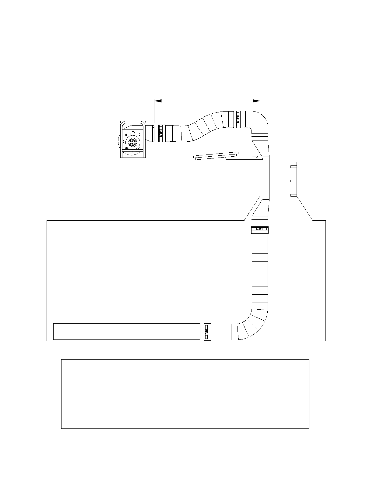
1) Place fan in a clean fresh air environment.
2) Air quality of the conned space should be tested prior to ventilation. If air quality of the conned space is
unacceptable, consult a trained professional.
3) Inspect fan for damaged or worn parts and ducting for air leaks prior to fan operation.
4) Install duct cuff to exhaust ange and secure. Keep bends and kinks in ducting to a minimum to maximimize
air ow. If canister model is used, secure canister with connect straps, open lid and pull out ducting. Inspect
for air leaks.
5) Set fan upwind from the work location and a minimum of 5 ft. from the manhole opening.
6) Connect fan to power source.
AC versions require 115 VAC/60Hz, 15 amp service or 220 VAC/50Hz.
Note: If an extension cord is required, the minimum recommended size is 14 AWG up to
25 ft. For further information refer to the National Electric Code Tables, Article 400.
7) Push ON/OFF switch to “I” position on CVF-8AC and CVF-8DC models.
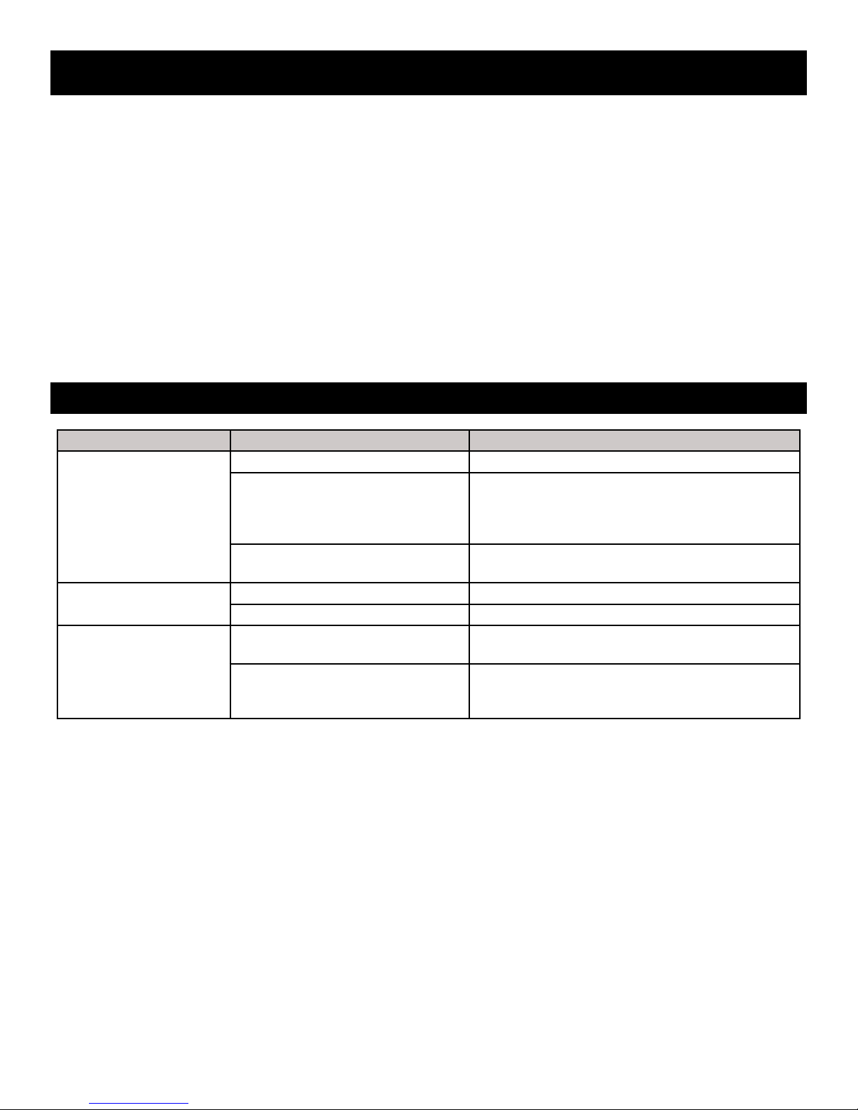
PROBLEM POSSIBLE CAUSE SOLUTION
Excessive vibration
Air intake blocked Turn fan off and clear debris from intake.
Possible internal damage
Turn off and inspect fan blades, shaft, and housing
for debris, damage, and loose screws.
Note: Never run fan for extended periods without
installing duct on the exhaust ange.
Possible external damage Turn fan off and inspect for loose guards, broken
welds, etc.
Circuit breaker trips
CVF-8AC series only
Voltage output insuf cient Test outlet with volt meter.
Extension cord improperly sized Use 14 AWG extension cord up to 25 ft.
Fan will not run
CVF-8DC only
Blown fuse (DC version only) Check and replace. Use only a 20A/32 VDC slow
blow fuse.
Battery connection
Ensure proper connection from battery clips to bat-
tery terminal posts. On battery pack units, recharge
battery.
4
Troubleshooting

System Components - AC Voltage Contractor Fans
Models: CVF-8AC Series
An optional GFI (Ground Fault Interrupter) plug can be supplied to comply
with the 1996 NEC code requirement: Section 305-6. Order P/N ELCB013.
This part number includes both the GFI plug and a 7’ power cord.
C US
®
ITEM # DESCRIPTION PART #
1DISCHARGE GUARD CVF-FG
2INTAKE GUARD CVF-RG
3DUCT CANISTER LATCHING POST CVF-POST
4ON/OFF SWITCH CVF-SWITCH
5POWER CORD ELCB012
6DUCT CANISTER WITH 6’ OF DUCT CVF-CAN6
7DUCT CANISTER WITH 15’ OF DUCT CVF-CAN15
8DUCT CANISTER WITH 25’ OF DUCT CVF-CAN25
9115 VAC/60Hz MOTOR MTR043CN
MOTOR TYPE 1/3 HP (2.47 kw) electric, 115 VAC/60Hz, 2.6 amps, Single Speed, 3450 RPM, Thermally Pro-
tected, Max. Ambient Temperature: 104° Fahrenheit
OUTLET SIZE 8” Diameter (203mm)
FLOW RATES
Free Air: 974 cfm
15 ft. duct with one 90° bend: 786 cfm
15 ft. duct with two 90° bends: 661 cfm
5
Specications

MOTOR TYPE 1/3 HP (2.47 kw) electric, 220 VAC/50Hz, 1.2 amps, Single Speed, 3450 RPM, Thermally Pro-
tected, Max. Ambient Temperature: 104° Fahrenheit
OUTLET SIZE 8” Diameter (203mm)
FLOW RATES
Free Air: 870 cfm
15 ft. duct with one 90° bend: 725 cfm
15 ft. duct with two 90° bends: 715 cfm
ITEM # DESCRIPTION PART #
1DISCHARGE GUARD CVF-FG
2INTAKE GUARD CVF-RG
3DUCT CANISTER LATCHING POST CVF-POST
4ON/OFF SWITCH CVF-SWITCH
5CVF-8AC50 POWER CORD (“E+F” STYLE PLUG)(CEE 7/7) ELCB012EF
5A CVF-8AC50G POWER CORD (“G” STYLE PLUG)(BS1363 UK) ELCB012G
6DUCT CANISTER WITH 6’ OF DUCT CVF-CAN6
7DUCT CANISTER WITH 15’ OF DUCT CVF-CAN15
8DUCT CANISTER WITH 25’ OF DUCT CVF-CAN25
9220 VAC/50Hz MOTOR MTR043CN50
6
System Components - AC Voltage Contractor Fans
Models: CVF-8AC50 Series
Specications

MOTOR TYPE 12 VDC, 1/4 HP, Thermally Protected, 3450 RPM, 20 amp/32 VDC Slow Blow Fuse
OUTLET SIZE 8” Diameter (203mm)
FLOW RATES
Free Air: 848 cfm
15 ft. duct with one 90° bend: 702 cfm
15 ft. duct with two 90° bends: 590 cfm
ITEM # DESCRIPTION PART #
1DISCHARGE GUARD CVF-FG
212 VDC ELECTRIC MOTOR MTR044CN
3FAN BLADE ASSEMBLY CVF-FAN
4INTAKE GUARD CVF-RG
520 AMP SLOW BLOW FUSE ELF022
6DUCT CANISTER LATCHING POST CVF-POST
7ON/OFF SWITCH CVF-SWITCH
8RED BATTERY CLAMP ELA083R
9BLACK BATTERY CLAMP ELA083B
10 DUCT CANISTER WITH 6’ OF DUCT CVF-CAN6
11 DUCT CANISTER WITH 15’ OF DUCT CVF-CAN15
12 DUCT CANISTER WITH 25’ OF DUCT CVF-CAN25
7
Specications
System Components - DC Voltage Contractor Fans
Models: CVF-8DC Series

ITEM # DESCRIPTION PART #
1RUBBER LATCH CVF-RHOOK
2RUBBER LATCH SECURING HOOK CVF-UPOST
310-32 X 1” SCREW FS1032X100
410-32 X 1/2” SCREW FS1032X050
5RED DUCT CANISTER, NON-CONDUCTIVE CVF-CAN-ND
6RED DUCT ADAPTER, NON-CONDUCTIVE CVF-CANA
78” HOSE CLAMP SV-HC8
86’ NON-CONDUCTIVE DUCT SVH-6
915’ NON-CONDUCTIVE DUCT SVH-15
10 25’ NON-CONDUCTIVE DUCT SVH-25
11 #10 STAINLESS STEEL FLATWASHER FW#10SS
12 RED DUCT CANISTER LID, NON-CONDUCTIVE CVFCANL
13 3/16” POP RIVET FR3/16XMAL
14 DUCT CANISTER LID STRAP CVF-BELT
15 10-32 NUT WITH NYLON INSERT FN1032ESN
16 PLASTIC LATCHING POST CVF-POST
8
System Components - Non-Conductive Duct Canister
Models: CVF-CAN Series

9
Air Systems’ manufactured equipment is warranted to the original user against defects in workmanship or materials under
normal use for one year from the date of purchase. Any part which is determined by Air Systems to be defective in mate-
rial or workmanship will be, as the exclusive remedy, repaired or replaced at Air Systems’ option. This warranty does not
apply to electrical systems or electronic components. Electrical parts are warranted, to the original user, for 90 days from
the date of sale. During the warranty period, electrical components will be repaired or replaced at Air Systems’ option.
NO OTHER WARRANTY, EXPRESSED OR IMPLIED, AS TO DESCRIPTION, QUALITY, MERCHANTABILITY, FIT-
NESS FOR A PARTICULAR PURPOSE, OR ANY OTHER MATTER IS GIVEN BY AIR SYSTEMS IN CONNECTION
HEREWITH. UNDER NO CIRCUMSTANCES SHALL THE SELLER BE LIABLE FOR LOSS OF PROFITS, ANY OTHER
DIRECT OR INDIRECT COSTS, EXPENSES, LOSSES, OR DAMAGES ARISING OUT OF DEFECTS IN, OR FAILURE
OF THE PRODUCT OR ANY PART THEREOF.
The purchaser shall be solely responsible for compliance with all applicable Federal, State and Local OSHA and/or MSHA
requirements. Although Air Systems International believes that its products, if operated and maintained as shipped from
the factory and in accordance with our “operations manual”, conform to OSHA and/or MSHA requirements, there are no
implied or expressed warranties of such compliance extending beyond the limited warranty described herein. Product
designs and speci cations are subject to change without notice. Rev. 2, 12/98
Air leaks are not covered under warranty except when they result from a defective system component, i.e. an on/off valve
or regulator or upon initial delivery due to poor workmanship. Air leaks due to poor delivery or damage will be covered un-
der delivery claims. Minor air leaks are part of routine service and maintenance and are the responsibility of the customer
just as are lters and oil changes.
Warranty

10
Notes:

11
Notes:

AIR SYSTEMS INTERNATIONAL,
INC.
829 Juniper Crescent, Chesapeake, Va, 23320
Telephone (757) 424-3967
Toll Free 1-800-866-8100
Fax No. (757) 424-5348
http://www.airsystems.com
Printed in the U.S.A. ©Copyright Air Systems International, Inc. 2018 All Rights Reserved
Manual No. BLWR043
Rev. 6 July 2018
This manual suits for next models
8
Table of contents
Other AIR SYSTEMS Fan manuals