10
INSTALLATION INFORMATION
General. For new installations it is recommended to follow the following guidelines:
Make sure to install the system in accordance with all local electrical and plumbing codes.
Sizes of each suction line from the operatories differ between MOJAVE systems. See Site Requirements
provided on page 12.
The suction line should not have any sharp right angle bends and must be sloped a minimum of ¼
inch for every 10 feet toward the separation tank.
The drain on the base of the separation tank must be connected to a vented or an open floor drain
capable of handling 10 gallons in 30 seconds. Drain pipe size 1½inch schedule 40.
The drain line should be a short run with a minimum slope of ¼ inch for every 10 feet toward the
drain (avoid any sharp right angle bends).
Vent line requirements differ among MOJAVE systems. See Site Requirements.
Make sure to install the supplied exhaust vent assembly to the bottom end of the facility vent line.
The vent should be sloped ¼ inch per 10 feet towards the pump. Vent lines must be capable of
handling vapors and liquids.
The outside vent must be protected from rain and animals.
A flexible air exhaust hose is provided to connect to the 2 inch diameter vent pipe and heat exchang-
er. Hose clamps are provided to secure hose to heat exchanger and pipe.
Wash-out water supplied via ½inch copper tubing terminated with a ½inch FNPT shut-off valve
providing water pressure between 20 and 100 psi.
Wash-out port on the tank top is a 3∕8inch push to connect elbow that connects to the water supply
via supplied 10 foot 3∕8inch Poly tubing and ½MNPT x 3∕8inch push to connect adapter.
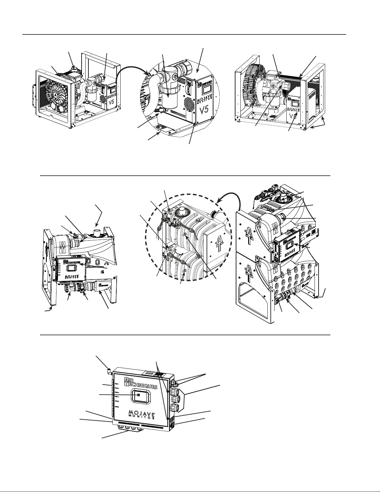
As shown by Figure 1, the Master Controller is delivered mounted on the front chassis of the fully
assembled MT10-M or CT20-M tank associated with the system. In addition to the water connection
at the washout solenoid, electrical and vacuum connections must also be made.
Accessory packs and system installation kits shipped with associated MOJAVE systems are listed
below. Refer to the Installation Section for a listing of components supplied with each kit and the
instructions necessary to install specific MOJAVE systems.
Run a network cable into the room where you will set up your Mojave to allow connection to the
Vision Monitor.
Constant power MUST be supplied to the system at all times. Applications where power cannot be
constantly provided, such as in many mobile dentistry environments, are not recommended for use
with this system and will void the warranty.
Grounding reliability can only be achieved when the Master
Controller is connected to a HOSPITAL GRADE receptacle.
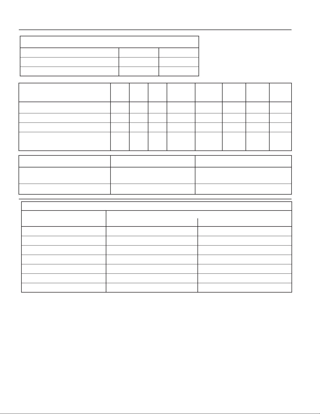
MOJAVE Accessory Packs and System Installation Kits
Part No. Description Included With
H5210 MT10-M 120V Tank Accessory Pack Ships with every 120V MT10-M tank
H5479 MT12-M 220V Tank Accessory Pack Ships with every 220V MT12-M tank
H5170 MOJAVE V3M, V5M and V7M Pump Accessory Pack Ships with every V3M Pump, V5M Pump and V7M Pump
H5307 MOJAVE V3M, V5M, V7M without Heat Exchanger
Pump Accessory Pack” Ships with every V3M Pump, V5M Pump and V7M Pump
MIK2 MOJAVE Dual System Installation Kit Ships with every 2V3M, 2V5, 2V7M, 2V3MCT and 2V5MCT System
MIK4 MOJAVE Triple and Quad System Installation Kit Ships with every 3V5M and 4V5M System
H5243 CT20-M 120V Tank Accessory Pack Ships with every 120V CT20-M tank
H5289 CT22-M 220V Tank Accessory Pack Ships with every 220V CT22-M tank