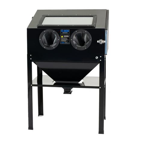
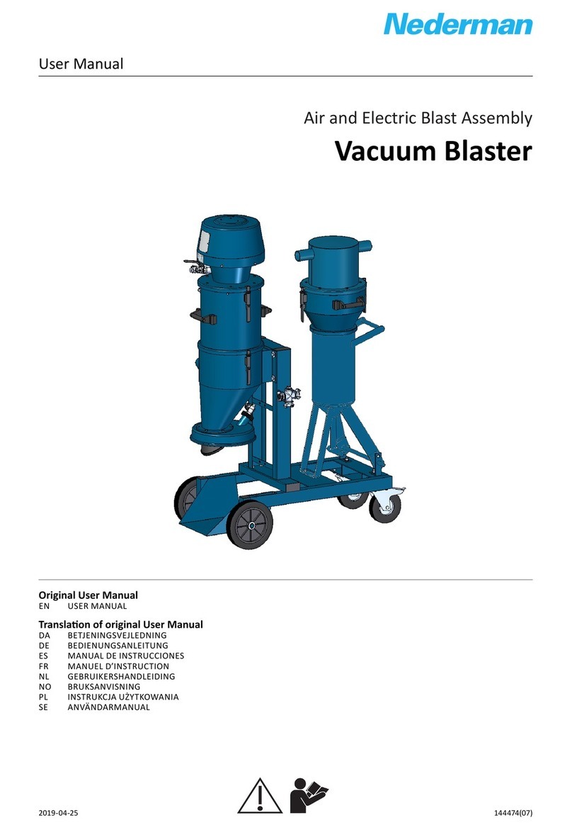
AIRBLAST 1070 PNE User manual

OPERATOR’S MANUAL
AIRBLAST 1070 PNE
VACUUM BLASTING MACHINE

NOTICE
This user’s manual describes how to handle and operate the subject machine(s) to ensure
safe operation, optimum work economy and long service life.
Read this book before putting the machine into operation to ensure correct handling,
operation and proper maintenance from the beginning.
Keep this book available for the operator(s) and make sure that the unit is operated and
maintained according to the instructions.
In all correspondence always mention the unit type and the complete serial number shown on
the data plate.
The owner is responsible to keep the machine(s) in a safe operating condition.
If any statement in this book especially with regard to safety does not comply with local
legislation, the stricter of the two shall apply.
The author disclaims any responsibility from the use or misuse of information contained in
this publication.
Copyright 2012
By AIRBLAST BV
All rights reserved
This Handbook or any parts thereof may not be reproduced in any form without the written
consent of the copyright owners.

USER MANUAL VACUUM BLASTING MACHINE 1070 PNE AB
Revision 1 January 2012 page 0.0
Table of contents page
1. Introduction 1.1
2. Responsibilities of owner and personnel 2.1
3. Safety 3.1
3.1 Safety precautions 3.1
3.2 Safety provisions 3.4
3.3 Warning/ caution Information 3.5
4. Technical data 4.1
5. Parts list 5.1
6. Transport 6.1
7. Machine function 7.1
8. Setting up for operation 8.1
8.1 Installation instructions 8.1
8.2 Operation instructions 8.2
8.3 Adjustment 8.2
8.3.1 Setting the pressure 8.2
8.3.2 Adjustment of the abrasive control valve 8.3
9. Operation of the machine 9.1
9.1 Inspection procedure before starting up 9.1
9.2 Operation instructions 9.1
9.3 Taking the machine out of operation 9.3
10. Maintenance 10.1
11. Trouble shooting 11.1
12. Parts 12.1
13. Pneumatic diagram 13.1

USER MANUAL VACUUM BLASTING MACHINE 1070 PNE AIRBLAST
Revision 1 January 2012 page 1.1
1. Introduction
The AIRBLAST's Vacuum Blasting technology is a new concept for cleaning many types of
surfaces quickly, thoroughly and without environmental pollution.
The AIRBLAST 1070 PNE machine is designed as a high capacity direct pressure-blasting
machine featuring a continuous blast media feed system. This feature allows the machine to
be kept compact and lightweight but with a minimum down time for media loading and
machine handling.
During the blast operations, the dust and debris are separated from the re-usable abrasive
for simple disposal. Only the cleaned blast media recycles to provide optimal surface prepa-
ration.

USER MANUAL VACUUM BLASTING MACHINE 1070 PNE
AIRBLAST
Revision 1 January 2012 page 2.1
2. Responsibilities of owner and personnel
* Do not operate the machine before reading this manual.
* Good co-operation and co-ordination is necessary, when more than one operator is
required.
* Do not alter or modify the machine without a written permission of the manufacturer.
* Inspection and maintenance must be done as described in this manual.
* A competent and responsible operator is essential to an efficient use of the machine.
* Local labour and safety laws and regulations must always be observed.
* The technical personnel should be familiar with all recurrent situations, during assembly,
disassembly and maintenance of the machine.
* The operator should be familiar with all recurrent situations while operating the machine.
* If operator or technicians observe faulty or dangerous equipment or practices, they must
inform the owner or other responsible person immediately.
* The safety aspects should be known. Using the machine safely comes first.
* The working place should be free of obstacles.
* Improper use of the machine is not allowed.

USER MANUAL VACUUM BLASTING MACHINE 1070 PNE AIRBLAST
Revision 1 January 2012 page 3.1
3. Safety
3.1 Safety precautions
The following are general safety precautions for use before and during operation of the
AIRBLAST 1070 PNE. These precautions should be understood and followed to prevent
accidents, bodily injury, or damage to the equipment. Personal safety equipment used should
be of an approved type.
Safety precautions:
* Wear safety goggles, gloves, and hearing protection at all times during blasting.
* Despite the very high level of containment, suitable respirators must be worn when
removing hazardous or toxic coatings.
* Before each use carefully check the equipment for damaged loose or frayed cables, hoses,
or components. Rectify any problems before use.

USER MANUAL VACUUM BLASTING MACHINE 1070 PNE
AIRBLAST
Revision 1 January 2012 page 3.2
* All hose connections with claw couplings should be provided with safety clips.
* Do not use worn brushes as these will allow blast media and dust to escape into the
atmosphere. Check the brushes for service ability.
* Place the blast gun brush flat against the surface to be treated before pulling the trigger.
Release the trigger and wait a few seconds for abrasive flow to stop before lifting the blast
gun from the surface.
* Do not attempt to use this equipment without proper lighting and visibility.
* When opening and cleaning the dust compartment, or otherwise performing any work on
the equipment where dust is generated, always wear eye protection and a proper
respirator. Technicians should do this only.

USER MANUAL VACUUM BLASTING MACHINE 1070 PNE AIRBLAST
Revision 1 January 2012 page 3.3
* Do not operate this or similar equipment in an area where explosive gasses are present.
* Never aim the blast head at any part of the human body.
* Do not remove the safety guards from the machine.

USER MANUAL VACUUM BLASTING MACHINE 1070 PNE AIRBLAST
Revision 1 January 2012 page 3.4
3.2 Safety provisions
The machine is provided with the following safety provisions:
* Pressure relief valve (91)
* Spring clips (78) for the claw couplings (87)
* Swivel castor with brake (52)

USER MANUAL VACUUM BLASTING MACHINE 1070 PNE AIRBLAST
Revision 1 January 2012 page 3.5
3.3 Warning/caution information
DO NOT PERFORM BLASTING DURING RAIN OR VERY HUMID
CIRCUMSTANCES
COIL CABLES'S AND HOSES CAREFULLY WHEN EVER THE MACHINE
IS STORED
UNCOIL ALL AIR HOSES PROPERLY WHEN ATTACHED TO THE
MACHINE AND PLACE SAFETY CLIPS TO ALL COUPLINGS BEFORE
APPLYING PRESSURE TO THE HOSES INSPECT REGULARLY NOZZLE,
HOSES AND BRUSHES ETC. FOR WEAR.
TAKE IN ACCOUNT THAT THE NOZZLE WEARS OUT.
- THE NEEDED AMOUNT OF AIR INCREASES
- THE WEAR ON OTHER PARTS OF THE BLASTHEAD INCREASES
REPLACE NOZZLE WHEN WORN OUT LARGER THAN .2900"/7,4 M/M
NEVER AIM THE BLAST HEAD AT ANY PART OF THE HUMAN BODY

USER MANUAL VACUUM BLASTING MACHINE 1070 PNE AIRBLAST
Revision 1 January 2012 page 4.1
4. Technical data
Dimensions: 735x1565x1660 mm
29 x61.6 x 65.4 Inches
Gross abrasive capacity: 38litres 10 US.Gal.
Weight (machine only empty): 525 kg. 1155 lb.
Shipping weight (machine only empty) 675 kg. 1155 lb.
- 15 m. hose assy & accessories: 30 kg. 66 lb.
- 10 m. hose for extension: 20 kg. 44 lb.
- 20 m. hose for extension: 40 kg. 88 lb.
Recommended compr. capacity: 8 bar, 10 m3/min
116 PSI, 375 cfm
Max. blasting pressure (pr.vessel) 8 bar 116 PSI
Max. abrasive size: 1.4 mm. 12 Mesh
Recommended Abrasive: chilled iron and steel
grit, Aluminium oxyde
Not recommended: non-recyclable abrasives.
Do not use sand!
NOTE whenever lightweight recyclable abrasives has to be used like; glass, walnut shells or
plastic use the special designed light weight abrasive dust separator.
Hose lengths
The standard hose length is 15 m.
Extension sets of 10 m. and 20 m. are available.
The maximum hose length is 45 m.

USER MANUAL VACUUM BLASTING MACHINE 1070 PNE AIRBLAST
Revision 1 January 2012 page 5.1
5. Parts List
11. Sieve
12. Clip
16. Abrasive dust separator
18. Sieve small
23. Blast head
25. Nozzle
27. Blast tube flat
30. Brush holder
33. Brush ring flat
36. Trigger
42 Housing abrasive control valve
38. Plug
40. Wing bolt
102. Abrasive control valve
45. Vacuum hose
48. Filter
55b. Pressure gauge venturi
55a. Pressure gauge blasting pressure
55c. Pressure gauge inlet air
56b. Button filter cleaning
57b. Pressure regulator venturi
57a. Pressure regulator blasting pressure
60. Dust bag
61. Control hoses
73. Blast hose
74. Vacuum hose
76. Claw coupling
91. Pressure relief valve
92. Venturi
93. Main air valve
95. Dust exhaust valve
82. Claw coupling
125. Pressure vessel

USER MANUAL VACUUM BLASTING MACHINE 1070 PNE
AIRBLAST
Revision 1 January 2012 page 6.1
6. Transport
The bottom of the machine frame is provided with two tubular sleeves for the forks of a Fork
lift truck. In this way the machine can be transported safely. Another possibility is to move
the machine by crane or hoist. For this reason two lifting lugs are incorporated in the frame
machine.
In case of transport always make sure that dust valve is completely closed.

USER MANUAL VACUUM BLASTING MACHINE 1070 PNE AIRBLAST
Revision 1 January 2012 page 7.1
7. Machine function
During the blasting operation the abrasive is propelled at a high speed through the blast
head against the surface to be cleaned. After cleaning the surface, the abrasive - together
with the rust or coating removed from the surface - is vacuumed back into the machine
through the suction hose.
In the dust separator, the exhaust speed of the abrasive and dust is reduced by means of
collision pads. Below the last collision pad is a fine wire mesh screen through which the dust
and small spent abrasive will pass. Since these pads are placed at an angle, gravity causes
the re-usable abrasive to fall back into the hopper above pressure vessel. Any larger waste
particles will be caught by the sieve.
Below the last collision pad with fine mesh there is an exhaust opening leading to the filter
section. The dust is drawn back to the filter chamber where the heavier dust falls directly into
the bottom of the dust chamber and the remainder is drawn to the filters. The fine dust clings
to the filters and the clean air is blown back into the atmosphere through the vacuum
generator. To prevent the filters becoming clogged, they can be cleaned by pushing the knob
on the dashboard indicating “filter cleaning” a few times each four hours (Filter back-flush
system). Depending upon the abrasives being used and the surface being blasted the filters
must be cleaned less or more frequent.
The single-chamber pressure vessel functions as follows: By means of a pneumatic solenoid
and trigger action, the pressure vessel is pressurised. The pressure vessel is always
pressurised as long as the trigger is activated. Now the abrasive, under pressure, passes
through the abrasive control valve into the blast hose. At the end of the blast hose the
abrasive passes a nozzle and gets propelled against the surface inside a blast head.
Whenever the upper chamber is depressurised, the valve on top of it will open and the
abrasive stored above it will flow in to the upper chamber.


USER MANUAL VACUUM BLASTING MACHINE 1070 PNE AIRBLAST
Revision 1 January 2012 page 8.1
8. Setting up for operation
8.1 Installation instruction
Connect the machine to a compressor with a minimum capacity of 10 m3/min (375 CFM) and
a maximum pressure of 9 bar (130 PSI) at the compressor. The pressure vessel of the
machine has not been designed to operate above 116 PSI. To ensure optimal operation of the
machine, you must use dry, clean, oil-free air. It is recommended that a water separator is
installed in the supply air line, as close to the AIRBLAST 1070 PNE as possible. If the
compressor you are using does not have an outlet air after-cooler built in, you also need a
stand-alone after cooler during warm, humid operations.
AIR COMPRESSOR AIR COOLER WATER SEPARATOR AIRBLAST
1070
Be certain that the compressed air supply hose is connected to the coupling on the back of
the machine. Be sure to use safety clips on all hose connections!
* Be sure that the inside diameters of the air hoses are correct and that there are no
obstructions. Avoid using small diameter hose couplings as well as an excessive
number of couplings. The correct minimum hose/coupling diameters are as follows.
Hose Length Inside diameter
To 5 meter (16’) 31.75 mm (1 ¼”)
To 25 meter (82’) 38.1 mm (1 ½”)
To 50 meter (164’) 50.8 mm (2”)
To 250 meter (820’) 63.5 mm (2 ½”)
1. First connect the blast hose with the claw coupling on to the machine.
2. Connect the suction hose of the blast head to the top vacuum connection of the dust
separator .
3. Connect the start/stop control hoses to the connection on front side of the machine.

USER MANUAL VACUUM BLASTING MACHINE 1070 PNE AIRBLAST
Revision 1 January 2012 page 8.2
8.2 Filling the machine
* Remove both hoses from the dust separator and disconnect the three clips. Now, the dust
separator can be removed.
* Fill the machine up by pouring abrasive through the sieve up till the Pop up valve is
covered. (this is a total of approx 25 liters or 100 kgs of metallic abrasive!!) Do not
overfill the pressure vessel because this will lead to a waste of abrasive.
* Then replace the dust separator on the machine, fasten the clips and connect the suction
hoses and. Do not drop paper or other foreign material into the machine. These
particles can cause blockages.

USER MANUAL VACUUM BLASTING MACHINE 1070 PNE AIRBLAST
Revision 1 January 2012 page 8.3
8.3 Adjustments
Throughout this manual, you may be asked to "test run" the machine for adjustment and
diagnostic purposes. It is recommended that you have a flat piece of scrap steel nearby the
machine. In this way the operator can run the blast gun within reach of the machine and
make the necessary adjustments.
Remember to wear personal safety equipment.
8.3.1 Setting the pressure
* The first step to calibrating the machine is to adjust the blasting pressure. This is done
by the pressure regulator on the operating panel and is indicated by pressure gauge on
the operating panel.
* Hold the blast head as described in the proceeding paragraph, open the ball valve and
squeeze the trigger. Keep the blast head on the surface. Allow the machine to operate for a
few seconds and note the reading on both the pressure gauges. For efficient machine
operation it is important that the blast pressure is adjusted in such way that no abrasive or
dust is spilled at the blast head.
Additionally, it may be desirable to decrease the pressure when blasting on a soft surface or
such as cement or to increase the pressure when blasting with steel abrasives. In case of a
lower blast pressure, adjustment of the vacuum can be obtained. The vacuum controlled by
air pressure adjustment on the vacuum generator is an option. Ask your dealer/manufacturer
for advice. Adjust the blast pressure by turning the knob on the control panel.
NOTE: never attempt to operate the machine at a blast pressure lower than 1 bar ( 15 PSI).

USER MANUAL VACUUM BLASTING MACHINE 1070 PNE AIRBLAST
Revision 1 January 2012 page 8.4
8.3.2 Adjustment of the abrasive control valve
* To establish the correct abrasive flow, you must first close the valve clockwise until you
just feel the valve seat. Do not close the valve too firmly or you may damage the rubber
diaphragm.
* Then open the valve by turning from 3 to 3½ turns counter clockwise.
* Test blast to determine if a smooth blasting sound is obtained together with an optimum
blasting pattern. Adjust as necessary, an eight (1/8) of a turn at a time, to obtain the
desired blasting pattern. The actual adjustment for abrasive flow is dependent on the
abrasive type, size and operating pressure selected. Check the pressure on the gauges.
NOTE . DO NOT TURN THE ABRASIVE CONTROL VALVE DURING OPERATION.

USER MANUAL VACUUM BLASTING MACHINE 1070 PNE AIRBLAST
Revision 1 January 2012 page 9.1
9. Operation of the machine
9.1 Inspection procedure before starting up
Before putting the machine into operation, the following has to be checked:
* Check all the coupling connections and check the locking by means of the safety clip.
* Check the pressure gauges for the right values.
* Check the amount of abrasive.
* Check if the dust exhaust valve is closed completely.
* Check if all personal safety equipment is present.
* Check the machine visually for loose components and general safety provisions.
* Check the quality of the hoses and nozzle
* Check the quality of the blast head, the brush and blast tube; ensure that the brushes
seal well.
* Finally check at last the general functioning of the machine.
9.2 Operating instructions
To put the machine into operation the following has to be done:
* Uncoil the hoses as much as possible and prevent unnecessary bends.
* Open the main air valve.
* Check if the inlet pressure gauge indicates a steady pressure of approximately 116 PSI.
If this gauge reading is not obtained, see chapter 8.3.1.
* Place the blast head on the surface to be blasted. Make sure the brush seals off
properly.
Table of contents