Aircatglobal VirtualFly SOLO AIRLINER-RS User manual

SOLO AIRLINER-RS
USER’S MANUAL
Rev. 1.1
July 2020

2TABLE OF CONTENTS - USER’S MANUAL SOLO AIRLINER-RS
TABLE OF CONTENTS
. IDENTIFICATION OF ELEMENTS
. INSTALLATION
. START-UP
. SELECTION OF PANEL TYPE (according to plane)
. ENGINE STARTING
.. STARTING & STOP PISTON ENGINES (using MFS/PD)
.. START & STOP PISTON ENGINES (using X-PLANE)
.. STARTING & STOP TURBOPROP ENGINES (using MFS/PD)
.. START & STOP TURBOPROP ENGINES (using X-PLANE)
.. STARTING & STOP TURBOFAN (BOEING ) ENGINES
(only MFS/PD)
. SIMULATING THE BOEING
. RADIOSTACK PANEL
.. AUDIO PANEL
.. AUTO-PILOT
.. COMMUNICATION AND NAVIGATION
.. DME, ADF AND TRANSPONDER
. MULTIPLE SOLO AIRLINER OR MULTIPLE MFS
COMPUTER ON THE SAME NETWORK
. TROUBLESHOOTING
. WHAT IS NEW ON THIS VERSION
. REMOTE SESSION
. TECHNICAL SPECIFICATIONS

3
1. IDENTIFICATION OF ELEMENTS - USER’S MANUAL SOLO AIRLINER-RS
1. IDENTIFICATION
OF ELEMENTS
Packaging contents:
. SOLO Airliner-RS flight panel ( unit).
. Multiple power socket ( unit).
. Network cable ( unit).
. Magnetic labels Turboprop pack ( unit).
. Magnetic labels Boeing pack (unit)
. Memory Stick (unit). Content: User's manual, VFConnect.exe
(for FSX/PreparD and also for X-Plane) plugin, FSUIPC and remote
session software.
. Quick Start Guide ( unit).
It is important to save all parts you are not going to use in case you need
them in the future.

42. INSTALLATION - USER’S MANUAL SOLO AIRLINER-RS
The SOLO Airliner RS, hereinafter referred to as “SOLO”, has been te-
chnologically developed to be fully Plug&Fly. It connects easily to any
computer running FSX or hereinafter referred to as “MFS” or PreparD
hereinafter referred to as “P3D” or X-Plane. Even so, we’ll give you a
series of steps to follow to install your panel.
• Place the panel on the table where it is to be used or on the
SOLO support; in the latter case, follow its instruction manual.
• Connect all the socket power cables from back panel to the multiple
power socket ().
• Connect the multiple power socket () to a - VAC outlet.
• Connect one end of the network cable () to the LAN connector
of the Mini-computer.
• Connect the other end of the network cable () to the computer's
MFS / PD / X-Plane. You have two options, direct or through the
LAN network.
2. INSTALLATION OPTION : direct
MFS / PD computer
MFS / PD computer
OPTION : Through LAN network

5
2. INSTALLATION - USER’S MANUAL SOLO AIRLINER RS
MFS / PD:
• Copy the "VFConnect.exe" file from the Memory Stick () in the
MFS/PD desktop computer.
• If you already have the FSUIPC in computer MFS/PD skip this
step. Otherwise, you must have at least the free version installed.
From the Memory Stick execute the "Install FSUIPC.exe" for FSX/
PD. During the installation will appear a registration window,
you must ignore the registration pushing "Not Now". Restart MFS/
PD after the installation.
X-Plane:
• Copy the "VFConnect-Xplane.exe" file from the Memory Stick
() in the X-Plane desktop computer.
¡Important! “VFConnect-Xplane” may not work properly if
DataRefTool plugin is installed and activated in X-Plane, if you are
using this plugin please deactivate it before using SOLO panel.
ACTIVATING THE SOLO:
• Press the push-button to start the "Windows" operating system of
the mini-computer from the SOLO.
• At this time, the "Windows" operating system and all programs
found in the SOLO computer will start automatically.
It is very important that SOLO NOT BE DISCONNECTED, or
"Windows" stopped while the programs are loading. Doing
so may cause problems with booting in the future.
The SOLO is ready to operate after about seconds, you must see the
“SELECT PANEL TYPE SCREEN”
See Chapter for connecting the SOLO with your computer’s MFS / PD
/ X-Plane.
DEACTIVATING THE SOLO:
• Press the push-button of the mini-computer to stop the "Windows",
wait for Windows to stop totally.
• Once "Window" has totally stopped, you can unplug the SOLO

63. START UP - USER’S MANUAL SOLO AIRLINER-RS
The SOLO incorporates a mini-computer at the back that is to be connec-
ted to the MFS / PD / X-Plane computer using the previously mentioned
LAN cable .
It is important to note that in no case should you access or manage the
SOLO mini-computer.
• Activate the SOLO like is indicated in Chapter .
• Startup the MFS/PD or X-Plane software.
• To establish the connection between the MFS / PD / X-Plane com-
puter and the SOLO you must to execute the file "VFConnect.
exe" from the MFS/PD desktop computer or “VFConnect-Xplane.
exe” if you are using X-Plane (see Chapter ).
• If you have the Windows FireWall activated, a warning permis-
sion to communicate with networks appears, you must to click
"Allow Access".
• Once the connection is established, you should see an image
like the right:
• At the top “This Computer” indicates if the software Flight
Simulator MFS / PD / X-Plane is detected. Only "Connected" will
appear when you have initiated MFS / PD / X-Plane.
• At the bellow “Client Connection Status” indicates the connection
with the SOLO.
From this moment we can already appreciate if the SOLO and the MFS
/ PD / X-Plane computer are communicating. In the bellow part of the
“SELECT PANEL TYPE” window you will see one of the following messages.
• Connected: Everything is ready, you can already begin to fly.
• Searching…: There is a communication failure between the MFS/
PD and the SOLO, look at Chapter "Troubleshooting".
If not get the connection after review Chapter , please contact the
VirtualFly Technical support: "support@virtual-fly.com".
3. START UP
In this case the plugin is
searching the MFS / PD /
X-Plane and to the SOLO
panel
In this case the plugin is
connected to MFS / PD /
X-Plane and to the SOLO
panel
In this case the MFS and
SOLO are connected
In this case the MFS and
SOLO are not connected

7
4. SELECTION OF PANEL TYPE (ACCORDING TO PLANE) - USER’S MANUAL SOLO AIRLINER-RS
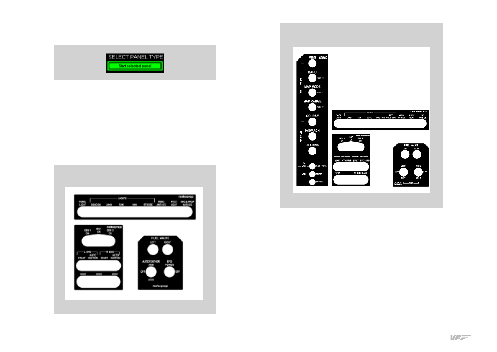
This instrument panel is designed to operate and display instruments
for both single-engine and twin-engine planes, and for the three en-
gine types: PISTON, TURBOFAN and TURBOPROP. In the next picture
you can see that some aircraft already have their own custom panel as
C-, Mooney, B-, etc ... but there are customizable panels called
"GENERIC" for other aircraft.
The planes best suited to the panel are just the planes that MFS/PD or
X-Plane incorporates by default.
Some planes from PD CARENADO had been tested, and that have
shown good results.
Boing option is not compatible with X-Plane it will only work with MFS/
PD Software.
Above you can see the panel has types of "GENERIC", on each of them
you can choose the full scale of the speedometer "Airspeed Range" and
type of instrument indication of direction "Directional Indicator".
To select the panel according the plane you want to fly, you have to do
two tasks:
• Select the indicators panel.
• Select the labels for the switches and rotaries of the panel.
Select the indicators panel:
The panel incorporates a ” touch-screen, so you must manage it with
your finger. Follow these steps:
• Press on the label that correspond to the plane you want to fly
in MFS / PD / X-Plane, (if there isn’t a customized label for that
plane, select a GENERIC label according to the engine type of
the plane (e.g. if the plane selected on MFS/PD is “Beechcraft
King Air A you must select the GENERIC “TURBO PROP-twin
engine in the panel”):
• If you have chosen a GENERIC panel, automatically a new
“Generic Panel OPTIONS” will open were you can select your
preferences:
o “Airspeed Range”
o “Directional indicator”.
4. SELECTION OF PANEL
TYPE (ACCORDING
TO PLANE)

84. SELECTION OF PANEL TYPE (ACCORDING TO PLANE) - USER’S MANUAL SOLO AIRLINER-RS
• Push on above centered label “Start Selected Panel” now
highlighted in Green.
Automatically the panel will show the gauges and indicators.
Select the labels for the switches and rotaries of the panel:
According the SOLO is a multifunction panel, a lot of switches change
its function depending if the gauges&indicators panel selected is for
piston, turboprop, or turbofan. The panel incorporates some magnetic
labels that you must place in the suitable zone to change the designa-
tion of each switch and rotary. The default designation of the switches
and rotaries (without magnetic labels) is for piston engines.
Magnetic Labels pack for turboprop engines:
Magnetic labels pack for turbofan (Boeing-737) engines:

9
5. ENGINE STARTING - USER’S MANUAL SOLO AIRLINER-RS
The following procedures are indicated by VirtualFly to start the plane
as simply as possible, never take these procedures for training or for
real aviation.
.. STARTING & STOP PISTON ENGINES (USING MFS / PD)
Starting piston engines (using MFS / PD)
. Pull on the PARKING BRAKE.
. Move the MIXTURE handle to RICH.
. Move the PROP RPM handle to HIGH.
. Move the POWER handle to DEC.
. Switch on the BAT.
. Switch on the MAGNETO L ENG “L” and “R”.
. Push on the red “START” left push-button to start the engine.
. Once the left engine is running, switch on the left LALT to charge the
battery.
. Switch on M. AVIONICS.
This procedure has started the single engine if it is a single-engine
airplane or the left engine if it is a twin-engine plane, in the latter case do
the indications , , to start the right engine.
Stop piston engines (using MFS / PD)
. Pull on the PARKING BRAKE.
. Move the MIXTURE handle to CUTOFF.
. Switch o the M. AVIONICS.
. Switch o the alternator/s ALT.
. Switch o the MAGNETO/S.
. Switch o the BAT.
5. ENGINE STARTING
Starting piston engines
Stop piston engines

10 5. ENGINE STARTING - USER’S MANUAL SOLO AIRLINER-RS
.. START & STOP PISTON ENGINES (USING X-PLANE)
Refer to the aircraft manual found in: <X-Plane Installation Folder>/
Aircraft/<The Aircraft Folder>. In the aircraft manual search for the
“Checklists” section. You will find detailed instructions for starting and
stopping the engines.

11
5. ENGINE STARTING - USER’S MANUAL SOLO AIRLINER-RS
.. STARTING & STOP TURBOPROP ENGINES (USING MFS / PD)
Starting turboprop engines (using MFS / PD)
. Pull on the PARKING BRAKE
. Move the MIXTURE handle to RICH
. Move the PROP RPM handle to HIGH
. Move the POWER handle to DEC
. Switch on the BAT
. Switch on the L ENG “START”
. The turbine will begin to rotate, after about - seconds activate
FUEL VALVE “LEFT”.
. Once the left engine is running switch o the L ENG “START”
. Switch on the GEN 1 to charge the batteries.
. Switch on M. AVIONICS
. Switch on EFIS POWER
This procedure has started the single engine if it is a single-engine
airplane or the left engine if it is a twin-engine plane, in the latter case
do the indications , , , to start the right engine.
IMPORTANT! Before activating GEN do not forget to disable
START, if don’t do that the generator will not charge the batteries.
Stop turboprop engines (using MFS / PD)
. Pull on the PARKING BRAKE
. Switch o the FUEL VALVE/S
. Move the MIXTURE handle to CUTOFF
. Switch o the M. AVIONICS
. Switch o the GEN/S
. Switch o the BAT
Starting turboprop engines
Stop turboprop engines

12 5. ENGINE STARTING - USER’S MANUAL SOLO AIRLINER-RS
.. START & STOP TURBOPROP ENGINES (USING X-PLANE)
Refer to the aircraft manual found in: <X-Plane Installation Folder>/
Aircraft/<The Aircraft Folder>. In the aircraft manual search for the
“Checklists” section. The switch INVERTER cannot be found in SOLO.
You will find detailed instructions for starting and stopping the engines.

13
5. ENGINE STARTING - USER’S MANUAL SOLO AIRLINER-RS
.. STARTING & STOP TURBOFAN (BOEING ) ENGINES (ONLY
MFS/PD)
Starting turbofan (Boeing ) engines (only MFS/PD)
In this type of engine RPM and PROP MIXTURE handles are not used,
however, the MIXTURE handle must be outside the CUTOFF area.
. Pull on the PARKING BRAKE.
. Move the POWER handle to DEC.
. Switch on the BAT.
. Switch on the L ENG “START”, the left turbine will begin to rotate.
. When the indicator N1 reaches the . value, switch on the FUEL
VALVE “LEFT”.
. Once the left engine is running switch o the L ENG “START”.
. Switch on the GEN 1 to charge the batteries.
. Switch on L ENG “HYD PUMP” to activate the hydraulic systems.
. Switch on M. AVIONICS.
This procedure has started the left engine, do the indications , , , ,
, to start the right engine.
IMPORTANT! Before activating GEN do not forget to disable
START, if don’t do that the generator will not charge the batteries
Stop turbofan engines (only MFS/PD)
. Pull on the PARKING BRAKE.
. Switch o the FUEL VALVES.
. Switch o the M. AVIONICS.
. Switch o the GEN.
. Switch o the HYD PUMP.
. Switch o the BAT.
Starting turbofan engines
Stop turbofan engines

14 6. SIMULATING THE BOEING 737 (ONLY MFS /P3D) - USER’S MANUAL SOLO AIRLINER-RS
6. SIMULATING
THE BOEING 737
(ONLY MFS/P3D)
First of all, tell that to run the panel Boeing you must to install the ser-
ver B- "aeroServer" in the MFS / PD computer. To buy that server
license, enter in the following link and follow the steps for the installation.
http://www.aerosoft.com.au/aerosoft_australia/home.html
The following link shows several tutorials where you can learn to get the
most out of this software:
http://www.aerosoft.com.au/aerosoft_australia/video.html
Even so, we are going to provide minimal information for you to generate
a flight plan through the FMC-CDU and fly it through the autopilot.
The screen showing the indicators, autopilot, EFIS selector and CDU is a
touch-screen so you can press any button or key with your finger, but all
numerical values are adjusted with some real rotary handle in the panel.
On the next page you will see a relationship between the rotary handle
and values that fit.
Also note that the most basic functions of the buttons on the autopilot
can be activated from the Radiostack, on the next page you will see a link
between Radiostack buttons and buttons on the autopilot.
IMPORTANT! Before selecting the B panel you must already
have the B- selected in the MFS/PD, should also have the
flight loaded with the plane on the ground, not to do so some
indicators will not work correctly.

15
6. SIMULATING THE BOEING 737 (ONLY MFS /P3D) - USER’S MANUAL SOLO AIRLINER-RS

16 6. SIMULATING THE BOEING 737 (ONLY MFS /P3D) - USER’S MANUAL SOLO AIRLINER-RS
A flight plan like bellow has to appear:
After the take-o, you can activate the AUTOPILOT by pressing “CMD”
key and then “LNAV” to follow the route.
Example introducing a flight plan
Here we show a simple example of how to enter a flight plan from "Los
Angeles, runway L" to "San Francisco":
Before beginning, place the plane in the 25L runway of the KLAX
“Los Angeles” Airport.
• Press on RTE key, it appears the RTE 1/2 screen like the figure.
• Type KLAX and place it in ORIGIN “L”.
• Type L and place it in RUNWAY “L”.
• Type KSFO and place it in DEST “R”.
• Press the “NEXT PAGE” key, it appears the RTE 2/2 screen like the
figure bellow-right.
• Type MERMA and place it in TO “R”.
• Type SFO and place it in TO “R”.
• Type V and replace DIRECT “L”.
• Press ACTIVATE “R”.
• Press on “EXEC” key.

17
7. RADIOSTACK PANEL - USER’S MANUAL SOLO AIRLINER-RS
It is an application with general and commercial aviation radio equip-
ment, for learning in flight schools or for the use of simulators and which
is updated with values sent by MFS / PD / X-Plane (hereafter referred
to as MFS / PD/ X-Plane). It incorporates six virtually simulated Bendix®/
King brand instruments.
The idea is that these instruments are the same as the real ones, with full
functions or as close as possible, but due to limitations of FS, they are
not completely operable.
Some options may dier a bit depending on the simulation software you
are using (MFS/PD or X-Plane), these dierences are detailed in the
following instructions.
The majority of the instruments work directly with MFS / PD / X-Plane.
However, we must point out that some equipment includes more fea-
tures or display information or that some instruments operate indepen-
dently in the SOLO.
7. RADIOSTACK PANEL

18 7. RADIOSTACK PANEL - USER’S MANUAL SOLO AIRLINER-RS
.. AUDIO PANEL
Use the COM1, COM2 or BOTH buttons on the audio panel to choose
the radio frequencies you want to transmit and receive. To choose a
single radio to tune, transmit and receive, just activate the COM
or COM buttons. If you select BOTH buttons, it will transmit in the
previously selected radio, but you will hear both radio frequencies. This
is especially useful during an approach, since you probably do not want
to stop hearing the controller to hear the ATIS (if you did so, you would
lose trac calls). The NAV, NAV, MRK, DME, and ADF buttons are
used to listen and identify the Morse code associated with the station.
.. AUTO-PILOT
This autopilot does not do anything by itself; it only sends and receives
orders from the simulator. MFS/PD or X-Plane controls the entire
operation.
Some button functions may dier depending if you are using MFS/PD
or X-Plane, these dierences are detailed in the following definitions.
Definition of buttons
• AP: activates or deactivates the autopilot. The acronym AP appears
on the notification screen when active.
• HDG: Heading mode (direction). Follow the heading indicator selec-
ted in the directional-gyro or HSI.
• NAV: Navigation Mode (VOR). NAV arm mode to intercept and track
the radial selected on the VOR .
• APR: Approach Mode (LOC or ILS). Arms the APR mode to intercept
and capture the localizer and the glideslope (if there is one). If HDG is
active, it will be replaced by APR when the localizer is captured and if
ALT is active, it will be replaced by GS.
• REV: Back course LOC. Arms the back localizer to execute an out-
bound heading and proceed to ordinary ILS procedure.
• ALT:
• MFS/PD: Altitude Hold. Arms ALT mode. If the AP is connected,
the aircraft will ascend or descend to the desired altitude, which
is always displayed on-screen at the vertical speed (VS) selected.

19
7. RADIOSTACK PANEL - USER’S MANUAL SOLO AIRLINER-RS
The VS can be modified at any time with the UP and DN buttons.
• X-Plane: Altitude Hold. If the AP is connected, the aircraft will
maintain the current altitude
• UP and DN: Used to change the vertical speed. Increase or decrease
by ft., respectively, each time they are pressed.
• ALT SEL (Only MFD/PD) Use to change the desired altitude. By pres-
sing this dial like a push-button, you can choose ft. or ft.
increments.
Display indications:
Armed modes for roll: Can be NAV, APR, REV or GS. (Although the latter
belongs to pitch). Armed mode shows a vertical ARM tag to their right.
Active roll modes: Can be ROL, HDG, NAV, APR or REV:
• ROL: Active level wings.
• HDG: Active heading mode.
• NAV: Radial NAV intercepted and following it.
• APR: ILS localizer capture.
• REV: ILS localizer back course capture.
Indicators:
• AP: The master AP switch is connected.
Armed mode for pitch Can be ALT.
MFS/PD: When the ALT mode is connected, it initially remains armed
until it is reached.
X-Plane: Cannot be armed, the altitude remains constant when ALT is
connected.
Active pitch modes: Can be PIT, VS, ALT or GS.
• PIT: Pitch is maintained (occurs when the AP is connected with no
other mode active).
• VS: The altitude mode is armed, but is going up and down to VS selected.
• ALT: Altitude has been reached and maintained.
• GS: the glideslope has been captured.
Alert: This label is illuminated when the aircraft's altitude is between
ft. and ft. of reaching the desired altitude. It always hap-
pens, even when the AP is disconnected or ALT is not selected, as
a visual help.
.. COMMUNICATION AND NAVIGATION
Definition of buttons
Dial: Rotate to change the decimal of the frequency in increments of
"." or rotate keeping the dial pressed to change the integers in in-
crements of ".".
<> Push-button: Use to exchange USE and STBY frequencies.

20 7. RADIOSTACK PANEL - USER’S MANUAL SOLO AIRLINER-RS
.. DME, ADF AND TRANSPONDER
DME
Due to MFS / PD / X-Plane limitations, it always works in remote mode
(RMT), which means it is always associated with NAV or NAV; you
can't select an independent frequency. If no signal is received from the
DME, the display shows dashes.
Definition of buttons
Move the selector – to find out the distance (nautical miles), Speed
(Knots), Time (Minutes) up to the station selected in NAV or NAV.
ADF
Definition of buttons
Dial: Rotate to change the frequency in increments of "." or rota-
te keeping the dial pressed to change the frequency in increments of
".".
<> Button: Use to change between USE and STBY frequencies.
TRANSPONDER XPDR
Definition of buttons
Select the digit to be modified: Press the dial as a push-button to chan-
ge the digit you want to modify (the selected digit is displayed with a
small number).
Modify the value of the digits: Turn the dial, the value varies between
and .
Function selector: Rotate and press the dial at the same time, the
functions varies between OFF, STBY, ON, ALT.
Table of contents
Other Aircatglobal Avionic Display manuals
Popular Avionic Display manuals by other brands

Ryan TCAD
Ryan TCAD 9900 Pilot's handbook

Garmin
Garmin Approach G5 - GPS-Enabled Golf Handheld Maintenance manual

II Morrow
II Morrow Apollo GX 50 user guide

GRT Avionics
GRT Avionics HXr installation manual

J.P. Instruments
J.P. Instruments EDM-700 pilot's guide

Levil Aviation
Levil Aviation iLevil 3 SW instruction manual