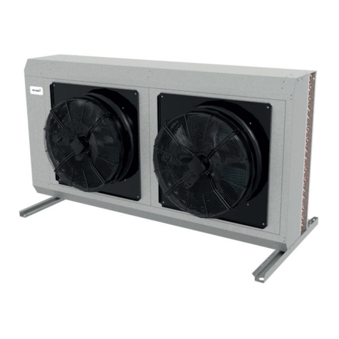
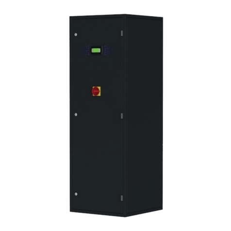
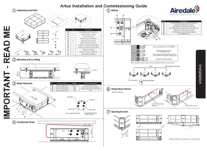
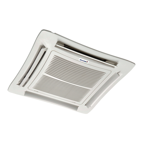
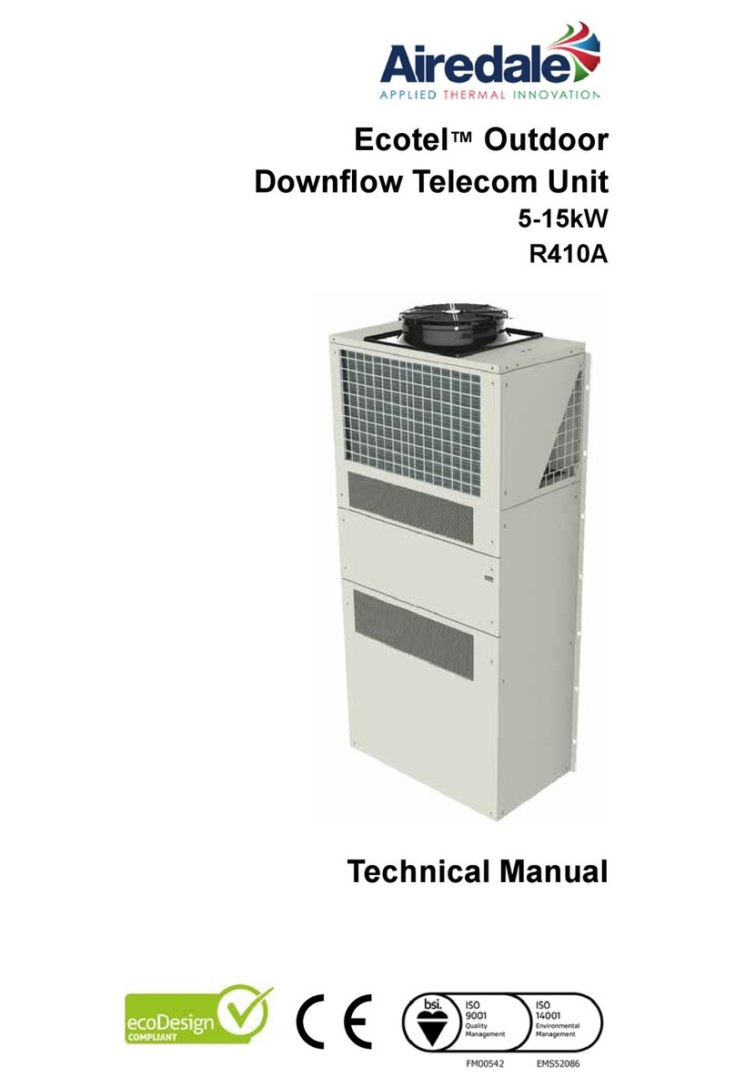
AIREDALE ET05D User manual

EMS52086FM00542
Technical Manual
Ecotel™Outdoor
Free Cooling Unit
5-15kW
ET05D
ET10D
ET15D

Ecotel™ FreeCool Telecoms
2
Ecotel™ FreeCool 5-15kW Technical Manual 9368648 v1.6.0 12_2016
Customer Services
Warranty, Commissioning & Maintenance
As standard, Airedale guarantees all non consumable parts only for a period of 12 months, variations tailored to suit
product and application are also available; please contact Airedale for full terms and details.
To further protect your investment in Airedale products, Airedale can provide full commissioning services,
comprehensive maintenance packages and service cover 24 hours a day, 365 days a year (UK mainland).
For a free quotation contact Airedale or your local Sales Engineer.
All Airedale products are designed in accordance with EU Directives regarding prevention of build up of water,
associated with the risk of contaminants such as legionella.
For effective prevention of such risk it is necessary that the equipment is maintained in accordance with Airedale
recommendations.
In addition to commissioning, a 24 hour, 7 days a week on-call service is available throughout the year to UK mainland
sites. This service will enable customers to contact a duty engineer outside normal working hours and receive
assistance over the telephone. The duty engineer can, if necessary, attend site, usually within 24 hours or less.
Full details will be forwarded on acceptance of the maintenance agreement.
Warranty cover is not a substitute for maintenance. Warranty cover is conditional to maintenance
being carried out in accordance with the recommendations provided during the warranty period.
Failure to have the maintenance procedures carried out will invalidate the warranty and any
liabilities by Airedale International Air Conditioning Ltd.
Spares
A spares list for 1, 3 and 5 years will be supplied with every unit and is also available from our Spares department on
request.
Training
As well as our comprehensive range of products, Airedale offers a modular range of Refrigeration and Air Conditioning
Training courses, for further information please contact Airedale.
Customer Services
For information, visit us at our web site: www.airedale.com
Airedale Ltd endeavours to ensure that the information in this document is correct and fairly stated, but none of the
statements are to be relied upon as a statement or representation of fact. Airedale Ltd does not accept liability for any
error or omission, or for any reliance placed on the information contained in this document. The development of Airedale
products and services is continuous and the information in this document may not be up to date. It is important to check
the current position with Airedale Ltd at the address stated. This document is not part of a contract or licence unless
expressly agreed. No part of this document may be reproduced or transmitted in any form or by any means, electronic
or mechanical, including photocopying, recording, or information storage and retrieval systems, for any purpose other
than the purchaser’s personal use, without the express written permission of Airedale Ltd.
©2016 Airedale International Air Conditioning Limited. All rights reserved. Printed in the UK.
CAUTION
SafeCool™
Health and Safety
IMPORTANT
The information contained in this manual is critical to the correct operation and maintenance of the unit and should be
read by all persons responsible for the installation, commissioning and maintenance of this Airedale unit.
Safety
The equipment has been designed and manufactured to meet international safety standards but, like any mechanical/
electrical equipment, care must be taken if you are to obtain the best results.
When working with any air conditioning units ensure that the electrical isolator is switched off prior
to servicing or repair work and that there is no power to any part of the equipment. Also ensure
that there are no other power feeds to the unit such as fi re alarm circuits, BMS circuits etc.
Electrical installation commissioning and maintenance work on this equipment should be
undertaken by competent and trained personnel in accordance with local relevant standards and
codes of practice.
A full hazard data sheet in accordance with COSHH regulations is available should this be required.
Personal Protective Equipment
Airedale recommends that personal protective equipment is used whilst installing, maintaining and commissioning
equipment.
Manual Handling
Some operations when servicing or maintaining the unit may require additional assistance with regard to manual
handling. This requirement is down to the discretion of the engineer.
Remember do not perform a lift that exceeds your ability.
CAUTION
Refrigerant Warning
The Airedale unit uses R410A refrigerant which requires careful attention to proper storage and handling procedures.
Use only manifold gauge sets designed for use with R410A refrigerant. Use only refrigerant recovery units and cylinders
designed for high pressure refrigerants.
R410A must only be charged in the liquid state to ensure correct blend makeup.
The refrigerant must be stored in a clean, dry area away from sunlight.
The refrigerant must never be stored above 50°C.
Maximum and Minimum Operation Temperature (Ts) and Pressure (Ps)
Operating Temperature (Ts), Ts = Min -20°C to Max 120°C *
Maximum Operating Pressure (Ps) Ps = High Side 40.7 Barg
*Based upon the maximum machine running temperatures.
Global Warming Potential
The R410A refrigerant has a GWP of 1980 (based on EN378-1:2008+A2:2012, 100 year life)
Environmental Considerations
Units with supply water temperatures below +5°C
• Glycol is recommended when a supply water temperature of +5°C or below is required or when static water can
be exposed to freezing temperatures.
Units subject to ambient temperatures lower than 0°C
• Glycol of an appropriate concentration (1) must be used within the system to ensure adequate freeze protection.
Please ensure that the concentration is capable of protection to at least 3°C lower than ambient.
• Water/glycol solution should be constantly circulated through all waterside pipework and coils to avoid static water
from freezing.
• Ensure that pumps are started and running even during shut down periods, when the ambient is within 3°C of the
solution freeze point (1) (i.e. if the solution freezes at 0°C, the pump must be operating at 3°C ambient).
• Additional trace heating is provided for interconnecting pipework.
(1) Refer to your glycol supplier for details.
Environmental Policy
It is our policy to:
• Take a proactive approach to resolve environmental issues and ensure compliance with regulatory requirements.
• Train personnel in sound environmental practices.
• Pursue opportunities to conserve resources, prevent pollution and eliminate waste.
• Manufacture products in a responsible manner with minimum impact on the environment.
• Reduce our use of chemicals and minimise their release to the environment.
• Measure, control and verify environmental performance through internal and external audits.
• Continually improve our environmental performance.
CE Directive
Airedale certify that the equipment detailed in this manual conforms with the following EC Directives:
Electromagnetic Compatibility Directive (EMC) 2014/30/EU
Low Voltage Directive (LVD) 2014/35/EU
Machinery Directive (MD) 89/392/EEC version 2006/42/EC
To comply with these directives appropriate national & harmonised standards have been applied. These are listed on the
Declaration of Conformity, supplied with each product.
Telecoms Ecotel™ FreeCool
3
Ecotel™ FreeCool 5-15kW Technical Manual 9368648 v1.6.0 12_2016
Customer Services
Warranty, Commissioning & Maintenance
As standard, Airedale guarantees all non consumable parts only for a period of 12 months, variations tailored to suit
product and application are also available; please contact Airedale for full terms and details.
To further protect your investment in Airedale products, Airedale can provide full commissioning services,
comprehensive maintenance packages and service cover 24 hours a day, 365 days a year (UK mainland).
For a free quotation contact Airedale or your local Sales Engineer.
All Airedale products are designed in accordance with EU Directives regarding prevention of build up of water,
associated with the risk of contaminants such as legionella.
For effective prevention of such risk it is necessary that the equipment is maintained in accordance with Airedale
recommendations.
In addition to commissioning, a 24 hour, 7 days a week on-call service is available throughout the year to UK mainland
sites. This service will enable customers to contact a duty engineer outside normal working hours and receive
assistance over the telephone. The duty engineer can, if necessary, attend site, usually within 24 hours or less.
Full details will be forwarded on acceptance of the maintenance agreement.
Warranty cover is not a substitute for maintenance. Warranty cover is conditional to maintenance
being carried out in accordance with the recommendations provided during the warranty period.
Failure to have the maintenance procedures carried out will invalidate the warranty and any
liabilities by Airedale International Air Conditioning Ltd.
Spares
A spares list for 1, 3 and 5 years will be supplied with every unit and is also available from our Spares department on
request.
Training
As well as our comprehensive range of products, Airedale offers a modular range of Refrigeration and Air Conditioning
Training courses, for further information please contact Airedale.
Customer Services
For information, visit us at our web site: www.airedale.com
Airedale Ltd endeavours to ensure that the information in this document is correct and fairly stated, but none of the
statements are to be relied upon as a statement or representation of fact. Airedale Ltd does not accept liability for any
error or omission, or for any reliance placed on the information contained in this document. The development of Airedale
products and services is continuous and the information in this document may not be up to date. It is important to check
the current position with Airedale Ltd at the address stated. This document is not part of a contract or licence unless
expressly agreed. No part of this document may be reproduced or transmitted in any form or by any means, electronic
or mechanical, including photocopying, recording, or information storage and retrieval systems, for any purpose other
than the purchaser’s personal use, without the express written permission of Airedale Ltd.
©2016 Airedale International Air Conditioning Limited. All rights reserved. Printed in the UK.
CAUTION
SafeCool™
Health and Safety
IMPORTANT
The information contained in this manual is critical to the correct operation and maintenance of the unit and should be
read by all persons responsible for the installation, commissioning and maintenance of this Airedale unit.
Safety
The equipment has been designed and manufactured to meet international safety standards but, like any mechanical/
electrical equipment, care must be taken if you are to obtain the best results.
When working with any air conditioning units ensure that the electrical isolator is switched off prior
to servicing or repair work and that there is no power to any part of the equipment. Also ensure
that there are no other power feeds to the unit such as fi re alarm circuits, BMS circuits etc.
Electrical installation commissioning and maintenance work on this equipment should be
undertaken by competent and trained personnel in accordance with local relevant standards and
codes of practice.
A full hazard data sheet in accordance with COSHH regulations is available should this be required.
Personal Protective Equipment
Airedale recommends that personal protective equipment is used whilst installing, maintaining and commissioning
equipment.
Manual Handling
Some operations when servicing or maintaining the unit may require additional assistance with regard to manual
handling. This requirement is down to the discretion of the engineer.
Remember do not perform a lift that exceeds your ability.
CAUTION
Refrigerant Warning
The Airedale unit uses R410A refrigerant which requires careful attention to proper storage and handling procedures.
Use only manifold gauge sets designed for use with R410A refrigerant. Use only refrigerant recovery units and cylinders
designed for high pressure refrigerants.
R410A must only be charged in the liquid state to ensure correct blend makeup.
The refrigerant must be stored in a clean, dry area away from sunlight.
The refrigerant must never be stored above 50°C.
Maximum and Minimum Operation Temperature (Ts) and Pressure (Ps)
Operating Temperature (Ts), Ts = Min -20°C to Max 120°C *
Maximum Operating Pressure (Ps) Ps = High Side 40.7 Barg
*Based upon the maximum machine running temperatures.
Global Warming Potential
The R410A refrigerant has a GWP of 1980 (based on EN378-1:2008+A2:2012, 100 year life)
Environmental Considerations
Units with supply water temperatures below +5°C
• Glycol is recommended when a supply water temperature of +5°C or below is required or when static water can
be exposed to freezing temperatures.
Units subject to ambient temperatures lower than 0°C
• Glycol of an appropriate concentration (1) must be used within the system to ensure adequate freeze protection.
Please ensure that the concentration is capable of protection to at least 3°C lower than ambient.
• Water/glycol solution should be constantly circulated through all waterside pipework and coils to avoid static water
from freezing.
• Ensure that pumps are started and running even during shut down periods, when the ambient is within 3°C of the
solution freeze point (1) (i.e. if the solution freezes at 0°C, the pump must be operating at 3°C ambient).
• Additional trace heating is provided for interconnecting pipework.
(1) Refer to your glycol supplier for details.
Environmental Policy
It is our policy to:
• Take a proactive approach to resolve environmental issues and ensure compliance with regulatory requirements.
• Train personnel in sound environmental practices.
• Pursue opportunities to conserve resources, prevent pollution and eliminate waste.
• Manufacture products in a responsible manner with minimum impact on the environment.
• Reduce our use of chemicals and minimise their release to the environment.
• Measure, control and verify environmental performance through internal and external audits.
• Continually improve our environmental performance.
CE Directive
Airedale certify that the equipment detailed in this manual conforms with the following EC Directives:
Electromagnetic Compatibility Directive (EMC) 2014/30/EU
Low Voltage Directive (LVD) 2014/35/EU
Machinery Directive (MD) 89/392/EEC version 2006/42/EC
To comply with these directives appropriate national & harmonised standards have been applied. These are listed on the
Declaration of Conformity, supplied with each product.
Ecotel™ FreeCool Telecoms
4
Ecotel™ FreeCool 5-15kW Technical Manual 9368648 v1.6.0 12_2016
Contents
Specier’s Guide 5
Nomenclature 5
Introduction 5
Construction 5
Unit Overview 6
Front View 6
Rear View 6
Case Sizes 7
Airow Components 8
Electrical Components 10
Controls 12
External 16
Product Operation 17
Free Cooling Mode 17
Installation 18
General 18
Positioning 19
Dimensions 20
Incoming Services 24
Exhaust Installation 25
Technical Data 26
ET05D 26
ET10D 30
ET15D 34
Performance Data 38
Sound Data 40
Installation Wiring 42
pLAN Termination 44
Maintenance 45
General Inspections 46
Fan Removal 46
Filter Removal 47
Electrical Inspections 48
Controls 49
Troubleshooting 50
Alarms 51
Alarm Menu Display 51
After Sales 53
Warranty 53

Telecoms Ecotel™ FreeCool
5
Ecotel™ FreeCool 5-15kW Technical Manual 9368648 v1.6.0 12_2016
Specier’s Guide
Nomenclature
Introduction
The Ecotel FreeCool is a self contained packaged outdoor unit designed to cool areas such as outdoor cabins, shelters
and telecom base stations. The unit range is available with 5kW, 10kW and 15kW and offers the following features:
• Standalone fresh air free cooling ability
• Efcient EC centrifugal fan
• -48VDC unit power supply
Construction
There shall be 2 case sizes in the Ecotel Free Cooling Only unit product range; each case in the range shares a
common design.
The case shall be constructed from sheet metal. The front panels shall be xed with tamper proof xings and is
removable to allow access to the centrifugal fan, lter panel, and control panel. The sheet metal as standard shall be
painted RAL7038 (Agate Grey) or RAL 6014 (Yellow Olive), but can be available in other colours as per optional extra.
A backward-curved plug fan shall be mounted horizontally at the top of the unit and is accessible from the front for easy
serviceability. The unit shall be supplied loose with a pressure relief damper as standard to exhaust the warm air out of
the cabin when the unit is operating. This requires no control from the unit and works via pressure in the cabin space
created by the unit forcing the damper blades open.
example: ET 10 D - F A 1 - 7
ET EcoTel Unit
10 Nominal cooling capacity in kW
DDownow (Recommended Installation)*
-Separator
FFree Cooling
SStandard Controls
AAdvanced Controls
0AC Unit Power Supply
1-48V DC Unit Power Supply
-Separator
7230V/1~ +N/50Hz
8220V/1~ +N/60Hz
9220V/2~ no neutral/60Hz
*Denominates airow delivered to the lower portion of the room
Not applicable when DC power supply is selected (refer to Voltage Options for further information)
Introduction

Ecotel™ FreeCool Telecoms
6
Ecotel™ FreeCool 5-15kW Technical Manual 9368648 v1.6.0 12_2016
Removable Centrifugal EC Fan
Control Panel
G4 Air Filter
Removable Front Panel with Door Seal
Mounting Bracket
Tamper Proof
Fixings
Unit Overview
Front View
Rear View
Introduction

Telecoms Ecotel™ FreeCool
7
Ecotel™ FreeCool 5-15kW Technical Manual 9368648 v1.6.0 12_2016
Case Sizes
The Ecotel range shall have a total of 2 case sizes. 5kW & 10kW utilise the same case dimensions, the 15kW has
a larger case size to house a larger fan.
Case Size ET05D ET10D ET15D
Width (mm) 570 570 730
Height (mm) 740 740 850
Depth (mm) 560 560 730
Cooling Capacity* (kW) 510 15
Design Air Volume (m3/s) 0.41 0.83 1.24
Number of Fans 111
*At 10°C Delta T
Introduction

Ecotel™ FreeCool Telecoms
8
Ecotel™ FreeCool 5-15kW Technical Manual 9368648 v1.6.0 12_2016
Airow Components
System Conguration
Features ET05D ET10D ET15D
Airow
Backward Curved EC Fan ●●●
-48VDC Centrifugal Fan ○○○
G4 Filtration ●●●
M5 Filtration ○○○
Air Flow Switch ○○○
Filter Change ○○○
Fire Rated Dampers ○○○
Double Deection Grille ●●●
Pressure Relief Exhaust Dampers ●●●
Actuated Exhaust Damper* ○○○
Ambient Weather Louvres ●●●
● Standard Features ○ Optional Features – Feature Not Available
*Optional with Advanced Controls Unit
Fan & Motor Assembly
Backward curved impellers, direct drive centrifugal fan assemblies shall be used with integral EC motors. They shall be
dynamically balanced for quiet operation.
Fan speed and air ow shall be controlled by the use of a voltage controller which shall maintain optimised performance
and reduce energy consumption.
Designed for high corrosion resistance, the impellers shall be composite plastic with a galvanised rotor.
G4 Filtration
The unit shall be tted with pleated disposable panel lters in a rigid metal frame. Conform to BS EN 779-G4.
Access and removal from unit front.
As standard the microprocessor shall provide an alarm following a pre set run time limit being exceeded.
High Efciency Filters
45mm, pleated disposable panel lters conforming to BS EN 779-M5 shall be provided. To maintain design pressure fan
selection may alter with high efciency lters. Access and removal from unit front. As standard the microprocessor shall
provide an alarm following a pre set run time limit being exceeded.
Air Flow Switch
An adjustable differential pressure switch shall activate a visual alarm at the status panel and switch the unit off in the
event of a fan or motor failure.
Filter Change
A lter change software timer shall be included to record the time since the lter was changed and give an alarm if the
time is exceeded. This must be manually reset when the lters are changed.
Spring Return Air Damper Actuator Fire Rated Damper
EC centrifugal fan
Introduction

Telecoms Ecotel™ FreeCool
9
Ecotel™ FreeCool 5-15kW Technical Manual 9368648 v1.6.0 12_2016
Electronically Commutated (EC) Fan Motor
EC motors incorporate integrated electronics to convert AC power to DC for efcient and accurate speed control and are
adjustable via the microprocessor display keypad.
The fans offer maximum air ow performance while keeping sound levels to a minimum.
It gives the exibility of connecting to AC mains with the efciency and simple speed control of a DC motor. The EC
fan offers signicant power reduction in comparison with equivalent AC fan at both full and modulated fan speeds. The
inbuilt EC fan control module allows for fan speed modulation from 15-100%. A standard AC fans modulating range is
typically 40 -100% of full fan speed.
Standard voltage regulated (VR) fan speed controllers offer a linear response. The following illustration shows a
comparison of the typical power input required by each method.
Input Power
Airflow
EC (Electronically Commutated) Fan Speed Control
Regulated (VR) Fan Speed Control
Key
Fire Rated Dampers
Optional curtain type re dampers shall be tted to supply and exhaust, with galvanised steel construction as standard.
Fire tested to BS EN 1366-2:1999 and classied to BS EN 13501-3:2005 + A1:2009.
Double Deection Grille
The unit shall have a double deection grille to deect air inside the cabin to high priority equipment and ensure even air
distribution.
Pressure Relief Exhaust Damper
A pressure relief exhaust damper shall be tted at the exhaust air of the unit, to regulate cooling performance. This shall
open or close depending on cabin pressure.
Actuated Exhaust Damper
An optional actuated exhaust damper shall be tted at the exhaust air of the unit, to regulate cooling performance. The
damper shall be tted with a spring return actuator.
Introduction

Ecotel™ FreeCool Telecoms
10
Ecotel™ FreeCool 5-15kW Technical Manual 9368648 v1.6.0 12_2016
System Conguration
Features ET05D ET10D ET15D
Electrical
Mains Isolator ●●●
Energy Manager* ○○○
230V/1PH + N/50Hz ●●●
220V/1PH + N/60Hz ○○○
220V/2PH No Neutral/60Hz ○○○
-48VDC Unit Power Supply ○○○
● Standard Features ○ Optional Features – Feature Not Available
*Does not communicate with IR33 on a unit congured for Standard Controls
Electrical Components
Transformer
Air Flow Switch
pCO5 built in controller
MCB
Thermostat
Advanced Control Panel
Electrical
The control panel shall contain the transformer, sub circuit protection, volt free contacts for a common alarm, mains
and sensor terminals. The panel shall be situated within the unit and can be opened to allow for essential maintenance
of other components within the unit. The electrical control panels shall be wired to the latest European standards and
codes of practice.
Energy Manager
Analysis of system energy consumption shall be monitored via a dedicated LCD display. Unit parameters shall be
adjusted via the unit microprocessor control to affect energy usage in line with the system need. To communicate with
the energy manager option on a standard controls unit the user will have to connect direct to the Energy Manager via
Modbus.
Introduction

Telecoms Ecotel™ FreeCool
11
Ecotel™ FreeCool 5-15kW Technical Manual 9368648 v1.6.0 12_2016
Voltage Options
The image below illustrates the voltage options for different unit congurations. Where -48VDC is used, the -7/-8/-9
sufx should be disregarded.
Local Isolator (Typical Placement)
LI
N
E
230V 1PH (N) 50HZ (-7)
LI
N
E
220V 1PH N 60HZ (-8)
LI
L2
E
220V 2PH 60HZ (-9)
+VE (GND)
-VE (-48V)
-48VDC 2 WIRE
POSITIVE EARTHED
(-7/-8/-9)
FS0/FA0 units FS1/FA1 units
AC Options DC Option
Mains Isolator
To comply with BS EN 6024-1:2006 Safety of Machinery – Electrical Equipment Machines, each unit should have
an accompanying isolator (switch disconnecting device). The supply disconnecting device shall isolate the electrical
equipment of the telecoms unit from the electrical supply when required.
The isolator shall be easily accessible and mounted between 0.6m and 1.9 above the service level. An upper limit of
1.7m is recommended.
Introduction
Isolator

Ecotel™ FreeCool Telecoms
12
Ecotel™ FreeCool 5-15kW Technical Manual 9368648 v1.6.0 12_2016
System Conguration
Features ET05D ET10D ET15D
Controls
IR33 inbuilt microcontroller ●●●
pCO5 compact microcontroller* ●●●
Remote Display* ○ ○ ○
LED Alarm Indicator* ○ ○ ○
BMS Interface Cards* ○ ○ ○
Humidity Monitoring* ○○○
Advanced Cabin Temperature Control** ○ ○ ○
● Standard Features ○ Optional Features – Feature Not Available
*option only available with Advanced Controls Unit **up to 4 extra sensors
Controls
pCO5 Compact Controller IR33 Controller
IR33 Inbuilt Microcontroller
The IR33 is a basic, compact and cost effective parametric controller. Preloaded with a standard software strategy,
it allows limited programming through dening various options and parameters that give it the ability to perform a range
of common operating modes.
The semi-programmable nature of the IR33 makes it an ideal quick solution for simple applications where basic PID
control is required.
Introduction

Telecoms Ecotel™ FreeCool
13
Ecotel™ FreeCool 5-15kW Technical Manual 9368648 v1.6.0 12_2016
The control system integrity shall be maintained by restricting access with a password PIN
number. To change the PIN , please contact Airedale at time of order with the preferred 4 digit
number.
IMPORTANT
PCO5 Compact Microcontroller
The units shall be supplied with a European ROHS Directive 2002/95/EC compatible microprocessor controller.
The microprocessor controller shall offer powerful analogue and digital control to meet a wide range of monitoring and
control features including a real time clock and industry standard communication port and network connections.
All the boards feature a 16 bit microprocessor, and consequently the calculation power and operation processing speed
have been signicantly increased. A visual alarm and the facility to adjust and display control settings by local operator
for information and control shall also be featured.
The pCO5 Compact is designed for use in space sensitive applications. and is fully
programmable.
Fully programmable controller.
• 10 inputs (8 analogue, 2 digital)
• 9 outputs (2 analogue, 7 digital)
• Programmable modbus interface
Display/Keypad
The display keypad shall feature a simple array of keys to navigate through the in built menus.
With an 8 x 22 character (132 x 64 pixel) screen size, back lit in white for improved contrast, the larger screen shall
provide for user friendly viewing and easy status recognition by displaying a combination of text and icons.
The default screen shall show the unit status and room condition (°C) without the need for interrogation and an easy to
navigate menu structure for further interrogation and adjustment shall be provided.
LCD Unit Display
12
4
3
6
5
No. Description
1Date
2 Time
3Cabin Temperature (max./avg.)
4Fan Speed & Heating Status
5Additional Information (ambient temp./setpoint/humidity)
6 Unit Status
Introduction

Ecotel™ FreeCool Telecoms
14
Ecotel™ FreeCool 5-15kW Technical Manual 9368648 v1.6.0 12_2016
Icon Name/Description Used To Represent
Ticked box Yes, enabled, active, on etc.
Unticked box No, disabled, inactive, off etc.
Setpoint Setpoint
Alarm Alarm, off by alarm
Unit Off Unit off by external factor (i.e. PLAN, digital input)
Unit On/Off Off by display
Unit Standby Standby – on but no action required
Unit Sleep Unit off by timer
Service Manual mode, overrides, attend mode
Fan Fans, freecooling mode
Display Icons - PC05
To ensure the software is easy to read at a glance and to make translations easier, the Ecotel user interface is largely
graphical, containing a large number of icons to represent different modes, actions or components. The following table is
a glossary of icons to use as a reference:
Introduction

Telecoms Ecotel™ FreeCool
15
Ecotel™ FreeCool 5-15kW Technical Manual 9368648 v1.6.0 12_2016
LED Alarm Indicator
Similar to the full Ecotel product, the freecooling only unit shall be tted with an alarm indicator as an option. Due to the
simplicity of the freecooling only unit, the alarm indicator for this product is a tri-colour LED mounted to the outer case.
The following table shows what colour the LED illuminates to indicate different operating states.
LED Colour Unit Status
OFF LED or Power Fault
GREEN Unit OK
YELLOW Non Critical/General Alarm
RED Critical Alarm
BMS Interface Cards
BMS Interface Card controlled units can be interfaced with most BMS. These shall be factory tted, please contact
Airedale for further information.
A wide range of protocols shall be accommodated through the use of interface devices. Available as a standard option
are: ModBus/Jbus, and Carel. For interfaces such as SNMP, LonWorks, Metasys and BACnet, please contact Airedale.
Also available shall be Airedale’s own supervisory plug-in BMS card pCOWEB, based on Ethernet TCP/IP secure
technology with SNMP features. It shall require no proprietary cabling or monitoring software and be supplied pre-
programmed with an IP address for ease of set up. Cables to the BMS to be supplied by others.
Temperature Control
A temperature sensor shall be mounted in the inlet of the unit to sense the outdoor air condition. The temperature sensor
shall be an NTC type thermistor with an accuracy of not less than +/ - 5% at 25°C at the sensor. The microprocessor
shall sense the cabin temperature at exhaust air. Up to four extra sensors shall be tted with Advanced Controls.
Advanced Controls units shall have the option to monitor humidity levels.
The microprocessor shall monitor and display the following values as a minimum:
• Ambient Air Temperature (°C)
• Exhaust Temperature (°C)
• Fan run hours (hr)
The maintenance of key components such as air lters shall be monitored via a service indicator which visually
demonstrates the status relative to the component service intervals.
Upon start-up of the unit (i.e. connecting power or power restart), the LED will indicate red for 30
seconds until the controller is ready, and then will turn green. While the LED is showing red, the
unit is not ready.
IMPORTANT
Introduction

Ecotel™ FreeCool Telecoms
16
Ecotel™ FreeCool 5-15kW Technical Manual 9368648 v1.6.0 12_2016
Mounting Bracket
The unit shall be supplied with a mounting bracket as standard. Fixings supplied by others.
M5/M8 Tamper Proof Fixings
The unit shall have M5 tamper proof xings employed to all externally removable service panels. Including M8 side
tamper proof xings for mounting bracket.
Mounting Template
The unit shall have the option to be supplied with a mounting template.
Anti Vandal Cage
The unit shall have the option of a protective wire cage to prevent vandalisation.
External
System Conguration
Features ET05D ET10D ET15D
External
Mounting Bracket ●●●
M5/M8 Tamper Proof Fixings ●●●
Mounting Template ○○○
Anti Vandal Cage ○○○
● Standard Features ○ Optional Features – Feature Not Available
Tamper Proof Fixings
M5 x 12mm (8)
Introduction

Telecoms Ecotel™ FreeCool
17
Ecotel™ FreeCool 5-15kW Technical Manual 9368648 v1.6.0 12_2016
Product Operation
Free Cooling Mode
The temperature sensor for the unit shall measure the exhaust air temperature of the cabin at the opposite cabin wall to
the unit. The unit shall vary the fan speed to increase/decrease the air volume to maintain a constant room temperature
set point. When the temperature of the cabin reaches a minimum set point, the unit shall stop the fan and close the
exhaust damper, to avoid over cooling the cabin space.
Free Cooling Mode
The exhaust damper shall be either pressure regulated or mechanically actuated.
Introduction

Ecotel™ FreeCool Telecoms
18
Ecotel™ FreeCool 5-15kW Technical Manual 9368648 v1.6.0 12_2016
Installation
General
Lifting/Positioning
• Remove packing and check that the unit is exactly as ordered. Any discrepancy to order, or transit damage,
should be reported to Airedale immediately
• Airedale recommends that whenever possible, the packaging is left covering the unit, to protect it from damage
and general site debris
• Care should be taken during handling and lifting, that the unit is well supported and properly balanced
• Care should be taken that there are no obstructions to free airow, particularly in the discharge air (indoor)
Installation
• Check all services are present and accessible
• Unpack the unit and remove securing straps, leaving unit on its pallet
• Using the supplied mounting template and unit mounting bracket, cut apertures into wall and x the mounting
bracket to the wall using M8 xings (supplied by others)
• Using appropriate lifting equipment, lift the unit on its pallet and ease into position of the bracket
• External xing: Once the unit is aligned with the mounting bracket, secure the unit with M8 tamper-proof screws in
the sides of the unit and bracket
• The discharge air opening has a foam surround to provide a seal between the wall and the unit. A bead of sealant
should be used to provide an air and water tight seal*
• Where a cavity wall exists between unit and wall, a wall sleeve will be required (not supplied)
*Airedale recommend the use of Dow Corning 794 or equivalent
Electrical
• A fused and isolated electrical supply of the appropriate phase, frequency and voltage should be installed
• Each unit requires an independently fused and isolated power supply
• Install the remote room sensor in an appropriate position and run the interconnecting wire back to the unit control
panel - refer to site Wiring requirements
• Install mains supply - refer to Wiring (and optional -48VDC. NOTE: – Connect the poles correctly)
• Pass through the set holes located on the back of the fan section, feed through the into the electrical control panel
• Route via trunking and terminate in supplied terminals - refer to supplied wiring diagram
Airedale will accept no responsibility for mishandling during the positioning of the equipment.
CAUTION
Installation

Telecoms Ecotel™ FreeCool
19
Ecotel™ FreeCool 5-15kW Technical Manual 9368648 v1.6.0 12_2016
WEATHER LOUVRE
EXHAUST DAMPER
Installation
Installation
Positioning
The unit must be positioned at least 600mm from the ground to supply the cabin space with cool air at a lower
point and allow the warm air rise to up to a higher exhaust on the opposite side of the cabin. This should allow even air
distribution and maximise performance of the unit’s application.
There must be a minimum of 3 metres between the unit and the exhaust damper.
Supply air Exhaust air
Supply air
Exhaust air
Minimum 3m
Minimum
600mm

Ecotel™ FreeCool Telecoms
20
Ecotel™ FreeCool 5-15kW Technical Manual 9368648 v1.6.0 12_2016
Installation
Dimensions
ET05-10D
DISCHARGE AIR
565
560
742
2380351
420
73 73
244
3138
CUSTOMER INCOMING
CABLES
414
311
311
CABIN WALL
FRESH AIR INTAKE
30
570
742
1°
350
0.5
380
CUSTOMER
INCOMING
CABLES
Min. 600mm
from ground
Installation
Other manuals for ET05D
1
This manual suits for next models
2
Table of contents
Other AIREDALE Air Conditioner manuals

AIREDALE
AIREDALE Artus User manual

AIREDALE
AIREDALE UCFC160D-6/2 User manual

AIREDALE
AIREDALE CR12 User manual

AIREDALE
AIREDALE CSD 18 User manual

AIREDALE
AIREDALE ET05D User manual

AIREDALE
AIREDALE CR12 User manual

AIREDALE
AIREDALE Artus ARC66-21PE1H-7 Instruction Manual

AIREDALE
AIREDALE CR12 - CR165 User manual

AIREDALE
AIREDALE EasiCool User manual

AIREDALE
AIREDALE CUS12 User manual