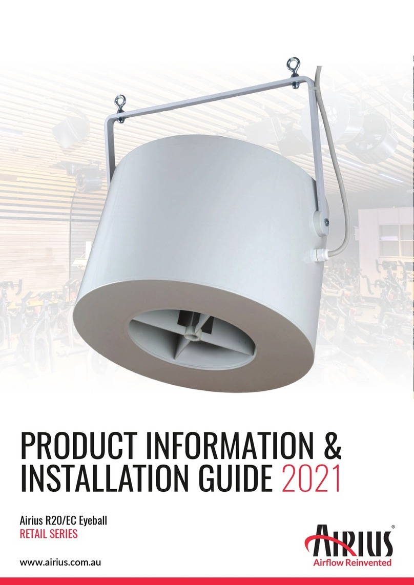
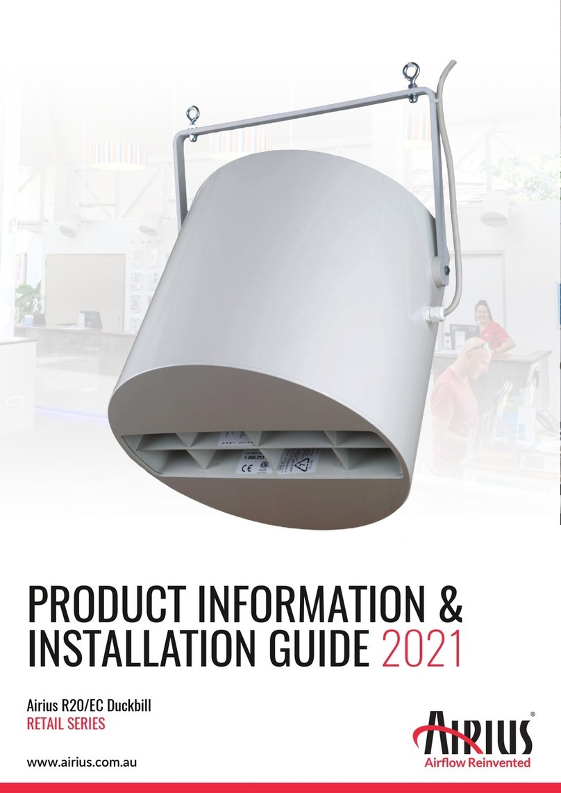
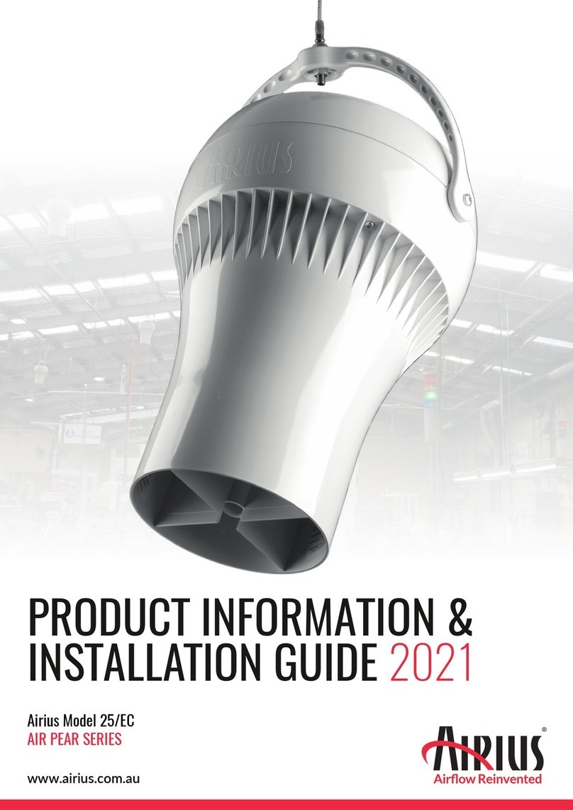
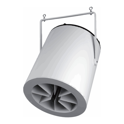
Airius SAPPHIRE Series User manual

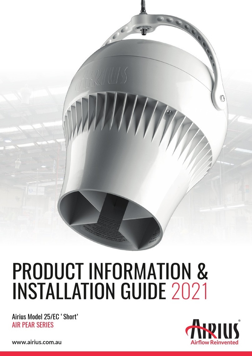
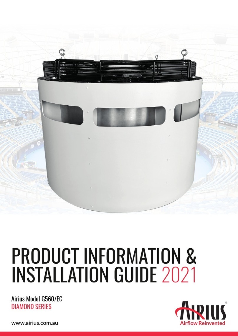
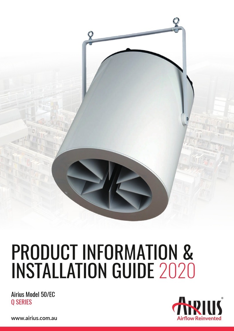
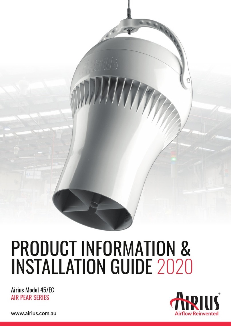
PRODUCT INFORMATION &
INSTALLATION GUIDE 2021
Airius Model G400/EC
SAPPHIRE SERIES
www.airius.com.au

+61 (2) 6608 2736 |info@airius.com.au |www.airius.com.au
SS-G400/EC-230V
2
Product Information & Installation Guide
SAPPHIRE SERIES - Model G400/EC
IP54 Rated
INGRESS PROTECTION
MOTOR
Single Phase
Electrically commutated, variable speed 92% efficient motor
German EBM Papst EC motor
230 Volt @ 50/60 Hz
OPERATING TEMPERATURES
Min start temp (approx.) = - 10° C
Min running temp = - 25° C
Shut off = 135° C
Reset = 125° C
HOUSING
PC/ABS Resin - Inc. internal fixed blade stator
5VA flame resistance rating
1.8m steel safety leash cable (fastened to housing)
NOISE LEVELS
Sound Power Level = 80 dB(A)
Sound Pressure Level @ 3 mts = 60 dB(A)
Sound Pressure Level @ 6 mts = 53 dB(A)
Sound Pressure Level @ 10 mts = 49 dB(A)
Note: A typical free field environment over a reflecting plane.
All acoustic testing conducted at 230 Volt, 50Hz and undertaken at the
EBM- Papst Acoustic Laboratories in Connecticut USA during August 2014
Please contact Airius for full Noise Testing Report
WARRANTY
5 years full manufacturers replacement from date of despatch.
Subsequent 5 year 'half new price' rebuild cover
ACCESSORIES & OPTIONS
Multiple speed control options available:
- Full 0-100% potentiometer speed control option
- Fully programmable Airius touch screen controller
- Airius PearLink WiFi Control
Fully BMS controllable
Bacnet Protocol for individual fan control
For horizontal installations Airius recommend the use of the Airius
proprietary cradle or a second cable or rod attachment to the
discharge end to provide balance
COVERAGE COOLING HEATING
Ceiling Height = 8m - 11m = 10m - 16m
Floor area = Up to 120m² = Up to 250m²
All data is indicative only and can change subject to application. For
more accurate design please contact Airius Oceania
COLOUR
Off-White, Black or Grey available
MODEL G400/EC DIMENSIONS AND PROPERTIES
Free hanging units can be angled up to 90º off vertical
Vertical attachment point provided near discharge.
495mm
340 mm
UNIT SIZE
Weight:
Total Height:
*Motor data provided by motor manufacturer and is subject to change at anytime
¹Velocity profile tested in situ
STANDARD
13.60 kgs
340 mm
Height to Rim: N/A
Diameter: 495 mm
MOTOR 230V @ 50 Hz
RPM*:
Watts*:
L/S*:
m3/hr:
Centre Line Velocity¹:
390
1660
1561
5620
2.79 m/s @ 10 m
AMPS*: 2.24
Thrust*: 14.32 Newtons

VELOCITY PROFILE
3
SS-G400/EC-230V
Product Information & Installation Guide
SAPPHIRE SERIES - Model G400/EC
PREPARATION
Install electrical circuit(s) and outlet(s) in accordance with national
and local electric codes.
Outlets should generally be mounted vertically unless a “twist/
locking” type is being used.
Wall switch may be installed in circuit to disable power and prevent
electrical hazards when servicing.
Confirm electrical continuity of Airius unit on the ground before
permanently mounting in the ceiling.
OPERATION
Designed to operate 24 hours-a-day, 7 days-a-week to maintain air
circulation/thermal equalization/humidity equalization.
Use optional speed control to fine tune RPM if needed.
MAINTENANCE
Frequency of cleaning will vary by application and environment.
You may clean the plastic housing with a damp warm cloth, using
mild household detergents.
Do not use petroleum products, thinners or solvents to clean any
part of the Airius unit.
If the Airius unit fails, contact manufacturer.
MATERIALS & PROPERTIES
Constructed from recyclable materials.
The outer shell, stator and fan blades are fire rated 5VA materials.
Power cord is a 1.8m, 3 wire, 1.02 mm diameter 300VAC rated
electrical cord - CE/EU compliance rated as HO5VV (PLUG NOT
SUPPLIED).
Electrically commutated, variable speed 92% efficient motor.
Motor is thermally protected. Shutoff is at 135°C & reset is at
125°C.
No lubrication required. Bearings are sealed.
UNIT PLACEMENT
INSTALLATION
Do not hard connect fans in excess of 10 kgs unless agreed with
Airius prior to Installation. When attaching it is preferred if some
chain or cable is used between fan and the support. However it is
not imperative.
For Cooling the Airius fan should be located to suit client’s require-
ments. Suggested locations are from just under the ceiling or closer
to the floor to ensure suitable air-cooling flow.
For Heating or Conditioned Spaces the Airius fan should be
securely installed as close as possible to the ceiling.
For combination applications fans can be installed close to ceiling
or lowered slightly. Contact Airius for design details and assistance.
The Airius unit performs best when air column from the nozzle is
unimpeded to the floor.
The Airius unit should not be mounted directly in front of heat
ducts, vents or any other high heat source.
Use professionally installed hardware, capable of supporting a
minimum of five times the weight of the fan unit.
Hardware to hang the unit includes but is not restricted to: Hooks,
chains, cables, carabiners, bridle rings, beam clamps and bolts.
Density of the placement is directly related to the effectiveness,
performance and savings.
Mount out of reach from people and animals.
Floor plans, mezzanines, office locations, machinery, people
placement, plumbing, lighting, duct work, electrical systems, natural
light/air systems, cranes, doors, windows, ventilation and fire
suppression systems are all factors in properly locating the Airius
system within the ceiling.
> 2.79 m/s > 2.00 m/s > 1.55 m/s > 1.15 m/s> 4.36 m/s
0
1.5 m
1.5 m
12 m 15 m 18 m10 m
7 m3 m

+61 (2) 6608 2736 |info@airius.com.au |www.airius.com.au
4
SS-G400/EC-230V
Product Information & Installation Guide
SAPPHIRE SERIES - Model G400/EC
Unistrut or Ceiling Beam
PLUG NOT SUPPLIED
CHAIN HUNG (STRAIGHT)
Receptacle Rated
240 VAC
240 v Plug
(single phase)
300 VAC Rated Cord
Furnished 2m
Unit Control Data Cable
To Controller OR mounted WiFi Module
Cable Tie
Cord Secured
To Control Module
Airius Air Circulation
& Destratification Fan
Intake
Exhaust
2 x 1.2 metre chains rated @ 102 Kgs each
(Supplied). Chains can be attached using
caribiners, bolts, Chemsets or Dyna Bolts.
If hung more than 1.2 metres below the
roof, Airius recommend 4 x chains attached
equally around the fan and splayed
outwards up to 20° off vertical.
Mounting Point
Mounting Point
Unistrut or Ceiling Beam
CEILING FIXED (STRAIGHT)
PLUG NOT SUPPLIED
Receptacle Rated
240 VAC
240 v Plug
(single phase)
300 VAC Rated Cord
Furnished 2m
Cable Tie
Cord Secured
To Control Module
Airius Air Circulation
& Destratification Fan
Mounting Point
Intake
Exhaust
Units can be angled
up to 90° off vercal
2 x 1.2 metre chains rated @ 102 Kgs each
(Supplied). Chains can be attached using
caribiners, bolts, Chemsets or Dyna Bolts.
If hung more than 1.2 metres below the
roof, Airius recommend 4 x chains
attached equally around the fan and
splayed outwards up to 20° off vertical.
Factory fitted eye bolt
Unit Control Data Cable
To Controller OR mounted WiFi Module
Factory fitted eye bolt

+61 (2) 6608 2736 |info@airius.com.au |www.airius.com.au
5
SS-G400/EC-230V
Product Information & Installation Guide
SAPPHIRE SERIES - Model G400/EC
PEARLINK
Reduce installation cost & control your
Airius fan system over 2.4Ghz WiFi
DISTRIBUTED COMFORT
The PearLink control system offers total fan control from a
desktop or mobile device. It integrates with existing Wi-Fi to
provide wireless connectivity for monitoring air
temperatures and stratification levels for cooling and heating
applications and to provide individual or grouped fan control.
This factory installed option will replace all control wiring and
manual wall controls. Each installation can, at a small cost,
include a floor sensor to be installed near your thermostat to
monitor room temperature and stratification levels.
WHERE WE HELP
»Reduce installation cost by eliminating control wiring
»Control fans individually or in groups over 2.4Ghz WiFi
»Provide fan control from anywhere in the world on your
portable device or laptop
FEATURES
»Interface is web-based (Chrome/Firefox), iOS, or Android
»Monitor temperature and humidity at fan and floor level
»Utilise temperature information to provide cooling air flow
»Monitor Delta-T (stratification level)
»Monitor fans via the integrated tachometer
»Alerts for run time and/or stratification
»Upgrade firmware via Over The Air (OTA) encrypted
firmware updates

+61 (2) 6608 2736 |info@airius.com.au |www.airius.com.au
6
SS-G400/EC-230V
Product Information & Installation Guide
SAPPHIRE SERIES - Model G400/EC
AIRIUS FAN SYSTEM
AIRIUS CONTROLS SERVER
PHONE OR TABLET
Housing: PC/ABS, Off white (cool gray 2c)
Mounng: Factory installed at time of ordering.
Power Consumpon
Idle: 16mA
TX/RX: 200mA
Wi-Fi Characteriscs
802.11b/g/n 2.4 GHz
TX Power 18 dBm @ 1DSSS
RX Sensitivity -96 dBm @ 1 DSSS
Range 100 meters
Sensors & Accuracy
Temperature Sensor +/- 0.5˚C
Humidity Sensor +/- 1% RH
Tachometer +/- 3%
Interface
Web-based (Chrome/Firefox), iOS, or Android (Mobile apps
available in App Store and Google Play Store)
Requirements
2.4 GHz Wi-Fi network
Phone or tablet with iOS 8 or later, or Android 4 or later required
for setup
Browser for accessing the web dashboard to control devices (PC or
MAC)
A free PearLink Account
Operang Condions
Temperature 0 to 48.8˚C
Humidity Up to 90% RH
Altitude Up to 3,300 mts
Ordering
The PearLink control is a factory installed option. Please refer to the
individual model data sheets for configuring your fan.
Warranty
1 years parts and workmanship.

7
SS-G400/EC-230V
Product Information & Installation Guide
SAPPHIRE SERIES - Model G400/EC
PEARLINK
Quick Setup Guide
ACCOUNT CREATION
Once you have purchased your Airius Wi-Fi fans, simply download the free 'Pearlink Wireless Fan Control' app from the app
store or visit https://controls.airiusfans.com/ dashboard/login and create an account using your email address to log in.
This is your command-and-control portal for the Airius fans at your facility. You can use the web based dashboard or the the
Airius PearLink mobile app, available for both iOS and Android, to operate fans to fully control the air movement in a room.
What you will need before moving on:
> Your Wi-Fi network name and associated password
> Android, iOS device, laptop or desktop computer (for provisioning)
> Height of each fan A.F.F. (above finished floor)
To begin, please download and install the Airius 'PearLink Wireless Fan Control' app, which can be found on the Google Play
or Apple Stores, or visit:
>
https://controls.airiusfans.com/dashboard/login.
email: [email protected]

+61 (2) 6608 2736 |info@airius.com.au |www.airius.com.au
8
SS-G400/EC-230V
Product Information & Installation Guide
SAPPHIRE SERIES - Model G400/EC
> >
> >
PROVISIONING DEVICES
The Airius fan system should be installed, powered and within Wi-Fi range along with the Android/iOS device used to
provision the fans. The floor sensor should be located within the same space, connected to power using the small transformer
supplied and installed 1.5-1.8 mts A.F.F. Preferably next to your existing thermostat.
Open the Airius App and enter your email address and password to log in. You are now ready toprovision your devices.
Note: the screen shots are from an Android device and might vary slightly for iOS devices.
Press the “Add new device” button: Grant Wi-Fi Permission Enter your Wi-Fi credentials
Press the “Ready” button: Choose your device. Provision all
floor sensors before any fans.
App will provision device

+61 (2) 6608 2736 |info@airius.com.au |www.airius.com.au
SS-G400/EC-230V
9
Product Information & Installation Guide
SAPPHIRE SERIES - Model G400/EC
>
>
>
>
Name the device Continue Enter the associated invoice number
Enter the ceiling height where the
fan is installed
Review the information and select
the correct fan model from the drop
down menu
Select, “Add new device and apply
most recent profile” > Follow the
same steps for each device

+61 (2) 6608 2736 |info@airius.com.au |www.airius.com.au
SS-G400/EC-230V
10
Product Information & Installation Guide
SAPPHIRE SERIES - Model G400/EC
The device screen shows your
device list. Press and hold will turn
a device on/off. Pressing once will
pull up the following screen for the
specific device.
Individual device view. You can
adjust individual fan speed, see the
air temp/humidity at the fan and
the rpm. Delta T = Fan temp - Floor
sensor temp.
The group screen shows your fan/
sensor groupings. Create a new
group by pressing on the “Create
new group” button.
Name your group and select the
devices you would like to add to this
group. You now have the ability to
control the fan speed of all devices
within that group as well as on/off.
The stats tab shows temperature
and humidity at the device over
various periods of time. You can
export this information as a csv
from this view.
>
DEVICE CONTROL
The PearLink app allows for individual and group fan control. PearLink will monitor the air temperature at the fan and at the
floor to provide a delta temperature. The humidity and air temperature will be logged and viewed within the app. This data can
be exported as a csv file.

+61 (2) 6608 2736 |info@airius.com.au |www.airius.com.au
SS-G400/EC-230V
11
Product Information & Installation Guide
SAPPHIRE SERIES - Model G400/EC
Under the individual device view,
select the “i” icon then the gear
icon in the upper right portion of
the app.
Under “Actions” select
“Reconfigure”
At this screen, you can enter the
network name and/or password
changes.
> >
NETWORK MIGRATION
If you need to change your Wi-Fi network name or password for any reason, you must follow this process. If the name or
password is changed before this step, the devices cannot be connected to. The only way to recover them is to revert back to
the old network name and password. The following process will need to be repeated for all devices.

+61 (2) 6608 2736 |info@airius.com.au |www.airius.com.au
SS-G400/EC-230V
12
Product Information & Installation Guide
SAPPHIRE SERIES - Model G400/EC
BMS CONTROL WIRING
range of
GENERAL NOTES
0-10 V signal allows infinitely variable open loop speed control
Connecting the red and yellow leads will allow EC fans to operate
at full speed
A single controller can be used to control multiple fans with the
same speed setting
The BMS generates this voltage to send to the signal (yellow)
Yellow is labelled as 0-10VDC because that is the acceptable
range of voltages that the fan will accept
Fan 1Fan 2 Fan 3
Blue (Ground)
Tachometer PWM
1 Pulse = 1 Revolution
Yellow (0-10 VDC)
Blue
Yellow
White
Blue
Yellow
White
Blue
Yellow
White
Blue (Ground)
Yellow (0-10 VDC)
Tachometer PWM
Fan
Blue
Yellow
White
White can also be used for
fault finding by verifying the
revolutions of the fan.

+61 (2) 6608 2736 |info@airius.com.au |www.airius.com.au
SS-G400/EC-230V
13
Product Information & Installation Guide
SAPPHIRE SERIES - Model G400/EC
POTENTIOMETER EC (0-10V) NON-POWERED SPEED CONTROLLER
FEATURES
WIRING
OPERATION
Input Voltage: 10VDC
Output Voltage: 0-10VDC
1) Open the front panel by using a flat head screwdriver
3) Install the front panel as shown in the following diagram
2) Wire according to the diagram on the previous page
Rotating the dial will change the output voltage from 0VDC
to 10VDC and change fan speed. The push button is used
for on/off control.
The indicator light shows the on/off power status.
CAUTION
Electrical installations should only be carried out by qualified
personnel only. Follow safety measures to avoid electric shock.
!
3164849
CONFORMS TO UL Standard 507
C
PC/ABS
POT-1
+
-

+61 (2) 6608 2736 |info@airius.com.au |www.airius.com.au
SS-G400/EC-230V
14
Product Information & Installation Guide
SAPPHIRE SERIES - Model G400/EC
TOUCH SCREEN EC FAN CONTROLLER
SPECIFICATIONS CONTROLLER DESCRIPTION
Operating voltage
Mounting
Display
Operating Temp
Storage Temp
Relative Humidity
Weight
Protection
Programming Port
Connections
24V DC ONLY (By Others)
Surface mount backbox option
3.5” Resistive touch-screen
320x240 pixel resolution
65k colours
5..50oC
-25..+75oC
%5..95 rh, non-condensing
165gr ( 225 gr with packaging )
IP30 according to EN 60529
Standard Micro USB cable
Screw terminals, max 1 mm2(26-16 AWG)
Overview
The Airius Touch Screen Controller is a programmable
room controller ideal for managing Airius EC fans.
The unit has no on-board inputs & outputs, but is
able to connect to a multitude of external IO, due
to multiple communication ports and protocols.
Integrated temperature sensor is standard.
Display / User Interface
3.5” resistive color touch-screen. 65K colors.
Powered by SEDONA Framework
The Sedona Framework™ provides a complete software platform for
developing, deploying, integrating, and managing pervasive device
applications at the lowest level.
It brings the power of programmable control and the Internet down
to extremely inexpensive devices.
The Sedona Framework distributes decision making control and
manageability to any device and brings intelligence and connectivity
to the network edge and back.
86mm
104mm
25mm

+61 (2) 6608 2736 |info@airius.com.au |www.airius.com.au
SS-G400/EC-230V
15
Product Information & Installation Guide
SAPPHIRE SERIES - Model G400/EC
INPUT OUTPUT MODULE FOR AIRIUS TOUCH SCREEN CONTROLLER
Compact Modbus RTU input/output module for the Airius room controller
Real-time clock
SPECIFICATIONS DIMENSIONS
Operating voltage
Power Consumption
Dimensions
Installation
Protection
Connections
Universal Inputs
Relay Output
Triac Outputs
Modulating Outputs
Expansion Port
Operating Temp
Storage Temp
Weight (net/gross)
230V DC +10% -5%, 50/60Hz
Max 3.5 VA (including Airius touch screen,
excluding field devices)
158 x 86 x 60 mm
Standard 35 mm rail mount
IP30 according to EN 60529
Screw terminals, max 1.5 mm² (AWG 16)
8 inputs
(see table for sensor signal compatibility)
4 Relays, 230 V DC / 5A
1 Relay, 230 V DC / 10A
2 Triacs, 0.1A@230V DC
0.5A@24V DC
4 outputs 0(2)-10 VDC, 2mA max
(2 configurable as digital in)
module (RK4)
5..50oC
-25..+75oC
400 gr / 530 gr
750 gr / 890 gr
(aux. 24V DC output versions)
Indoor Secondary
Temperature Sensor
Connection: U16
Fire Alarm Connection
(By Others): UI1

+61 (2) 6608 2736 |info@airius.com.au |www.airius.com.au
SS-G400/EC-230V
16
Product Information & Installation Guide
SAPPHIRE SERIES - Model G400/EC
CONNECTIONS
M/TIO DESCRIPTION
General
M/TIO modules provide a compact input/output solution for Modbus
RTU master controllers.
The unit has incredibly flexible input / output configuration that
allows many applications to becontrolled by a single device.
A combination with any Modbus wall unit greatly simplifies
installation on the wall-unit side, as
the IO module can be located close to the terminal unit being
controlled, with only communication wiring into the wall unit. The
mains powered versions eliminate the need for additional power
supplies or transformers further reducing cost and installation labor.
M/TIO also hosts a battery backed-up real-time-clock..
Relay Outputs
5 relay outputs are provided. Each relay can be used independently,
and a specific set of three can be configured for 3-speed fan control.
Universal Inputs
8 inputs are provided, configurable as below:
Triac Outputs
2 triac outputs are provided with flexible configuration options,
allowing control of on/off thermoelectric (PWM) or floating
actuators or relays. The triacs can be independently
configured to control different loads. However, due to internal
connections, all loads must be supplied from the same AC voltage.
Floating (three-position) configuration requires use of both
triacs.
Modulating Outputs
Four 0-10VDC analog outputs are provided for controlling
modulating valve or damper actuators. Two of these can be
configured to function as digital inputs.
Expansion Port
Up to two RK4 modules can be connected to the device with a
ribbon cable, providing a total of 8 additional relay outputs
Real Time Clock
4 time-schedules can each be independently associated with a relay
output through configuration parameters. Each schedule allows 28
sets of start/stop times per day of the week.
Pt1000 NTC0-19 VDC Voltage Free Contact
In 1
In 2
In 3
In 4
In 5
In 6
In 7
In 8

+61 (2) 6608 2736 |info@airius.com.au |www.airius.com.au
SS-G400/EC-230V
17
Product Information & Installation Guide
SAPPHIRE SERIES - Model G400/EC
WIRING DIAGRAM - 4 OR 8 FANS OR GROUPS OF
34
3637
T
FAN
12
R9
R1
56
R19R20R21
LMH
-
S
B-
A+
MU
D+
SB-
A+
D- MP
T
A+ B- S
RS485
RS485
DALI MPB
U
SRS485
24V
!
78
230VAC
910
AO3
Y
T
11 12
AO4
Y
T
AO5/DI9
Y
T
AO6/DI10
Y
T
UI4
IN
T
UI3
T
UI2
T
UI1
13 14 15 16 17 18 19 20 21 22 23 24
IN IN IN
383940
OUT 10
DO8 DO7
333435
RS485
3132
UI8
IN
T
2930
UI7
IN
T
2728
UI6
IN
T
2526
UI5
IN
T
24V DC ONLY
(By Others)
A+ B- S
34
3637
T
FAN
12
R9
R1
56
R19 R20R21
LMH
78
230VAC
910
AO3
Y
T
11 12
AO4
Y
T
AO5/DI9
Y
T
AO6/DI10
Y
T
UI4
IN
T
UI3
T
UI2
T
UI1
13 14 15 16 17 18 19 20 21 22 23 24
IN IN IN
383940
OUT 10
DO8DO7
333435
RS485
3132
UI8
IN
T
2930
UI7
IN
T
2728
UI6
IN
T
2526
UI5
IN
T
A+ B- S
N
L
-
+
-
+
-
+
-
+
M-TIO H
M-TIO H
BLUE
YELLOW
BLUE
YELLOW
BLUE
YELLOW
BLUE
YELLOW
BLUE
YELLOW
BLUE
YELLOW
BLUE
YELLOW
EC Fan EC Fan
EC Fan EC Fan
EC Fan EC Fan
EC Fan EC Fan
-
+
-
+
-
+
-
+
Please note: Up to 10 fans (subject to fan type) can be connected to one input channel.
BLUE
YELLOW
-
+
T
78
230VAC
910
AO3
Y
T
11 12
AO4
Y
AO5
13
3334
3
5
RS485
A+ B- S
T
78
230VAC
910
AO3
Y
T
11 12
AO4
Y
T
AO5/DI9
Y
T
AO6/DI10
Y
UI
13 14 15 16 17
333435
A+ B- S
RS485
31 2930
UI7
T
2728
UI6
IN
T
2526
UI5
IN
T
PA+B-S
S
RS485
PBU
-
MU 24V
!

+61 (2) 6608 2736 |info@airius.com.au |www.airius.com.au
SS-G400/EC-230V
18
Product Information & Installation Guide
SAPPHIRE SERIES - Model G400/EC
Connect to
Port 2 Only
AIRIUS TOUCH SCREEN CONTROLLER WITH FIRE ALARM INPUT (BY OTHERS)
AND EXT TEMP SENSOR - 4 FANS
R-ION
34
3637
T
FAN
12
R9
R1
56
R19 R20 R21
LM H
78
230V DC
910
AO3
Y
T
11 12
AO4
Y
T
AO5/DI9
Y
T
AO6/DI10
Y
T
UI4
IN
T
UI3
T
UI2
T
UI1
13 14 15 16 17 18 19 20 21 22 23 24
IN IN IN
383940
OUT 10
DO8 DO7
333435
RS485
3132
UI8
IN
T
2930
UI7
IN
T
2728
UI6
IN
T
2526
UI5
IN
T
A+ B- S
N
L
T
M-TIO 1
Fire Alarm
(By Others)
M-TIO H
-
+
-
+
-
+
-
+
BLUE
YELLOW
BLUE
YELLOW
BLUE
YELLOW
BLUE
YELLOW
EC Fan
EC Fan
EC Fan
EC Fan
Ceiling
temperature
sensor
24V DC ONLY
(By Others)
"Voltage-free contact"
(dry contact) signal.
Normally Open.
T
78
230VAC
910
AO3
Y
T
1112
AO4
Y
T
AO5/DI9
Y
T
AO6/DI10
Y
UI
1314151617
333435
A+ B- S
RS485
MU •24V A+ B- S MP
T
MPBUSRS485-Port2POWER
D+ D- A+ B- S A+ B-
S
RS485-Port1RS485-Port1DALI
Connection
point
S
B-
A+
RS485
Port 1
D-
D+
DALI
S
B-
A+
RS485
Port 1
S
B-
A+
24V
Power
-
MU
MPBUS
MP
RS485
Port 2

+61 (2) 6608 2736 |info@airius.com.au |www.airius.com.au
SS-G400/EC-230V
19
Product Information & Installation Guide
SAPPHIRE SERIES - Model G400/EC
AIRIUS TOUCH SCREEN CONTROLLER WITH FIRE ALARM INPUT (BY OTHERS)
AND EXT TEMP SENSOR - 8 FANS
34
3637
T
FAN
12
R9
R1
56
R19 R20 R21
LMH
78
230V DC
910
AO3
Y
T
11 12
AO4
Y
T
AO5/DI9
Y
T
AO6/DI10
Y
T
UI4
IN
T
UI3
T
UI2
T
UI1
13 14 15 16 17 18 19 20 21 22 23 24
IN IN IN
383940
OUT 10
DO8 DO7
333435
RS485
3132
UI8
IN
T
2930
UI7
IN
T
2728
UI6
IN
T
2526
UI5
IN
T
A+ B- S
34
3637
T
FAN
12
R9
R1
56
R19 R20 R21
LMH
78
230V DC
910
AO3
Y
T
11 12
AO4
Y
T
AO5/DI9
Y
T
AO6/DI10
Y
T
UI4
IN
T
UI3
T
UI2
T
UI1
13 14 15 16 17 18 19 20 21 22 23 24
IN IN IN
383940
OUT 10
DO8 DO7
333435
RS485
3132
UI8
IN
T
2930
UI7
IN
T
2728
UI6
IN
T
2526
UI5
IN
T
A+ B- S
N
L
M-TIO 1 M-TIO 2
-
+
-
+
-
+
-
+
BLUE
YELLOW
BLUE
YELLOW
BLUE
YELLOW
BLUE
YELLOW
EC Fan
EC Fan
EC Fan
EC Fan
M-TIO H M-TIO H
-
+
-
+
-
+
-
+
BLUE
YELLOW
BLUE
YELLOW
BLUE
YELLOW
BLUE
YELLOW
EC Fan
EC Fan
EC Fan
EC Fan
24V DC ONLY
(By Others)
Fire Alarm
(By Others)
"Voltage-free contact" (dry
contact) signal
Normally Open.
333435
A+ B- S
RS485
T
78
230VAC
910
AO3
Y
T
11 12
AO4
Y
T
AO5/DI9
Y
T
AO6/DI10
Y
UI
13 14 15 16 17
920 21 22 23 24
I3
T
UI2
T
UI1
IN IN
2930
UI7
T
2728
UI6
IN
T
2526
UI5
IN
T
T
Ceiling Temperature Sensor
(Supplied by Airius if required)
S
B-
A+
RS485
Port 1
D-
D+
DALI
S
B-
A+
RS485
Port 1
S
B-
A+
24V
Power
-
MU
MPBUS
MP
RS485
Port 2
R-ION

+61 (2) 6608 2736 |info@airius.com.au |www.airius.com.au
SS-G400/EC-230V
20
Product Information & Installation Guide
SAPPHIRE SERIES - Model G400/EC
1Front
Exterior
Interior
Back
STANDARD WALL BOX INSTALLATION
4
3
2
Fit base unit in flush-mounted box.
Fasten metal frame to wall box with two screws*.
Fit display unit’s bottom side on the metal frame’s hinges.
Rotate display unit up on to the base unit, making sure connection
pins are aligned.
Tighten captive top screw with small screw-driver.
When removing display part
•Make sure to untighten the top fixing screw
•Pull only from the top, with two fingers on the sides
•Do not apply excessive force
*
max 6.9 mm
max 2.6 mm
max 3.5 mm
This manual suits for next models
1
Table of contents
Other Airius Fan manuals

Airius
Airius Q Series Owner's manual

Airius
Airius 45/EC User manual

Airius
Airius 25/EC Short User manual

Airius
Airius AIR PEAR Series User manual

Airius
Airius DIAMOND Series User manual

Airius
Airius RETAIL R20/EC User manual

Airius
Airius 50/EC User manual

Airius
Airius ONYX Series User manual

Airius
Airius RETAIL R20/EC Eyeball User manual

Airius
Airius PEARL S1 Specification sheet