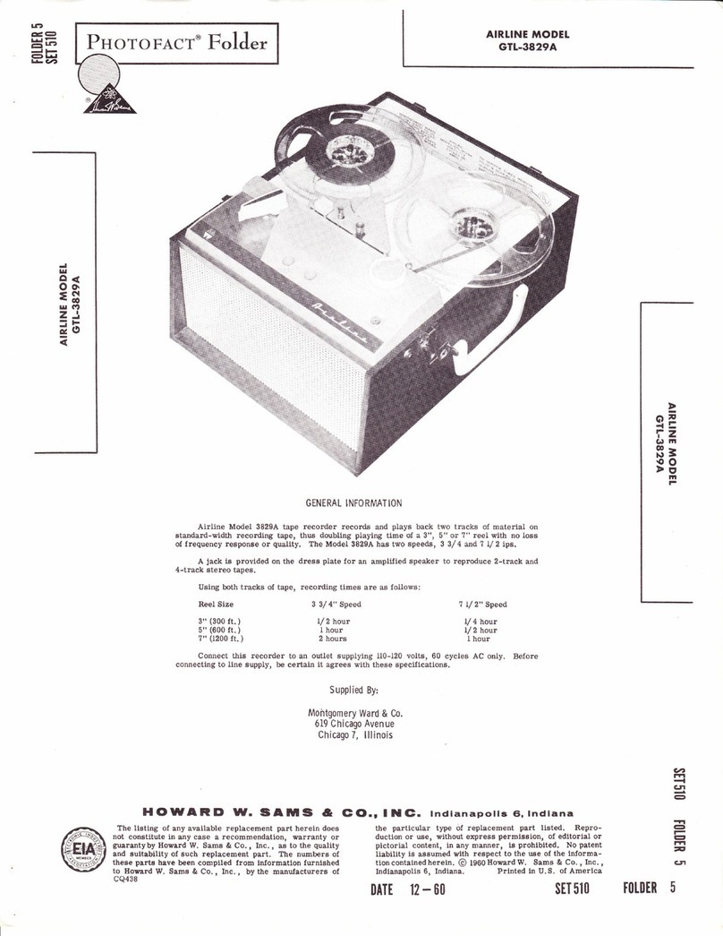
Airline GPL-3822A User manual

g:
J.
otr
r! ttt
GENERAL INFORMATION
The Model GPL-3822A will reccnd and play 4-track gtereo tapes and up to four mono-
phonic traeks on one reel of tape. It will play 2-track stereo tapes.
The Ad.A-Sound feature permits recording new parts to previously. recorded tapes.
The unit will record or play at either 3 3/4 ips or ? l,/ 2 ips.
The recorder must be operated from a 105-120 volt AC, 60 Cycle source only.
Supplied By:
Montgomery Ward & Company
6 l9 Chicago Avenue
Chicago 7, lllinois
AIRTINE
MODET GPL-3822A
(\t
6t
o
I|| clt
zj
-r
EO
?6
A
o
-3
o
I
Itt
FD
o=
!t-
TZ
G) tll
o
)9
}9
HOWARD W, SAIUS &
The listing of any available replacement part herein does not
constitute in any case a recommendation, warranty or guaranty
by Howard W. Sams & Co., Inc., as to the quality and suitability
of such replacement part. The numbers of these parts have been
compiled from information furnished to Howard W. Sams & Co.,
Inc., by the manufacturers of the particular type of replacement
cQ543
lElO., lt(E. tndianapolls €i, lndiana
part listed. Reproduction or use, without express permission, of
editorial or pictorial content, in any manner, is prohibited. No
patent liability is assumed with respect to the use of the informa-
tion contained herein. 01963 Howard W. Sams & Co., Inc.,
Indianapolis 6, Indiana. Printed in U.S. of America
(n
m
-{
o.
@
TT
o
F
t7
m
n
5
DATE 2.63 sET 618 FOLDER 4

FUNCTIONS OF CONTROLS,
Speed Control
Make sure power is on. With tape threaded,
speedcontrolswitchcanbemovedto the left for 7 Lf2"
per second or, to the right for 3 3/4" per second in
any' push-button position. Make sure the switch
"CL.ICKST' to insure proper engagement. The action
that takes place during a speed change is as follows:
Capstandrive belt (41) rides between the forked
end of speed change fork (52). When the Speed Change
button is moved to the left, the forked end of speed
change fork (52) pivots upward. This lifts capstan
drivebelt (41) high enough to be picked up by an "ear"
on motor pulley (40). The "ear", in turn, places cap-
stan drive belt (41) in the middle pulley of motor pul-
ley assembly (40), resulting in a tape speed of.7 L/2
ips. When the Speed Change button is moved to the
right, the forked end of speed change fork (52) pivots
downward. This lowers capstan drive belt (41) enough
tocontactoneof the "ears" on motor pulley (40). This
"ear", in turn, places capstan drive belt (41) in the
bottompulleyof motor pulley assembly (40), resulting
in a tape speed of 3 3/4 ips.
When the Speed Change button is moved to the
left for the 7 L/2 ips tape speed, speed change fork
(52) contacts and closes equalizer switch (56) in order
to obtain the correct equalization for the ? t/2 ips
tape speed.
Push Button
Mechanical and electrical functions relating to
the Play and Record operations are controlled by the
push buttons. In addition to starting or stopping the
tape, the PIay, Record, and Stop push buttons switch
the electrical circuits in or out when the buttons are
depressed. The mechanical functions for wind and re-
wind are controlled by the Wind and Rewind push but-
tons. The following mechanical action takes place as
each push button is depressed.
NOT E: This s equence of push-button operation orig-
inates with the Stop button depressed.
Play Button
1. Depressing the Play button releases the
Stopbutton. When the Stop button is released, tension
on brake spring (11) is relieved, allowing brake re-
lease spring (10) to puII brake rollers (3) away from
reel rests (14) and (18). Spring (94) is released aI-
lowing the actuator arm on cutoff switch (91) to rest
againsttape. If tapebreaks or spills, the actuator arm
wiIIfall into stop (Bf ) and actuate cutoff switch (91) to
stop drive mechanism.
2. Pressure roller spring (61)pullshead
mounting plate (62) forward, pressing heads against
tapeandpressure pads, also pressing pressure roller
(13?) against tape and capstan.
3. Tension applied to take-up spring (97) pivots
take-upbracket (100). Take-up bracket (100), in turn,
moves take-up clutch assembly (?0) against take-up
reel rest (18) to provide tape take-up.
PAGE 2
INDICATORS, AND SWITCHES
4. Muting switch actuator (127) is released
allowing muting switch (112) to open.
Record Button, Pause Control Lever
1. Depressing the Record button (the Pause
control lever must be held in the forward position to
allow the Record button to be depressed) releases the
Stop button. When the Stop button is released, ten-
sion on brake spring (11) is relieved, allowing brake
release spring (10) to pull brake rollers (3) away
from reel rests (14 and 18). Spring (94) is released
allowingthe actuator arm on cutoff switch (91) to rest
againsttape. If tapebreaks or spills, the actuator arm
willfall into stop (81) and actuate cutoff switch (91) to
stop drive mechanism.
2. Muting switch actuator (L27) is released
allowing muting switch (112) to open.
3. Plunger on depressed Record button moves
record switch (113) to Record position.
WI ND BUTTON
1,. Depressing the Wind button releases the
Stopbutton. When the Stop button is released, tension
on brake spring (11) is relieved, allowing brake re-
Iease spring (10) to pull brake rollers (3) away from
reel rests (14 and 18). Spring (94) is released allowing
the actuator arm on cutoff switch (91) to rest against
tape. If tape breaks, spills or ends, the actuator arm
wilifall into stop (81) and actuate cutoff switch (91) to
stop drive mechanism.
2. Plunger on depressed Wind button pivots
mutlng switch actuator (127) to switch muting switch
(112) to muting position.
3. Tension applied to fast forward spring (36)
pivots rocker arm (34). Rocker arm (34), in turn,
pivots traverse link (31) and traverse pulley (28) to-
ward take-up reel rest (18). Fast traverse beit (32),
which drives traverse pu}ley (28) from motor pulley
(40), contacts take-up reel rest (18) to wind the tape
on the take-up reel at a rapid rate.
Rewind Button
1. Depressing the Rewind button releases the
Stopbutton. When the Stop button is released, tension
on brake spring (11) is relieved, allowing brake re-
Iease spring (10) to puII brake rollers (3) away from
reelrest(14 and 1B). Spring (9a) is released allowing
the actuator arm on cutoff switch (91) to rest against
tape. If tape breaks, spills or ends, the actuator arm
willfall into stop (18) and actuate cutoff switch (91) to
stop drive mechanism.
2. Plunger on depressed Rewind button pivots
muting switch actuator (I27) to switch muting switch
(112) to muting position.
3. Tension appliedto rewind spring (35) pivots
rocker arm (34). Rocker arm (34), in turn, pivots
traverse link (31) and traverse pulley (28) toward re-
wincl reel rest (14). Fast traverse belt (32) contacts

Figure l. Top View 0f Mechanism With Top Covers Removed.
=
o
E'
F2
o4
ai-
rz
jp nt
o
l\)
)rt
rewind idler wheel (22), in turn, drives rewind reel
rest (14) to wind tape on rewind reel at a rapid rate.
CH-I and CH-z Volume Controls (Center Knobs)
The Channel 1 and Channel 2 Volume controls
(center knobs) are used to adjust recording level dur-
ing recording and the sound level during playback for
their respective channels. Turningthe controls clock-
wise increases volume level, turning counterclockwise
decreases level.
CH-1 and CH-z Tone Controls t0uter Knobs)
The Channel 1 and Channel 2 Tone controls
(outer knobs) vary the relative strength of bass and
treble frequencies during playback and monitoring for
their respective channels. The tone controls have no
effect on the signal being recorded on the tape when
recording.
Automatic I ndex Counter
Automatic index counter (??) provides a means
for locating recorded material anywhere on the tape.
Set the counter to zero at the beginning of a reel by
rotating the Reset knob. Counter bett (15), which is
connected to left-hand reei rest (14), drives the counter.
Cutoff Switch
Cutoff switch (91) is located to the left of the
head assembly. The tape falls between the tape guide
post (83) and the actuating arm of the cutoff switch (91).
Thus, when the end of a reel of tape is reached, or if
the tape should spill or break, the actuating arm of
cutoff switch (91) moves into stop (81). This action
opens cutoff switch (91) and stops the drive mechanism.
To Remove Access lnterlock Plate
f rom Bottom of Case
l. Remove six wood screws in Access Inter-
Iock.
2. Lift Access Interlock Plate away from bot-
tom of cabinet to disconnect interlock.
DI SASSENiBLY I NSTRUCTIONS
To Remove Head Cover
1. Remove six screws from bottom of case.
TI
o
F
(]
m
n
5
2.
3.
4.
Remove three screws from left side of case.
Remove three screws from right side of
Remove two screws from rear of case.
case.
PAGE 3

5. Set recorder on its side and carefullv work
mechanism out of case.
TO REMOVE HEAD COVER
Togain access to the head assembly, place both
hands on the plastic head cover. Gently push the head
cover toward the rear of the unit, at the same time,
Iifting slightly. To replace the head cover, insert the
plastic key on the cover in the cutout provided on the
top panel and turn downward until the head cover seats
into the original position.
O PERAT I NG
Tape Loading and Threading
Placeanempty reel on the right-hand reel rest,
makingsurethe three fins enter the reel slots, Piace
a full reel of standard "A" tape on the left-hand reel
rest, withtheshinysideof the tape facing the operator.
Stretch tape in line with threading slot, and lower it
into place. Attach end of tape to take-up reel and turn
the reel by hand several times until the tape has been
secured to the reel. Tape can only be loaded with the
Stop button depressed.
Tuning on the Amplif ier and Motor
Slide Power switch up to ON position to supply
powertothe amplifier and motor. Allow the amplifier
to warm up for approximately thirty seconds before
proceeding to record or playback.
Selecting Speeds
With Power switch ON and Stop button depressed
or tape running in any push button position, the Speed
Controlbutton canbe movedto the left for a tape speed
of.7 l/2 ips or to the right for 3 3/4 ips.
Caution: Neverchangespeedunlesspoweris on
andtheStop button is depressed or the tape is running
in any push button position.
To Record with Microphone
1. If making a monophonic recording, plug
microphone into Input CH-1 on left side of recorder.
Plug one microphone into Input CH-l and the other
microphone into Input CH-2 if making a stereophonic
recording.
2. Turn selector control to Record Stereo posi-
tion.
3. Slide monitor switches 1 & 2 to OFF.
4. Set tape counter to zero or make note of
counter reading.
5. Pull Pause controlforward and depress Re-
cord button.
NOTE: TheRecord button cannot be depressed
unless the Pause control is held in the forward position,
PAGE 4
To Remove Top Cover
To remove the top (front) cover, first pry the
knob off the Pause lever. Place a linger at the back
corners (at the tape guides) of the cover and press
forward toward the front. Lift the cover up and off.
To replace the top cover, reverse the procedure.
To Remove Top Plate
1. Remove six machine screws in top plate.
2. Lift top plate up and off.
I NSTRU CT I ONS
6. Adjust Volume control 1 for a monophonic
recording, AdjustVolumecontrolsl & 2 for a stereo-
phonic recording. Adjust so that the indicator Iight or
Iights just close on the loudest peaks of the sound being
recorded.
7. Release Pause control to start recording.
B. Recording will continue until Stop button is
depressed, Pause control is pulled forward, tape ends
or tape breaks.
To Record from Radio, TV, or Phonograph
Connect output of radio, TV, or phonograph
throughsuitablepatch cord or cords fitted with stand-
ardtwocircuitphone plug or plugs plugged into one or
both Inputs (CH-1 and CH-2) as required.
Proceed with recording as descr\bed in Steps 2
through 8 of "To Record with Microphone,"
To Record Four Monophonic Recordings on Tape
1. Connect source of sigaal to CH-1 input.
2. PlaceSeiectorcontrolinRecordCH-1 input.
3, Recorduntilendofreel is reached, turn full
reel over and place on left spindle.
4. Continue recording again using CH-1 input
and Channel 1 Volume control
5. When end of reel is again reached, turn lull
reel over and place on left spindle.
6. TurnSelector control to Record CH-2, con-
nectinput signal to CH-2 Input and use Channel 2 VoI-
ume control.
7. Record until end of reel is reached, turn
full reel over and place on left spindle.
L Record again using Channel 2 Volume con-
trol and CH-2 Input.
9. Use sameproceduretoplay back but instead
operate with Selector Control in Play positions.

Figure 2. Top View 0f
To Make Ad-Asound Recordings
1. Connect sound source to Input CH-1.
2. Turn Selector control to Record CH-1.
3. Turn Channei 1 monitor switch OFF.
4. Slide Adasound switch to ON.
5. Set tape counter to 0000.
6. Proceed to record. Program is recorded
on Channel 1 of tape.
7. Rewind tape to 0000"
8. Connect source of sound to be added to In-
put CH-2.
9. Turn Channei 2 monitor switch OFF and
Channel 1 Monitor switch ON.
10. Turn selector control to Record CH-2.
11. Proceed to record. Sound to be added is
recorded on Channel 2 of the tape.
12. Rewind tape to 0000,
13. To pIaV, turn selector control to trLAY,
STEREO/MONO.
L4. Depress PIay button. Adjust Tone and Voi-
ume controls for proper balance between Channel 1
and Channel 2.
Mechanism With Top Plate Removed.
To Play Stereo Recordings (4 & 2track)
1. Place reel of recorded tape on left spindle
and thread tape with take-up reel on right spindle.
2. Turn selector control to PLAY STEREO/
MONO position.
3. Set speed control to speed of recorded tape.
4. Plug in speaker units and place them about
four feet on each side of the recorder.
5. Depress Play button and adjust volume and
tone controls 1 and 2 for best balance between speak-
ers.
To Play Monophonic Tapes
1. Place reei of recorded tape on left spindle
with take-up reel on right spindle and thread tape.
2. PIug in speaker units.
3. Turn selector control to PLAYSTEREO/
MONO position.
4, Turn speed control to speed of recorded
tape.
5. Depress Play button.
6. Adjust volume and tone control 1 for de-
sired }istening level. Volume control 2 must be turned
down as low as possible.
3
o
I
Fg
or
jl-
F'
ta
6nt
o
}\t
)\,
TI
o
F
trt
m
f,
5
PAGE 5

_lt
lrll
z.l
<l
o-l
-rl
ol
e.l
FI
z.l
OI
()I
al
=l
<l
,/rl
t rrl
a.rrl
<l
CJI
Ll
=
u.ri
PAGE 6


6EU7 I2AT7 12AT7
6EU
12AU7
6AQ5
6AQ5
CHASSIS - BOTTOM VIEW (SEE PAGE I5 FOR V8 CIRCU IT COMPONTNTS)
3
o
I
F1
oI
g!-
tiz
6m
O
N'
)\'
"To Re-
Ligh fre-
ljust the
ord pole
ape. To
;s on the
rer head
ruts.
; adjust-
a signal
rter (0- 5
back the
by turn-
raximum
that the
ape. To
:re erase
, tighten
-t
o
F,
I
m
F
5
PAGE q\GE II"

ts--*
6,---o
w
ffi
H
b:---@
\ --@
rG)
€
:fr ^ :6P
,#C#ffi
d ,R.6
I
\ ---
I
8.o
iQl
i
nB ic
UtJE
d- -tu/r
tEreq\
:\ a9ii
**iln
@-Effiflflffi
EIl_HUHI[
LEgy,
A PHOTOFAS'EXPTODED'' VI€W
oHoword w. Soil. & Co.. lnc. 1963
L"
t,
325V
SOURCE
---------------r
305v
SOURCE
255V
s0uRcr
235V
SOURCE
225V
SOURCE
22sY
SOURCE
cuum tube voltmeter.
o/Mono psition.
Vluting swltches open) .
)n position.
Selector srvitch in
utton depreised
cn open) .
ttom views.
r to common ground.
for voltaqe readings.
ues makes possible a
stance readings.
tpul load connecled.
PAGE IO
FIG. 3 EXPLODED VIEW

ffil
f,F
{} B
FIGURE4 TopView 0f Mechanism With Reel Rests And Head PIate Assembly Removed"
7. When through playing side 1, tui:n fuII reel
over and place on left spindle. Thread tape and press
PIay button.
For playing four track Monophonic tapes see "To Re-
cord Four Monophonic Recordings on Tape. "
3
o
E
m,
t-D
OE
gL
1:z
L1 m
F
19
19
ADJUSTMTNTS
Take-Up Adjustment
The rpm of the take-up reel changes consider-
able as the diameter of the reel of tape increases.
Therefore, a slipping clutch is used to drive the ta-ke-
up reel at the constantly varying speeds required.
This clutch consists of take-up reel pulley (67),
which is driven at a constant speed by the take-up
bett (68). Next to pulley (6?) is fiber clutch (69). Fiber
clutch plate (69) slips on clutch felt (71), which is se-
curely cemented to take-up clutch pulley (70) and tire
(?2) drive right-hand reel rest (18) at the varying speeds
required as the tape builds up on the take-up reeI.
The take-up torque in the PIay position should
be approximately three to four ounces, measured one
inch from the center of the take-up reeI. The clutch
is adjustedby turning Nylock screw (63) until the cor-
rect pressure is obtained. If the correct pressure
cannot be obtained, disassemble the ciutch assembly
and check for a worn, dirty, or oily clutch felt (71).
If so, replace clutch felt (?1) and thoroughly clean all
associated parts.
Play-Record Head Alignment
with the tape. If not, low output, loss of high fre-
quencies, or track overlap may occur. To adjust the
play-record heads:
1. Head Height - The top of the play- record pole
piece musT-6e even rvith the top edge of the tape. To
adjust the head height, Ioosen the two hex nuts on the
side of the play-record head. After the proper head
height has been obtained, tighten the two hex nuts.
2. Azimuth Alignment - To make this adjust-
ment, obta@ent tape having a signal
of at least 5,000 cps. Connect an AC voltmeter (0-5
volt range) to the Amp. iack. While playing back the
alignment tape, pivot the play-record head by turn-
ing the three adjustment screws, until the maximum
meter reading is obtained.
Erase Head Alignment
The erase head should be adjusted so that the
pole piece is even with the top edge of the tape. To
adjust, loosenthetwohex nuts on the side of the erase
head. After the proper head height is obtained, tighten
the two hex nuts.
TI
o
F
g
m
F
5
The play-record heads must be lined up perfectly
PAGE II

To Replace The Flywheel and Capstan Assembly
1. Removethetwoscrews that mount pressure
pad bracket (8a). Remove pressure pad bracket (84).
2. Remove the screw from the left end of the
head plate assembly (62).
3. Remove "E" ring (65) from the right end of
the head place assembly (62).
4. Whileleavingsprings (60) and (6L) attached,
lift the head plate assembly (62) from the mounting
stud.
5. Remove take-up belt (68).
6. Remove capstan drive belt (41).
7. Remove "E" ring (109), thrust bearing bol-
ster (108), capstan thrust bearing (107), ball bearing
(106) "E" ring (105) and nylon washer (104) from bot-
tom of capstan shaft.
8. Lift the flywheel and capstan assembly
straight up and off the mechanism plate.
PARTS REPLACEMENT
LUBRICATION
CLEAN ING
9. To reassemble, reverse the foregoing pro-
cedure.
To Replace The Capstan Drive Belt
Capstan drive belt (41) can be removed and re-
placed without disassembling and of the drive mechan-
ism except take-up belt (68), and fast traverse belt (32).
1. Remove tale-up belt (68) from the flywheel
by lifting the belt over the top of the capstan and slip-
ping it under the head mounting bracket and guide a-
ssembly.
2. Remove fast traverse belt (32).
3. Remove capstan.drivebelt (41) from the fly-
wheel, byliftingthebeltoverthe top of the capstan and
slipping it under the head mounting bracket and guide
assembly.
Work the belt from between the forked end of
speed change fork (52) and speed change detent (42).
Liftthebelt off the motor pulley. To replace the belt,
reverse the foregoing procedure.
AII moving parts in this recorder were perma-
nently lubricated at the factory. If any parts are re-
placed, their bearing surfaces must be coated with a
lightweight grease. Do not lubricate unless any parts
are replaced.
Thebasic ruleis - do not overlubricate. Grease
must be kept off all rubber idlers and belts, the rim
of ttre flywheel, and any parts that might transfer
grease to them. If any grease falls on these parts,
wipe them with a soft cloth, and clean the belts and
idlers with alcohol. Always wipe excess lubricant
from lubricated parts.
The play-record and erase heads, capstan, and
pressure rcller (137) may accumulate tape coating
oxide, which is worn off the tape as it passes these
parts. These parts should be cleaned occasionally with
a soft cloth and alcohol.
n
L-&
\l@1
\^J
%4
fr-#t*__--@
VJ
PRESSURE ROLI,TR SPRING
TAKE-UP SPRING
PLAY
FAST FORWARD SPRI NG
PAGE 12
Figure 5. Push Button Spring Connections.

TROUBLE CHART
Sym ptom Cause Remedy
Motor and amplifier
do not operate when
switch is on.
Damaged power cord.
Def ective On - Of f
Switch
Repair or replace power cord.
Replace switch.
1.
2.
1.
2.
No sound; or sound
isluzzy, faint, ordis-
torted.
1. Over orunder record-
ed tape.
Amplifier trouble.
3. Dirty play - re-
cord head.
1. See "Operating Instructions"
Check voltages and resistances
as per schematic.
Clean head with alcohol and a
soft cloth.
2.
3.
t
Incomplete erase. 1. Dirty erase head.
Defective coil in erase
head.
Mis aligned eras e head.
1. Clean head with alcohol and a
soft cloth.
Check continuity, Replace e-
rase head, if necessary.
See "Erase Head Alignment."
2.
3.
2.
3.
Does not record. Faulty microphone or
cord.
Faulty input jack.
Faulty tube (s).
Dirty play - re-
cord head-
Op en in play-record
head.
2.
t
5.
4.
1.
2.
3.
4.
5.
1. Replace microphone or cord.
Repair or replace input jack.
Check tubes and replace defec-
tive ones,
Clean head with alcohol and
soft cloth.
Check continuity. Replace plav-
record head, if necessary.
3
o
g
E.
FD
OE
!:-
1:z
69m
o
|9
)9
Noplayback; amp -
Iifler noise onlv. Open in play-record
head.
Faulty tube Vl.
Check continuity. Replace play-
head if necessary,
Check tube V1. Replace, if ne-
cessary.
l. t.
,
2.
Poor high - fre-
quency response. Dirty play - record
heads,
Worn pressure pads.
PIay-record heads not
aligned properly.
Clean heads vrith alcohol and a
soft cloth.
Replace pressure pads.
See "Play-Record Head Align-
ment".
1.
2.
3.
l.
t
3.
No rewind. 1. Rewind spring (35) bro-
ken or disconnected.
Fasttraverse belt (32)
broken.
Replace or reconnect rewind
spring (35).
Replace fast traverse belt (32).
t.
2.
2.
No wind (fast for-
ward). 1. Fast forward spring
(36) broken or discon-
nected,
2. Fasttraverse belt (32)
broken.
1. Replace or reconnect fast for-
ward spring (36).
2. Replace fast traverse belt (32).
TI
o
I
m
F
5
PAGE 13

TROUBLE CHART Cont'd.
Symptom Cause Remedy
Brakes do not oper- 1. Brakespring (11) bro- 1, Replace or reconnect brake
ate when unit is in ken or disconnected. spring (11)'
Stop position.
Speed selector not 1. Detentspring(43) bro- 1. Repiace or reconnect detent
functioning prop- ken or disconnected. spring (43).
erly.
No tape take - up 1. Take - upspring (97) 1. Replace or reconnect take-up
when PIay button is broken or disconnect- spring (97)-
depressed. ed,
2. Take-up belt (68) bro- 2. Replace take-up belt (68).
ken,
3, Take-up clutch im- 3. See "Take-up Adjustment".
properly adjusted.
No tape drive when 1. Capstandrive belt (41) 1. Replacecapstan drive belt (41).
Pl ay button is de- broken.
press ed. 2. Pressurerollerspring 2. Replace or reconnect pressure
(61) broken or discon- roller sprinC (61).
nected.
Motor doesn't turn. 1. Capstandrive belt (41) 1. Remove top (front) cover (see
jammed on motor pul- "ToRemove Top (front) Cover"
tey ass'y. (40). Page 5) and turn exposed fly-
wheelto free capstan drive belt
(41). If drive belt (41) cannot
be freed in this manner, remove
top plate (See "To Remove ToP
Plate" Page 5) and properly re-
position drive belt (41) on motor
pulley (40).
CAUTION: Jamming ol the caPstan
drive belt (41) can only be caused
by changing speeds before turning
on the motor.
PAGE 14

V8 C I R CU IT COM PON ENTS
MECHAN ICAL PARTS LIST
=
o
I
F2
oE
al-
F7
.-
lpm
o
l\,
l)
I
2
3
4
5
6
n
I
8
I
10
11
t2
13
6t9A42
616A24
964,A388
619.462
61643169
619A28
616A24
964816 5
831A5
712A89
7 r2A9I
831A5
611-40354
824C867
854,4908
B31A?
611-40354
824C999
B 31A7
619A28
616A24
964A130r
831A5
619A28
964A41 5
619428
831A5
"8" Ring, L/4,, Dia.
Washer, Clock Steel
Roller, Brake
Washer, Bowed
Washer, Clock Steel
"E" Ring, 3/L6,, Dia.
Washer, Clock Steei
Brake Ass'y, Right & Left
Washer, Nylon
Spring, Brake Release
Spring, Brake
Washer, Nylon
Screw, #4-40 x 3/16,,
Philiips BHIIVIS
Reel Rest Ass'y, Rewind
Belt, Counter
Washer, Nylon
Screw, #4-40 x 3/16,,
Phillips BHI\{,S
Reel Rest Ass'y, Take-Up
Washer, Nylon
"E" Ring, 3/16,,Dia.
Washer, Clock Steei
* Wheel, Rewind Idler
Washer, Nylon
"8" Ring., 3/16,, Dia,
Link Ass'y, Idler
"8" Ring, 3/16" Dia.
Washer, Nylon
r4
15
16
r7
18
19
20
2T
22*
23
24
25
26
27
'n
o
F
I
m
n
5
Ref .
No. Part
No. Description
28
29
30
31
32
33
34
35
36
37
38
39
40
4t
42
43
44
45
46
47
48
49
50
51
52
53
964A850
619A28
B 31A1013
9648851
B 54A5 3
619A28
964.4912
7t2A90
712,488
619428
831A?
964A427
964A41 9
B 54A56
7tIA749
712A856
616A24
619^428
6 14-81 14
611-11254
6L6-1244
855A16
71 18855
824F21
964A418
6 1 1 -60454
Pulley Ass'y, Traverse
"E" Ring, 3rl16" Dia.
Washer, Nylon
Link Ass'y, Traverse
Belt, Fast Traverse
"E" Ring, 3/t6,,Dia.
Arm Ass'y, Rocker
Spring, Rewind
Spring, Fast Forward
"8" Ring, 3/16" Dia,
Washer, Nylon
Arm Ass'y, Drag
Pulley Ass'y, Motor
Belt, Capstan Drive
Detent, Speed Change
Spring, Detent
Washer, Clock Steel
"E" Washet, 3/16" Dia.
Nut, #8-32 x Ll/82,, Hex
Screw, #10-32 x 3/4,,,
Phiilips BHVIS
Washer, #10
Shock Mount, #2
Plate, Motor
Button, Speed Change
Fork Ass'y, Speed Change
Screw, #-32 x 1/4,,,
Phillips BHMS
Descriptiorr
- WALS CO PART NO" 14 S 3
PAGE 15

MECHANICAL PARTS LIST (CONt.d)
Ref.
No. Part
No. Descri ption
54
55
56
'b?
58
59
60
61
62
63
64
65
66
6?
68
69
?0
7t
72
73
74
?5
76
77
?8
19
80
B1
82
83
B4
85
86
8?
88
89
90
91
92
93
94
95
96
9?
9B
99
100
101
9648853
619A144
534A26
61 1-60454
616A38
831A9
1L2AB4
?1 2486
964B1433
6 1 3-605?4
831A8
619A28
I 1 1A41
954ABl 6
854454
81 1A45
964A391
871A6?
854A52
831A7
712A93
8 31A?
6 1 1 -60454
49884- 1
71 1A8B?
611-50314
61 1-60454
71 1A1483
6 1 1 -61854
?34A951
964A1 399
7644949
7r2A22
619A144
7L2AB5
964A425
964A424
523C53
6rt-20154
?1 1A1 389
1L2- A-967
964B1 5?
8 31A7
112A81
831A5
619A28
9644436
964B831
Bracket & Pin Ass'y, Speed
Change
"c" Ring, r/9" oia.
Switch, Equalizer (Includes
Screws)
Screw, #6-32 x 1/4" Phiuips
BHMS
Washer, Clock Steel
Washer, Nylon
Spring, Pressure RoIIer
ReIeas e
Spring, Pressure Roller
Head Plate Ass'y
Screw, #6-32 x 5/16", Hex
Head, Nylock
Washer, Nylon
"E" Ring, 3,/16" Dia.
Washer, Fiber
PuIIey Ass'y, Take-Up
BeIt, Take-Up
Plate, Clutch
Clutch Ass'y, Take-Up
Felt, Take-Up Clutch
Tire, Take-Up Clutch
Washer, Nylon
Spring, Take-Up Clutch
Washer, Nylon
Screw, #6-32 x 1/4" PhiUips
BHMS
Counter
Bracket, Counter
Screw, #5-40 x 3/16" RHMS
Screw, #6-32 x 1/4" Phiuips
BHMS
Stop
screw, #6-32 x L 1/8" Phillips
BHI\4S
Post, Tape Guide
Bracket Ass'y, Pressure Pad
Spacer
Spring, Idler
"c" Ring, L/B,,Dia.
Spring, Pressure Pad
Pressure Plate & Pad Ass'y
(With Shield)
Switch, Cutoff
Screw, #2-56 x ?/16" BHMS
Piate, Nut
Spring
Flywheel Capstan Ass'y
Washer, Nylon
Spring, ?ake-Up
Washer, Nylon
"E" Ring, 3/L6" Dia.
Bracket Ass'y, Take-Up
Journal Ass'y, Capstan
Ref .
No. Part
No. Descri ption
t02
103
104
105
106
107
108
109
110
111
tt2
113
114
115
116
11?
118
119
.120
t2l
t22
t23
124
r25
126
t27
128
129
130
131
132
133
134
135
136
13?
138
139
140
141
t42
61?-8114
611-80450
619A77
71 3A11
831A825
?1 1A821
619A?6
36 ?820
824A1048
964A1 287
964A1 289
60454
611
764A983
?644968
964A1 1 70
96441 169
924A929
96481005
7t4A92B
?14A584
619A144
7t2A94
71 1A751
1t2A40
?1 141364
9648841 -2
98386
?3184
?34A35
616A39
624-20604
611-20614
?1 2A98
611-41654
734A36
? 31A5 5
619- 14-B
81 1A43
964,A394
81 1A43
96481314
98384
?11A965
616A34
624- 20600
6 1 1 -40354
734A1429
Lock Washer, #8
Screw, #B-32 x 1/4" Phillips
BHI![S
Washer, Nylon
Ring, RetainirLg, 5 h6" External
eati, steet, g/16" Dia.
Bearing, Capstan Thrust
Bolster, Thrust Bearing
Ring, Retaining, 5/8" Internal
Motor
Fan
Switch & Bracket Ass'y,
Muting
Switch & Bracket Ass'y,
Recording
Screw, ffi-32x 1/4" Phillips
BHMS
Spacer
Spacer
Lever Arm & Push ButtonAss'Y
Lever Arm & Push ButtonAss'y
Buffer, Plunger
Lever Interlock Ass'y
Pin, Key-Lever Pivot
Pin, Lever Pivot
"C" Ring, 1/8" Dia.
Spring
Lever Arm
Spring, Lever Locking
Actuator, Muting Switch
Head & Bracket Ass'y, Record-
Play
Head, Record-Play
Bracket, Record- Play Head
Spacer, Head Mounting
Washer
Nut, #2-56 Hex
Screw, #2-56 x 3/8" RHN{S
Spring, Head Mounting
Screw, ]*4-40 x 1" BHMS
Washer, #4-40
Post, Tape Guide
Guide, Tape
"C" Ring, L/4" Dia.
Washer, Fiber
Roller, Pressure
Washer, Fiber
Head & Bracket Ass'y, Erase
Head, Erase
Bracket, Erase Head
Washer, Clock Spring Steel
Nut, #2-56 Hex
Screw, #4-40 x 3,/16" BHMS
Screw, #4-40 x 3,/16 " PhiUips
BH1\[,S
Guide, Tape
PAGE 16

Power Cord (Iaterlock fype) .. .,..Use BELDEN No.
Low-Loss Shielded Lead (Interconnecting) . Use BELDEN No.
Phono Pick-up Arm Cabl.e
8530 (Solid) Avallable in 12 Colors
8524 (Stranded) Avatlable in 12 Colors
Use BELDEN No. l?106 (Plastic) or 17126 (Rubber) - 6 Ft"
t?109 (Plaetic) or l?129 (Rubber) - I Ft.
8874 (Rubber) or 8895 (Plastlc)
8401 or 8421
8430 (Two Conductor-Unehielded)
8429 (Two Conductor-Shielded)
8419 (Three Conductor-shielded)
AMP PARTS IIST AND DESCRIPTION
WIRING DATA
Alternate POWER RBCTIFIERS & SIGNAL DIODES
coNTROtS
All wottoges 1/2 wlfll, or less, unless otherwise listed.
3
o
I
F>
oa
!l-
tz
q,ln
o
}9
)9
at
o
-
I
m
F
5
TU BES
Channel I AF Amp.
Channel I AF Amp. -
Cathode Follower
Channel I Otrtput
Channel 2 AF Amp.
Channel 2AFAmp.- | L1ATI
Cathode Follower I
Channel 2 Output OAQ5A (6AQ5)*
Record Level Indicator lEMMS0I
Bias Oscillator lI2AUTA
CURRS{T
RATING
( Measured )
454-2t
454-21
454-21
464-2t
ETECTROLYTIC CAPACITORS
ITEM
No.
RATING
CAP. votT. AIRIJNE
PART No AEROVOX
PART No. CORNETL.
DUBII,IER
PART No.
GENERAI.
EI.FCTRIC
PART No. MATLORY
PART No. PYRA/vtlD
PART No. SPRAGUE
PART No.
clA
B
c
c2A
B
c
c3
c4
c5
c6
c7
c8
30
30
30
30
30
30
25
25
25
25
25
25
400
400
400
400
400
400
25
25
25
26
25
25
) 285-90654
) 285-90654
273 -25694
273-25694
273-25694
273-25694
2?3 -2 56 94
2?3-25694
AFH3-39
AFH3.39
PTT82
PTT82
P1T82
PTT82
PTT82
PTT82
c0300
c0300
NLW25-25
NLW25-25
NL1V25-2s
NLWz5-25
NLW25-25
NLW25-25
xc3-40
xc3-40
MTl-11
MTI-II
MTl-II
MTl.II
MTI-u
MTI.lI
FP3?6.7
FP376. ?
TT25X25
TT25X25
TT25X25
TT25X25
TT25X25
TT25X25
MLVz5-25
MLVz5-2b
MLVz5-25
MLV25-25
MLV25-25
MLV25-25
TVL-3784. I
TVL-3784. I
TE-r20?
TE.I2O7
TE-I2O?
TE -1207
TE-I207
TE-120?
FIXED CAPACITORS
ITEM
No. RATING REMARKS
REPTACEMENT DATA
AEROVOX
PART No. CENTRALAB
PART No.
CORNELL-
DUBILIER
PART No. ELMENCO
PART No. MATLORY
PART No. SPRAGUE
PART No,
c9
cl0
crl
cL2
cl3
c14
cl5
c16
cl7
cr8
cl9
c20
c2r
c22
c23
c24
c25
c26
c27
c28
c29
c30
c3l
c32
c33
c34
c35
c36
c37
50 N?50 l0%
.02
.005 lqb
500 l0%
.01 l(%
680 r0%
.25 200V
.00r
.003 600v
50 N750 lm
.02
.005 l0%
500 l(4
.0r l(&
680 l0%
.25 200V
.001
.003 600v
250 lqo
50 N750 lq6
250 rq
50 N?50 l0%
.0033 10%
.002 tqo
.002 l0%
.02
.005
.02
.005 rffi
N?50-DI 47
BPD-02
Dr-5000
DI-500
DI-r0000
DI-680
P2 88N-2 5
BPD-OOI
P688N-003
N750-DI 4?
BPD-02
DI-5000
DI-500
DI-10000
Dr-680
P288N-25
BPD.OOI
P688N-003
Dr-250
N?50-DI 47
DI-250
N?50-DI 4?
Dr-3300
DI-2000
Dr-2000
BPD.02
BPD-OO5
BPD-02
Dr-5000
rcN-50
DD-203
)D-501
)D-681
)D-r02
x-302
rcN-50
)D-203
)D-50r
)D-68I
)D-102
x-302
)D-251
tcN-50
)D-251
rcN-50
)D-203
)D-502
)D-203
cl0Q5u
BYB6S2
PM6D5
5R5T5
PM6Sl
5R5T68
CUB2P25
BYAIODI
CUB6D3
cl0Q5u
BYB652
PM6D5
5R5T5
PM6ST
5R5T6I
CUB2P25
BYAIODI
CUB6D3
Ll0T25
cl0Q5u
Ll0T25
cl0Q5u
PM6D33
PM6D2
PM6D2
BYB6S2
BYAIODS
BYB6S2
PM6D5
ccrN-470
ccD-203
ccD-502
ccD-501
ccD-103
ccD-681
2DP-4-254
ccD-102
6DP-l-302
ccTN-470
ccD-203
ccD-502
ccD-50i
ccD-r03
ccD-68r
2DP-4-254
ccD-102
6DP-r-302
ccD-251
ccTN-470
ccD-251
ccTN-470
ccD-332
ccD-202
ccD-202
ccD-203
ccD-502
ccD-203
ccD-502
cN7-447
B-120
JL-250
GP35O
GEM-16II
GP368
GEM-2025
B-210
GEM-623
cN?-44?
B-120
JL-2 50
GP35O
GEM-16II
GP368
GEM-2025
B- 2IO
GEM-623
GP325
cN?-44?
GP325
cN7-44?
JL-233
Gp220
GP22O
B-120
B-250
B-120
JL-250
l0Tcu-Q4?
5HK-520
roTs-D50
l0TS-T50
r0rs-sl0
IOTs-T68
2TM-P25
SHK.DIO
6TM-D3O
r0Tcu-Q4?
5HK-S2O
l0Ts-D50
I0Ts-T50
l0Ts-si0
r0Ts-T68
2TM-p25
5HK-DIO
6TM-D3O
l0TS-T25
loTcu-Q4?
i0Ts-T25
r0Tcu-Q4?
l0rs-D33
l0TS-D20
loTs-D20
5HK-S20
5HK-DsO
5HK-S20
r0Ts-D50
ITEM
No. USE RESIST.
ANCE
REPLACEMENT DATA
AIRLINE
PART No. CENTRALAB
PART No. CTAROSTAT
PART No. cTs-lRc
PART No. MA!.LORY
PART No.
RIA
B
R2A
B
Tone, I
Volume, I
Tone, 2
Volume, 2
500K
500K
500K
500K
24A50413-18
24A504r3-r8
FI-41, R2-41
Fl-41, R2-41
P-500K-2, CF0l:
t-500K-z,FR-l0i
P-500K-Z,CP-0li
t-500K-z,FR-10,
PAGE 17

AMP PARTS LIST AND DESCR|PT|ON (CONTTNUED)
RESISTORS
All wottoges 1/2 watl, or less, unless otherwise li$ed.
(POW
MISCELLANEOUS
CABINETS & CABINET PARTS
(When Ordering Cobinets & Cobinet Ports, Specify Model, Chossis & Color)
R3
R4
R5
R6
R7
R8
R9
Rl0
Rll
Rl2
Rl3
RI4
Rl5
Rl6
RI?
Rr8
Rl9
R20
R2l
P'22
R23
P"24
R25
R26
R27
R28
R29
R30
R3l
R32
R33
22000
220K
lmeg
220K
2?000
ISOK
33000
lmeg
l00K
2?000
lmeg
{70f,
39K
r50K
82K
330K
270K
220K
lmeg
390Q lw
2200rl
8Q 5W
2200f}
220K
lmeg
220K
270osr
l50K
3300r}
lmeg
l00K
2?000
lmeg
4?0r)
39K
l50K
82K
330K
270K
220K
lmeg
390f, lw
2200c,
8f, 5W
47I(
4700
47K
4?00
r0K
2.Zmeg
390K
270o.
l0K
2.2meg
390K
t5r, lw
15f, Iw
1000f, lw
3900f, Iw
5600f,
r5K
r5K
PW5-8 I rw-SQ-A
R34
R35
R36
R3?
R38
R39
R40
R4t
R42
R43
R44
R45
R46
R4?
R48
R49
R50
R5l
R52
R53
R54
R55
R56
R57
R58
ITE'VI
No. USE
RTPTACbMTNT DATA
NOTESAIRLINE
PART No- Merit
PART No. Miller
PART No. Stoncor
PART No. Workmon
PART No.
LI
L2 Blas Osc.
RF Choke (38MH) 3llA20
312A50 TRANSFORMER E
ITEM
No. RATING REPTACEMENT DATA
NOTES
AIRLINE
PART No. MERIT
PART No. STANCOR
PART No. THORDARSON
PART No. TRIAD
PART No
PRI. sEc. IsEc. 2
TI ll?vAc
o.55A
* d)
480vCT
D.08eA 6.3VAC
D 2.6A 352R{9 O l.2A with Motor
TRANSFORMER (AUDtO OUTPUT)
TEM
No. IMPEDANCE REPLACEMENT DATA
NO]ES
AIRLINE
PART No. Merit
PART No. Sloncor
PART No. Thordorson
PART No. Triod
PART No.
PRI. SEC.
T2
T3 3700s}
3700f, 6-8fl
6-8f, 342.A30
342A30 A-2900
A-2900 A-3 850
A-3 850 24S05
24S05 s-63X
s-63X
SPEAKER
ITEM
No. IYPE REPTACEMENT DATA
NOTES
AIRLINE
PART No. QUAM
PART No.
srzE FIETD v. c. tMP.
3Pl
sP2 rtt( l0rt
'k l0n PM
PM 6-8fl
6-8r, 345840
345Rl0 4rOA2Z8
4L0A2Z8
IIEM
No, PART NAME AIRIJNE
PART No. NOIES
lfl
M2
M3
M4
M5
M6
M?
M8
M9
Ml0
Mll
rA2
Ml3
Head
Head
Head
Motor
Switch
Swltch
tutch
Switch
Suitch
Srfich
Swttch
Switch
Switch
Mlcrophone
98386
9838t
98386
367820
539816
532A40-1
532A40-l
532A40-l
532A40-1
534A26 .
964A1289
964A128?
523C53
445827-2
Play-Record
Erase
Ad-Asound
Selector (Rotary Wafer TYPe)
Ad-Asound (DPST srtde Type)
Power On-Off (DPST S1ide TYPe)
Monitor, Ch. I (DPST Slide TYPe)
Monitor. Ch. 2 (DPST Slide TYPe)
Equalizition (Spring Leaf TYPe)
Record (Spring Leaf TyPe)
Muting (Spring Leaf TYPe)
Motor (Micro TyPe)
NAME PART NO. DESCRIPTION
Knob
Knob
Knob
Cover
Case
Case
814A1420
8r4A14r9
8r4Al4l8-r
964A1496-2
88?DI388
964-r49?
Volume
Tone
Selector
Ilead
Speaker Wlng
Recorder
PAGE I8
Table of contents
Other Airline Voice Recorder manuals