Airrex HSC-2500 User manual

A
AI
IR
RR
RE
EX
X A
AI
IR
R C
CO
ON
ND
DI
IT
TI
IO
ON
NE
ER
R
HSC-2500 / HSC-3500
▶Thank you for purchasing an AIRREX AIR CONDITIONER.
BEFORE operation please read this user’s manual carefully.
▶ Keep this manual readily available.
▶ It is ESSENTIAL that you read the ‘NOTES ON SAFETY’carefully
before use and follow them at all times.
▶ This Air Conditioner is specified for use on a 220~240Va.c. 60Hz.
single phase power supply. You must check that the local
electricity supply is the same and have the appropriate plug fitted
by a qualified electrician.
▶ The Warranty form is on Page 15. Please complete it now and keep
in a safe place.
▶ We have a policy of continual improving to our products.
The contents (features and specifications) in this manual are
therefore subject to change without notice.
USER’S MANUAL

2
TABLE OF CONTENTS
3
5
5
5
6
7
7
8
9
10
11
12
13
14
15
■ SAFETY INSTRUCTIONS
■ DESCRIPTION
·Front View
·Back View
·Control Panel
■ OPERATING INSTRUCTIONS
·On/Off Operation
·Selection of Area/Room or Spot Cooling
·Temperature Control
·Off Timer
·Error and Warning Indicators
■ CLEANING AND MAINTENANCE
■ TROUBLE SHOOTING / ACCESSORIES
■ SPECIFICATIONS
■WARRANTY

3
SAFETY INSTRUCTIONS
The following instructions are for ensuring the user’s safety and to prevent any physical
injury or material damage. Please read carefully and follow all instructions.
There are two sections to these instructions: WARNING and CAUTION.
The following symbols are for your guidance:
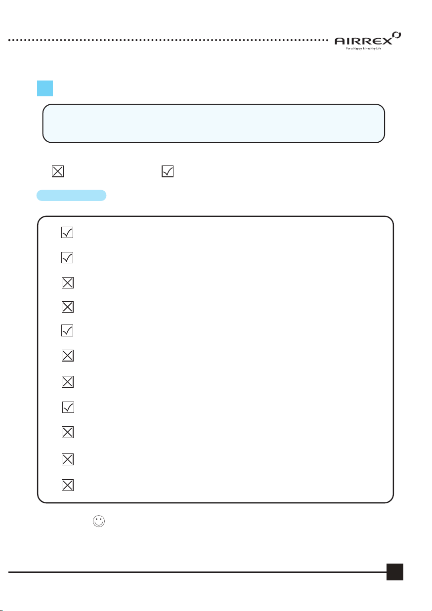
= You must NOT. = You MUST.
Keep this manual in a visible location near the cooler
for easy reference.
Use a 220~240Va.c. 60Hz. 1 Phase power supply only.
(Wrong supply may cause a fire and / or shock hazard)
Securely plug into an earthed supply.
(Unless earthed, may cause electric shock)
Do not use a damaged power cable, plug or socket.
(Short, fire or shock hazard)
Do not remove plug by pulling cable or with wet hands.
(Risk of fire and electric shock)
Before cleaning, remove plug from socket.
(Otherwise risk of electric shock)
Do not place anything on top of the machine.
(This could cause electric shock, malfunction or injury)
Do not use an extension lead unless of the approved type.
(Risk of fire and / or electric shock)
Ensure mains plug is clean and securely plugged in.
(Otherwise it may short causing smoke and fire)
Do not ‘kink’or sharply bend the power cable nor put any weight on it.
(The insulation may be damaged causing fire and/ or electric shock)
Do not turn off by removing power plug. Always turn off at control panel first.
(Risk of electric shock and / or malfunction)
Do not use this cooler on unstable or inclined surfaces. Always use on solid
flat floor. (Risk of falling causing injury, fire or malfunction)
WARNING

4
SAFETY NOTICE
GENERAL ADVICE BEFORE USE
·Ensure the safety of the location in which cooler is to be used.
·Ensure the floor or ground is smooth and sound.
·Ensure you allow at least 50cm air space all around the cooler.
·When in position LOCK the casters to prevent rolling.
·Never use the cooler at more than 2。incline
FOR MAXIMUM EFFICIENCY
·In airtight areas use vertical exhaust into ceiling.
·If possible locate exhaust outlet through a window or door to outside.
·Exhaust ducting should be no longer than 2m for maximum efficiency.
·Ensure correct electricity supply.
·The proper electricity is 220~240Va.c. / 50Hz. It will be applied and adjusted
as per customer's request.
You must supply power as per it's requirement only once it is adjusted.
CAUTION
Do not place cooler on uneven, unstable or inclined surface.
(This could cause malfunction)
When storing the cooler, ensure that it is kept in a dry, cool place.
(To prevent corrosion and malfunction)
If not being used for some time or if lightening is present, always unplug
from power. (To prevent risk of electric shock, short circuit or fire)
Do not spray water on to the cooler nor use solvents such as benzene, thinner or
alcohol for cleaning.
(There is a risk of electric shock and / or short circuit)
If the power cable is damaged this must be replaced by a fully qualified
electrician. (To avoid danger of electric shock, short circuit or fire)

5
EXTERIOR DESCRIPTION
FRONT VIEW
BACK VIEW
FLEXIBLE DUCT OUTLET (COLD AIR)
HANDLE
DIGITAL CONTROLLER
CASTERS (FRONT LOCKABLE)
ELECTRIC PANEL
(ACCESS BY AUTHORISED SERVICE
PERSONNEL ONLY)
POWER PLUG
CONDENSER OUTLET (HOT AIR)
EVAPORATOR FILTER
AMBIENT AIR INTAKE.
CONDENSER FILTER
WATER LEVEL INDICATOR
TO CHECK WATER LEVEL OF THE
CONDENSATE TANK.
CONDENSED WATER TANK
TO COLLECT WATER GENERATED
DURING COOLING.

6
EXTERIOR DESCRIPTION
① Power : Use to power On / Off.
② : Raises or lowers temperature and sleep (off) time.
③ Cool : Use to select cooling mode.
④ Low Mode : Controls fan low speed.
⑤ High Mode : Controls fan high speed.
⑥ Off Timer : To set the length of time, once turned on, that you wish the
cooler to run for. You can set 0~24 hours. Time intervals are
30mins. up to 10 hours and then 1 hour between 10 and 24 hours.
⑦ Remote : From the long distance, you can control the machine by wired remote control.
⑧Room : If the LED is On, the displayed temperature is for Room temp. If the LED
is Off, the displayed temperature is for spot temp.
⑨Comp. : When the compressor is operating, the LED is On.
⑩ Error : Error signal ( E1 : High Pressure, E2 : Low Pressure, E3 : Sensor, AF: Eva Freezing)
⑪Water Full: Red light indicates ‘Tank Full’. The compressor will shut off
automatically. Empty tank and replace in position to resume operation.
⑫ Align Drain Tank : The red light indicates the water tank is not in the correct position.
⑬ Display : Display Room/Spot temperature, and the setting temp and sleep time in case of
setting them. When the user set the sleep timer, ‘hr’will be turned on.
(Display of 'LO' : under the 0℃, Display of 'HI' : over the 50℃)
⑤
①
②
③④
⑦
⑧
⑩
⑪
⑫
⑬
⑨
⑥

7
OPERATION
RUNNING & STOP
1. START BY PRESSING THE ‘POWER’BUTTON.
·Cooler will start up automatically.
·To STOP the unit, press the ‘POWER’button once again.
2.To change fan speed, press the ‘Low’button.
3.If you wish to operate on fan only, press the ‘COOL’button. To resume cooling,
press the ‘COOL’button again.
(Note : There is a 3 minute delay when switching functions to protect
the compressor)

8
SELECTION of AREA/ROOM or SPOT COOLING
To reduce the temperature of the entire room select 'Area/Room'.
For ‘targeted’cooling of machinery, servers, or people etc. select ‘Spot Cooling’.
1. IF YOU WANT TO DISPLAY ROOM
TEMPERATURE, PUSH COOL AND BUTTON
SIMULTANEOUSLY FOR THREE SECONDS.
2. IF YOU WANT TO CHANGE TEMPERATURE UNIT
PUSH AND BUTTON
SIMULTANEOUSLY FOR THREE SECONDS.

9
TEMPERATURE CONTROL OPERATION
1. When power is ON, the setting temperature
is displayed. Default of setting temperature
is 5℃.
2. When you push either or button, the
setting temperature is changed.
3. The display showing the set temperature will
blink 3 times.
4. Limits of Room/Spot and Setting temperatures.
Room/Spot Temp. Setting range
0℃ - 50℃ 1℃ - 30℃
Cooling operates when
Room/Spot temperature is
more than
set
temperature.
Cooling stops when
Room/Spot temperature is
less than
set
temperature.

10
HOW TO SET THE ‘OFF’TIMER.
This function enables you to set the length of time you want the cooler to operate.
You can set the time period from 30min. to 24 hours in 30min. and 1 hour increments.
OFF TIMER LAMP IS ON
AFTER 1hr
1.When cooler is operating, press the ‘Off Timer’
button and set the length of time you want by
pressing ▲ or ▼.
Each time you press the button you will increase the
‘time to off’period by 30mins. up to 10 hours, and
1 hour thereafter up to 24 hours.
The display will show .5 for 30min and 1 for an hour.
e.g. One and a half hours will show 1.5.
2.When you have finished setting the time period, the
‘Off Timer’lamp will be on which indicates
the cooler is in sleep (Off Timer) mode.
3.If you press the ‘Off Timer’button during its
operation, the remaining time will be shown.
4.To CANCEL timing, press ‘Off Timer’button for ONE
second. It will then switch the timer off automatically.

11
'ERROR' and WARNING INDICATORS
The machine’s safety devices will automatically signal any problems via the display window
on the control panel. The information below shows how to read these signals.
1. WATER FULL- Display shows “FU”
When the water container is full, “FU”is displayed
and the LED “Water Full”light will be on.
2. ALIGN WATER TANK
If the water tank is not positioned correctly, the LED
“Align Drain Tank”light will be on.
3. HIGH PRESSURE
‘E1’is displayed and the ‘Error’LED will be on
when the pressure of the compressor is too high and
the high pressure switch is open.
4. LOW PRESSURE
‘E2’is displayed and the ‘Error’LED will be on
when the pressure of the compressor is too low and
the low pressure switch is open.
5. SENSOR PROBLEM
If the thermistor is short circuited or cut, ‘E3’is
displayed and the ‘Error’LED will be on.
6. ANTI FREEZING
When the temperature of the evaporator is below
-2℃, ‘AF’is displayed and the ‘Error’LED will be
on.

12
CLEANING AND MAINTENANCE
CLEANING THE AIR FILTERS
1. To remove filters, slide up a little ① and pull
towards you ②.
2. Clean the filters with water or compressed air.
3. Clean evaporator and condenser units with a
vacuum cleaner or compressed air.
MAINTENANCE
1. After cleaning, completely dry the inside of the
unit by operating on ‘Fan Mode’only for
3 to 4 hours.
2. Turn “OFF”at control panel, remove plug from
socket. Coil and store cable neatly.
3. Keep machine suitably covered to prevent
damage by damp, humidity and dust.

13
TROBULE SHOOTING
ACCESSORIES
NOT
WORKING
POOR
COOLING
TROUBLE CHECK REMEDY
●
Power plug correctly connected
● Connect plug correctly
● POWER button “OFF” ● Press POWER button to “ON”
● Blown fuse in electric panel ● Replace fuse
● Fuse (supply) blown ● Exchange fuse in board
● Breaker on switch board ● Check load capacity and reset
tripped
● Ambient temp. too high ● Use only below 45℃
(over 45℃) (HSC-3500 : 40℃) (HSC-3500 : 40℃)
● Filter blocked with dust ● Clean Filter
● Dust in heat exchanger ● Clean heat exchanger
● Obstacle against inlet side ● Remove and allow 50cm.clearance
●Ambient temp. too high ●Use only below 45℃
(over 45℃) (HSC-3500 : 40℃) (HSC-3500 : 40℃)
MODEL
ITEM
COLD
AIR
OUTLET
HOT
AIR
EXHAUST
DUCT OPTION
OPTION
Diam.
125mm
DRAWING
HSC-2500/HSC-3500
DUCT COVER
(FINISHING COLLAR)
DAMPER BASE
(FLOW CONTROL FLAP)
ALUMINIUM FILTER
CASSETTE
ALUMINIUM FILTER
CASSETTE
REDUCER REDUCES EXH.
DUCT FROM
43cm to 30cm
0.5m
3m

14
SPECIFICATIONS
Power Cable
Max. Duct Length
(Either hot or cold, not
both together in use)
Fuse in power box
in Machine body
▶
High Pressure Switch
▶
Low Pressure Switch
▶
3 min. delay timer.
▶
Fan motor protection
▶
Thermostat and relief valve for compressor
▶
Tank position indicator.
▶
Auto ‘Full Tank’shut off.
BTU/h
kW
21,000
(6.15)
25,000
(7.33)
Model H
HS
SC
C-
-2
25
50
00
0 H
HS
SC
C-
-3
35
50
00
0
Cooling Capacity
Power Supply
220~240Va.c. 50Hz. 1Ph.
Dimensions
mm. 490 X 600 X 1,303
Weight
Kg 86 90
Evaporator Air Flow ft3/m (m3/m)
459 (11-13) 565 (14-16)
Noise Level (at 1m.) Db/a
68 69
Power Consumption
kW. 2.41 2.6
Current Consumption Amp.
11 13
Refrigerant(R-407C)
grm 890 1,200
Air Filter Aluminium Mesh Cartridge
Safety Devices
DEVICE Plug
Length 3 meters
Operating Range
22℃ to 45℃ (HSC-3500 : 22℃ to 40℃)
High Pressure
kgf/cm2
26
Low Pressure
kgf/cm2
5
Cold Duct(m)
912
Hot Duct(m)
Optional
250 Va.c. 5amp.

15
PRODUCT
SERIAL NO:
DESCRIPTION AIRREX AIR CONDITIONER
MODEL HSC-2500 / HSC-3500
DATE OF PURCHASE
WARRANTY
AIRREX AIR CONDITIONERS give more reliable performance, comfort and durability
the more they are used. They are built under a strict quality assurance regime
which includes inspection both during and after production and exhaustive
reliability testing.
In the unlikely event you have any problems, please contact your dealer or
distributor. If the problem is as a result of a production fault or failure, repairs will
be undertaken free of charge during the period of warranty subject to the
following warranty conditions:
1. The warranty period is 12 months from the date of first purchase.
2. If the problem has been caused by customer error or misuse, abuse or
damage, then all repairs will be charged for.
3. This warranty applies to your country.
4. Proof and date of purchase must be supplied.
5. Please complete the details below and keep this warranty in a safe place.
6. All transport charges back to the dealer are at the customers cost. Keep all
original packaging to facilitate return. Return to customer will be at dealers cost
(if genuine warranty claim).
Name of Company
Telephone No.
DISTRIBUTOR
Name :
Address :
Telephone :
CUSTOMER
DETAILS
(Applicable to first retail purchaser only)
Warranty Period
( ) Months

● Designs and specifications of products are subject to change without prior notice for the improvement of products.
This manual suits for next models
1
Table of contents
Other Airrex Air Conditioner manuals
Popular Air Conditioner manuals by other brands

Friedrich
Friedrich WallMaster WS10 Installation and operation manual

Honeywell
Honeywell CL30XC owner's manual

AHRI
AHRI SUPERIOR Series Installation, operation & service manual

PR KLIMA
PR KLIMA GPC10AL operating instructions

Samsung
Samsung AQV12NSA Service manual

Toshiba
Toshiba RAS-M10SMUV-E installation manual

ARDES
ARDES AR5R003 Instructions for use

Carrier
Carrier RAV180 installation instructions

nedis
nedis ACMB1WT9 quick start guide

CLIMAVENETA
CLIMAVENETA i-ACCURATE i-AX Installation manual - user and maintenance

Bard
Bard THE WALL-MOUNT WA3S3-A installation instructions

Arctic King
Arctic King wwk05cr61n Energy guide