Airrex HSC-18PLUS Service manual

rev0
Operating Instruction &
Parts Manual
Model : HSC-18PLUS/24PLUS
▶Thank you for purchasing an AIRREX AIR CONDITIONER. BEFORE operation please read this
user's manual carefully.
▶Keep this manual readily available.
▶It is ESSENTIAL that you read it carefully before use, and follow it at all times.
▶The Air Conditioners are specified for use on a 115V~ 60Hz 1ph for models HSC-18PLUS, and
220V~ 60Hz 1ph for model HSC-24PLUS single phase power supply. You must check that the local electricity
supply is the same and have the appropriate plug fitted by a qualified electrici an.
▶Please complete the warranty form now and keep in a safe place.
▶We have a policy of continual improving to our products. The contents (features and specifications) in this
manual are therefore subject to change without notice.
Please read and save these instructions. Read carefully before attempting to assemble, install, operate or maintain the product described.
Protect yourself and others by observing all safety information. Failure to comply with instructions could result in personal injury and/or
property damage! Retain instructions for future reference.
AIRREX AIR CONDITIONER
Description
Airrex air conditioners operate in air temperatures from 72℉to 113℉. These air conditioners utilize eco-friendly
R-410A refrigerant. Airrex air conditioners air conditioners may require a fresh air supply for proper operation.
Includes removable, washable air filters for easy maintenance. Thermostatically protected compressor includes
high and low pressure warnings. Moves easily on (4) swivel casters (2 locking).
Air conditioners feature (2) 5" diameter front cold air discharges and a HSC-18PLUS(12") / HSC-24PLUS(12")
diameter top warm air discharge. ETL listed. Optional condensate pump that plugs directly into the portable
air conditioner.
Unpacking
After unpacking the unit, carefully inspect the unit for any damage that may have occurred during transit,
such as any loose, missing, or damaged parts. If damaged, immediately file a claim with the carrier.
NOZZLE TYPE LOUVER TYPE

rev0
Operating Instruction & Parts Manual
Cooling Capacity
Power Supply 115V~ 60Hz 1Ph 220V~ 60Hz 1Ph
19.3 X 24 X 48 19.3 X 24 X 48
Weight lb 165 171
Power Consumption
kW 1.85 2.86
Current Consumption
Amp. 16 13
Air Flow Evaporator CFM 423 459
Air Flow Condenser CFM 720 780
Nema Plug 5-20 6-20
Refrigerant(R-410A) lb 1.65 2.1
Air Filter Aluminium Mesh Cartridge
DEVICE Plug
Length 9.8 ft.
Operating Range 72℉DB 60% RH ~ 113℉DB 40%
High Pressure
psi (kgf/cm
2
)
441 (31)
Low Pressure
psi (kgf/cm
2
)
185 (13)
Cold Duct 30 ft. (Nozzle Type Only)
Hot Duct 40 ft.
250V~, 10A 250V~, 5A
SPECIFICATIONS
Power Cable
Safety Devices
Max. Duct Length
Fuse in power box
in Machine body
▶High Pressure Switch ▶Fan motor protection
▶Low Pressure Switch ▶Tank position indicator.
▶Auto ‘Full Tank’shut off. ▶3 min. delay timer.
▶Thermostat and relief valve for compressor
BTU/h
kW
Dimensions
(WxDxH)
16,800
(4.92)
23,500
(6.89)
HSC-18PLUS HSC-24PLUS

rev0
Operating Instruction & Parts Manual
WIRING DIAGRAM
Operating Instruction & Parts Manual
HSC-18PLUS
HSC-24PLUS

rev0
Operating Instruction & Parts Manual
The following instructions are for ensuring the user's safety and to prevent any physical injury or material
damage. Please read carefully and follow all instructions. There are two sections to these instructions:
WARNING and CAUTION.
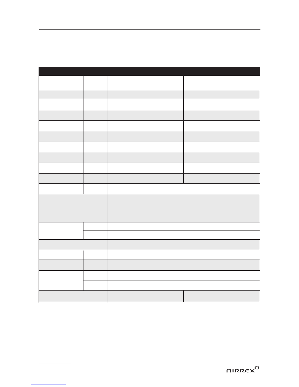
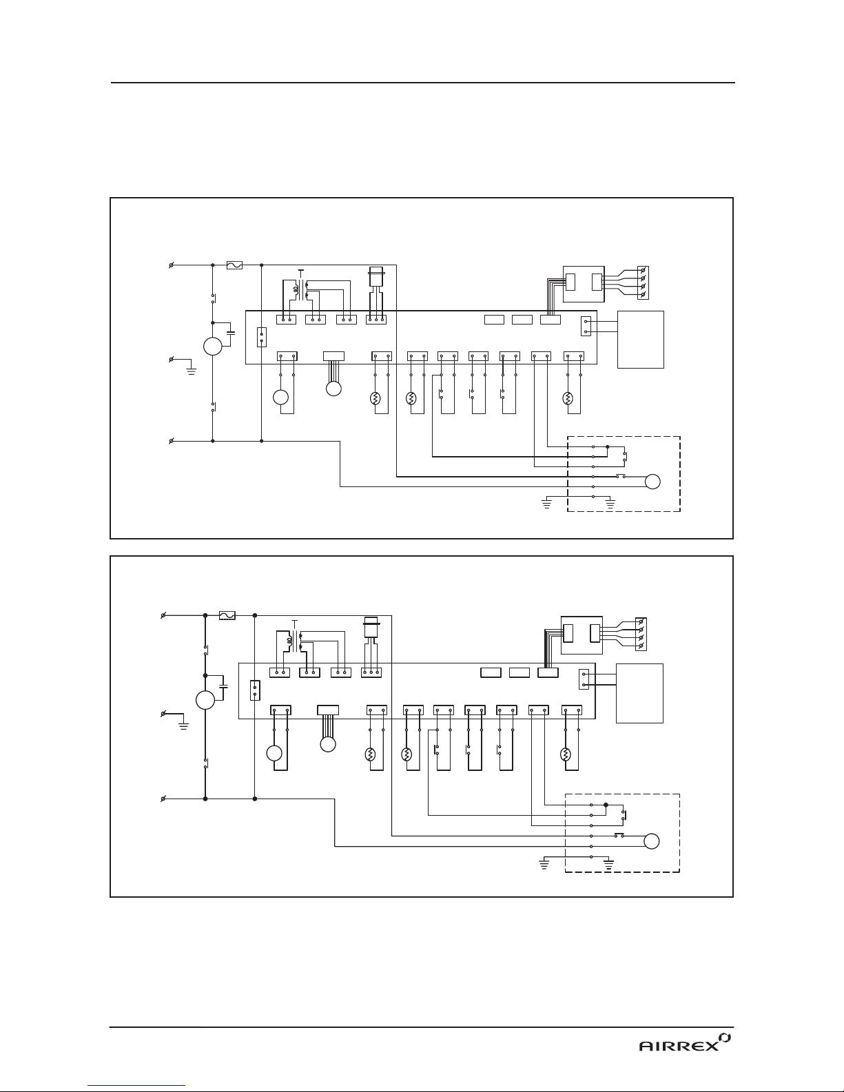
* Use a 115V~ 60Hz (HSC-18PLUS), 220V~ 60Hz (HSC-24PLUS) 1 Phase power supply only.
(Wrong supply may cause a fire and / or shock hazard)
* Ensure the safety of the location in which cooler is to be used. * Ensure the floor or ground is smooth and sound.
* Ensure you allow at least 20inch air space all around the cooler. * When in position LOCK the casters to prevent rolling.
* Never use the cooler at more than 2。incline.
FOR MAXIMUM EFFICIENCY DUCT INSTALLATION
*In airtight areas use vertical exhaust into ceiling. * The duct should be established before using.
* If possible locate exhaust outlet through a window (Standard Duct Size : 1ft, 5" dia.)
or door to outside.
* Ensure correct electricity supply.
GENERAL SAFETY INFORMATION
Operating Instruction & Parts Manual
* Securely plug into a grounded outlet. (Unless earthed, may cause electric shock)
* Do not use a damaged power cable, plug or socket. (Short, fire or shock hazard)
* Do not remove plug by pulling cable or with wet hands. (Risk of fire and electric shock)
* Before cleaning, remove plug from socket. (Otherwise risk of electric shock)
* Do not place anything on top of the machine.
(This could cause electric shock, malfunction or injury)
* Do not use an extension cord. (Risk of fire and / or electric shock)
* Do not ‘kink’ or sharply bend the power cable nor put any weight on it.
(The insulation may be damaged causing fire and/ or electric shock)
* Do not turn off by removing power plug. Always turn off at control panel first.
(Risk of electric shock and / or malfunction)
* Do not use this cooler on unstable or inclined surfaces. Always use on solid
flat floor. (Risk of falling causing injury, fire or malfunction)
* A damaged power supply cable must be replaced with a new power supply
cord obtained from the product manufacturer and not repaired.
* Do not place cooler on uneven, unstable or inclined surface.
(This could cause malfunction)
* When storing the cooler, ensure that it is kept in a dry, cool place.
(To prevent corrosion and malfunction)
* If not being used for some time or if lightening is present, always unplug
from power. (To prevent risk of electric shock, short circuit or fire)
* Do not spray water on to the cooler nor use solvents such as benzene,
thinner or alcohol for cleaning. (There is a risk of electric shock and / or short circuit)
* Designed for indoor usage.

R
R
R
R
Operating Instruction & Parts Manual
ASSEMBLY
FRONT and RIGHT SIDE VIEW
BACK and LEFT SIDE VIEW
R
R
R
R
R
R
R
R
HANDLE
DIGITAL CONTROLLER
EVAPORATOR FILTER
CONDENSER FILTER
ELECTRIC PANEL
(ACCESS BY AUTHORISED SERVICE
PERSONNEL ONLY)
POWER PLUG
CASTERS (FRONT LOCKABLE)
CONDENSED WATER TANK
TO COLLECT WATER
GENERATED DURING COOLING
FLEXIBLE DUCT OUTLET (COLD AIR)
CONDENSER OUTLET (HOT AIR)
FLEXIBLE DUCT OUTLET (COLD AIR)
rev0

Operating Instruction & Parts Manual
INSTALLATION
REMOTE CONTROL
Do not use the unit in explosive environments or in areas where flammable gas
leakage may occur.
Unlock the casters and push the unit to a flat, level surface and set the caster brakes to the locked position.
If the power cord or plug is damaged, repair should only be performed by qualified
electrical personnel.
Do not connect/disconnect the power cord or attempt to operate buttons with wet hands.
This could result in electrical shock.
Do not use the unit in a corrosive atmosphere.
Do not install the unit on uneven or sloping surface. The unit may roll or topple over
even if the casters are set to the locked position.
Do not use the unit in areas where it will be exposed to rain or water.
WARNINGS REGARDING PROPER LOCATION FOR INSTALLATION
MOVING THE UNIT
Check the prongs and surface of the power cord plug for dust/dirt. If dust and/or dirt are present, wipe off
with a clean, dry cloth.
Check the power cord, plug and prongs for damage or excess play.
If any damage or excess play is found, contact a qualified repair technician or a qualified electrician to perform
replacement or repair of the power cord, plug or prongs
PLUGGING IN THE UNIT
rev0
POWER TIMER
UP/DOWN
Dry cell
COOL
FAN
■ Point remote control at machine receiver.
■ Remote control will not function where strong lights
such as 3 florescent, neon or strong sunlight interferes.
In this case use the remote control directly in front of
the receiver on the unit.
■ when the remote operates a “beep” sound
will confirm that the remote signal has been sent.
■ Remove batteries when you do not use the remote
control for long periods, as leakage can occur.
■ Ensure water and other liquids do not enter the remote control.
■ When using the remote control for the first time remove
the vinyl battery contact cover.
■ Open battery cover.
· Press ①part way in, in the direction shown by the arrow,
then pull the number ②part towards the direction shown by
the arrow.
■ Exchange Battery.
· Place as indicated +, -
■ Close cover
· push until cover “click”.
①②
Vinyl

Operating Instruction & Parts Manual
OPERATION
CONTROL PANEL
RUNNING & STOP
①Power : Use to power On / Off.
② : Raises or lowers setting temperature and/ or sleep (off) time.
③Cool : Use to select cooling mode.
④Fan Speed : Controls fan low / high speed.
⑤Off Timer : To set the length of operating time, once turned on, that you wish the
cooler to run for. You can set 0~24 hours. Time intervals are
30mins. up to 10 hours and then 1 hour between 10 and 24 hours.
⑥Remote : From the long distance (10~20m), you can control the machine by wired remote control.
⑦Room : If the LED is On, the displayed temperature is for Room temp. If the LED is Off,
the displayed temperature is for spot temp.
⑧Comp. : When the compressor is operating, the LED is On.
⑨Error : Error signal ( E1 : High Pressure, E2 : Low Pressure, E3 : Sensor, AF: Eva Freezing)
⑩Check : If Water full or Align Drain Tank is checking. The LED is On.
⑪Display : Display Room/Spot temperature, the setting temp and off time in case of
setting them. When the user set the off timer, ‘hr’ will be turned on.
(Display of 'LO' : under the 32℉, Display of 'HI' : over the 99℉)
⑫IR Remote Signal Receiver Window : Remote control signal is received by wireless remocon.
⑤①
②
⑪
③
⑥ ⑧ ⑨ ⑩⑦
⑫
④
1. START BY PRESSING THE ‘POWER’ BUTTON.
·Cooler will start up automatically.
·To STOP the unit, press the ‘POWER’ button once again.
2.To change fan speed, press the ‘FAN’ button.
3.If you wish to operate on fan only, press the ‘COOL’ button. To resume cooling,
press the ‘COOL’ button again.
(Note : There is a 3 minute delay when switching functions to protect the compressor)

Cooling operates when Room/Spot temperature is
higher than set temperature.
Cooling stops when Room/Spot temperature is
lower than set temperature.
Mode Display range Setting range
Room Temp 32℉~99℉60℉~86℉
Spot Temp 32℉~99℉50℉~86℉
Operating Instruction & Parts Manual
SELECTION of AREA/ROOM or SPOT COOLING
TEMPERATURE CONTROL OPERATION
To reduce the temperature of the entire room select 'Area/Room'. For 'targeted'cooling of machinery,
servers, or people etc. select 'Spot Cooling'.
1. When power is ON, the setting temperature is displayed.
Default of setting temperature is as below.
·50℉in Spot Mode. ·60℉in Room Mode.
3. The display showing the set temperature will
blink 3 times.
2. When you push either ▼ or ▲ button, the setting
temperature is changed.
1. If you want to display room temperature,
when air conditioner is operated, push 'cool'
and '▼' button simultaneously for three seconds.
If you want to display spot cooling
temperature,do the same to put it back.
2. If you want to change temperature unit ℉↔℃,
when air conditioner is stopped, push ▼and ▲
button simultaneously for three seconds.

Operating Instruction & Parts Manual
1. When cooler is operating, press the ‘Off Timer’
button and set the length of time you want by
pressing ▲or ▼. Each time you press the button
you will increase the ‘time to off’period by 30mins.
up to 10 hours, and 1 hour thereafter up to 24 hours.
The display will show .5 for 30min and 1 for an hour.
e.g. One and a half hours will show 1.5.
2. When you have finished setting the time period, the
‘Off Timer’lamp will be on which indicates the cooler
is in sleep (Off Timer) mode.
HOW TO SET THE 'OFF TIMER'
This function enables you to set the length of time you want the cooler to operate.
You can set the time period from 30min. to 24 hours in 30min. and 1 hour increments.
OFF TIMER LAMP IS ON
3. If you press the ‘Off Timer’button during its
operation, the remaining time will be shown.
4. To CANCEL timing, press and hold‘Off Timer’button for
ONE second. It will then switch the timer off automatically.
AFTER 1hr
1. In "Room Temp" mode, when air conditioner is
stopped, push either the "Low fan" or "High fan"
button and hold for 3 seconds.
ECONOMIC MODE
When the compressor stops longer than 3 minutes in "Room Temp Mode", the Fan is shut off automatically.
This function is applied in "Room Temp Mode" only.
2. The Economic Mode is on when the Room Mode
LED blinks.
rev0

Operating Instruction & Parts Manual
Output Terminal ER1 and ER2
The air conditioner will output an Error signal (normal open dry
contact) when an "Error" has occurred, to show what the failure is
on the air conditioner.
Input Terminal FA1 and FA2
When the signal from the fire alarm system is received,
the air conditioner turns off and does not operate until
the unit has been RESET.
Connecting Error Signal with warning device
1. Remove 'Cap' and the 'Fire Alarm cover'.
2. Use recommended error signal wire size from 16 AWG to 26
AWG for a solid wire, or 16 AWG to 22 AWG for a stranded
wire with ring terminal for #5 stud size.
3. Connect the end of the error signal wire to ER1 and ER2,
and the other end to the compatible with varoius warning
devices such as alarm speaker, light indicators, and etc.
Connecting the fire alarm wire from fire alarm system
1. Remove 'Cap' and the 'Fire Alarm cover'.
2. Use recommended fire alarm wire size from 16 AWG to 26
AWG for a solid wire, or 16 AWG to 22 AWG for a stranded
wire with ring terminal for #5 stud size.
3. Connect fire alarm to terminal FA1 and FA2.
ERROR SIGNAL CONNECTION
FIRE ALARM SIGNAL CONNECTION
rev0

Operating Instruction & Parts Manual
To reset the fire alarm, push and hold "OFF TIMER" key for 5 seconds.
※ ERROR DISPLAY CONDITIONS
FIRE ALARM SIGNAL RESET
NO Error Display Error condition Error LAMP Error Signal Output
1 E1 High pressure Error ON
2 E2 Low pressure Error ON
3 E3 Sensor Problem Error ON
4 FU Water Full Check ON
5 AF Anti Freezing Error ON
6 TP Align Water Tank Check ON
7 AL Fire Alarm Error ON
rev0

Operating Instruction & Parts Manual
SELF DIAGNOSTIC CODES
The alarm light is activated if abnormal operation occurs, and an error code is displayed on the control panel.
In this case, the compressor will stop operating.
Error Code Problem Cause Corrective Action
High pressure
Blocked air filter
Blocked / kinked exhaust duct
Ambient temperature is too high
Ensure exhaust duct is not
blocked / kinked
Do not use the air conditioner
if ambient temperature is
higher than 113℉
Low pressure
AF sensor
RT sensor
OT sensor
If the AF sensor is short
circuited or cut 'E3&1'
displayed and the 'Error'
LED will be on.
If the RT snesor is short
circuited or cut 'E3&2'
displayed and the 'Error'
LED will be on.
If the OT snesor is short
circuited or cut 'E3&3'
displayed and the 'Error'
LED will be on.
Exchange temperature sensor
(Contact Airrex U.S.A. at 1-888-
535-8841)
Exchange temperature sensor
(Contact Airrex U.S.A. at 1-888-
535-8841)
Exchange temperature sensor
(Contact Airrex U.S.A. at 1-888-
535-8841)
Verify Electrical
Refrigerant may be low
Clean Filters and Coils
Verify Power (Voltage/Amps)
Check Filters Evaporator/Condenser
Check Evaporator/Condenser Coils
Check refrigerant level and/or
refrigerant leak.
Water full Water tank is full Empty the water tank
Align water tank Water tank is not
positioned correctly
Place the water tank
in right position
Anti-Freezing
alarm
Evaporator is below 25 ℉
(-4 ℃) due to being used in a
low ambient temperature area.
Do not use the unit in an ambient
temperature less than 72℉(22℃).
Check refrigerant level.
Fire alarm signal Fire alarm signal is received
from Fire alarm system.
Reset unit by pushing and
holding the "OFF TIMER" button
for 5 seconds.
rev0

TROUBLE CHECK REMEDY
●
Power plug incorrectly connected
●Connect plug correctly
●POWER button “OFF”●Press POWER button to “ON”
●Fuse (supply) blown ●Replace fuse
●Breaker on switch board ●Check load capacity and reset
tripped
●Ambient temp. too high ●Use only below 113℉,45℃
(over 113℉,45℃)
●Filter blocked with dust ●Clean Filter
●Dust in heat exchanger ●Clean heat exchanger
●Obstacle against inlet side ●Remove and allow 20" (51 cm) clearance
●Ambient temp. too high ●Use only below 113℉,45℃
(over 113℉,45℃)
1. To remove filters, slide up a little ①and pull
towards you ②.
2. Clean the filters with water or compressed air.
3. Clean evaporator and condenser units with a
vacuum cleaner or compressed air.
1. After cleaning, completely dry
the inside of the unit by
operating on ‘Fan Mode’
for 3 to 4 hours.
2. Turn “OFF”at control panel,
remove plug from socket. Coil
and store cable neatly.
3. Keep machine suitably covered to
prevent damage by damp,
humidity and dust.
MAINTENANCE
CLEANING THE AIR FILTERS
MAINTENANCE
Operating Instruction & Parts Manual
NOT
WORKING
POOR
COOLING
TROUBLESHOOTING CHART
R
R
R
R
R
R
R
R
rev0

Operating Instruction & Parts Manual
1
2
4
48
49 50 51
52
53 54
5
6
7
8
9
10 11 12
13
14
15
16
17
19
18
20 21
22 23
24
27
28
29
31
32
33
34
35
26
25
3
36
37
38
39
40
42
43
44
45
46
47
41
1
2
3
4
5
6
7
48
49
50
51
52
53
54
8
9
10
11
12
13
14
15
16
17
18
19
20
21
22
23
24
LOUVER GRILL
GRILL GUIDE
FRONT BEZEL
PANEL FRONT
PCB COVER
FRONT PCB
DUCT 300mm
DUCT 300mm
FAN PANEL 2
DUCT LOWER
DUCT LOWER
DUCT BASE
CONTROL PCB COVER FRONT COVER BRK
FAN UPPER
PROXIMITY SENSOR
LIMIT S/W ZCN-R504C
CABI TP BRACKET
CABI CONDENSER
CABI DRAIN PANEL
CABI WATER BOX GUARD
CABI LIM
FAN SIROCCO Ø205x110mm
CABI SIDE SUB CF
CABI SIDE SUB RN
CABI LF
CABI PANEL PARTITION
CABI INDOOR MOTOR BKT
MOTOR BLDC
CONDENSER
PLASTIC FAN FRONT
34
35
36
37
38
39
40
41
42
25
26
27
28
29
30
31
32
33
43
44
45
46
47
CABI PANEL RIGHT
CABI FRONT BAR
FILTER EVA
CABI POST FRONT RN
EVAPORATOR
CABI AIR GUARD
COMPRESSOR
FILTER COND
CASTER 4”NO LOCKER
FAN SIROCCO 9”
PLASTIC FAN BACK
CABI TOP ANGLE
PLASTIC TOP CASE
CABI PANEL BACK
-
CABI POST REAR LF
HANDLE
HANDLE
CASTER 4”NO LOCKER
PLASTIC WATER BOX
CASTER 4” LOCKER
CASTER 4” LOCKER
CABI PANEL BOTTOM
ASSEMBLY DRAWING & PART LIST
* For repair parts or service, contact Airrex U.S.A. at 1-888-535-8841
rev0

Operating Instruction & Parts Manual
HOW to ASSEMBLE of DUCT
HOW to ASSEMBLE of LOUVER
* For repair parts or service, contact Airrex U.S.A. at 1-888-535-8841
1. Insert a 'Base Plate'
by screwing of 12 bolts.
1. Insert a 'Louver Grill',
and fix by 'plastic tilt
guide' with 4 bolts.
3. Insert a 'Duct Middle
Base', and fit it by
turning to clockwise.
2. Insert a 'Duct Base'
by screwing of 4 bolts.
2. Insert a 'Grill Guide'.
4. Fix the Duct Base
by one bolt screwing
from beneath of
Duct Base.
rev0
컴프레셔
원격제어실내온도 에 러 점 검
컴프레셔
원격제어실내온도 에 러 점 검
컴프레셔
원격제어실내온도 에 러 점 검
컴프레셔
원격제어실내온도 에 러 점 검
컴프레셔
원격제어실내온도 에 러 점 검
컴프레셔
원격제어실내온도 에 러 점 검
컴프레셔
원격제어실내온도 에 러 점 검
컴프레셔
원격제어실내온도 에 러 점 검
컴프레셔
원격제어실내온도 에 러 점 검
컴프레셔
원격제어실내온도 에 러 점 검
컴프레셔
원격제어실내온도 에 러 점 검
컴프레셔
원격제어실내온도 에 러 점 검
컴프레셔
원격제어실내온도 에 러 점 검
컴프레셔
원격제어실내온도 에 러 점 검
컴프레셔
원격제어실내온도 에 러 점 검
컴프레셔
원격제어실내온도 에 러 점 검
컴프레셔
원격제어실내온도 에 러 점 검
컴프레셔
원격제어실내온도 에 러 점 검
컴프레셔
원격제어실내온도 에 러 점 검
컴프레셔
원격제어실내온도 에 러 점 검
컴프레셔
원격제어실내온도 에 러 점 검
컴프레셔
원격제어실내온도 에 러 점 검
컴프레셔
원격제어실내온도 에 러 점 검
컴프레셔
원격제어실내온도 에 러 점 검
컴프레셔
원격제어실내온도 에 러 점 검
컴프레셔
원격제어실내온도 에 러 점 검
컴프레셔
원격제어실내온도 에 러 점 검
컴프레셔
원격제어실내온도 에 러 점 검
컴프레셔
원격제어실내온도 에 러 점 검
컴프레셔
원격제어실내온도 에 러 점 검
컴프레셔
원격제어실내온도 에 러 점 검
컴프레셔
원격제어실내온도 에 러 점 검
컴프레셔
원격제어실내온도 에 러 점 검
컴프레셔
원격제어실내온도 에 러 점 검
컴프레셔
원격제어실내온도 에 러 점 검
컴프레셔
원격제어실내온도 에 러 점 검

PRODUCT
SERIAL NO:
WARRANTy
AIRREX AIR CONDITIONERS give more reliable performance, comfort and durability
the more they are used. They are built under a strict quality assurance regime
which includes inspection both during and after production and exhaustive
reliability testing.
In the unlikely event you have any problems, please contact Airrex U.S.A at 1-888-535-8841 or
distributor. If the problem is as a result of a production fault or failure, repairs will
be undertaken free of charge during the period of warranty subject to the
following warranty conditions:
1. The warranty period is 12 months from the date of first purchase.
2. If the problem has been caused by customer error or misuse, abuse or
damage, then all repairs will be charged for.
3. This warranty applies to your country.
4. Proof and date of purchase must be supplied.
5. Please complete the details below and keep this warranty in a safe place.
6. All transport charges back to the dealer are at the customers cost. Keep all
original packaging to facilitate return. Return to customer will be at dealers cost
(if genuine warranty claim).
Name of Company
Telephone No.
DISTRIBUTOR
Name :
Address :
Telephone :
CUSTOMER
DETAILS
(Applicable to first retail purchaser only)
Warranty Period
( ) Months
DESCRIPTION AIRREX AIR CONDITIONER
MODEL HSC-18PLUS/24PLUS
DATE OF PURCHASE
Manufactured by :
HEPHZIBAH CO.,LTD.
1385-15 JUAN-DONG, NAM-GU
INCHEON, KOREA
TEL : +82-32-509-5834
FAX : +82-32-502-5519
Website : www.airrex.biz
Distributed by :
Airrex USA - Corporate Office Mailing Address:
5369 N. State Hwy 6 P.O.Box 340
Waco, TX 76712 Hewitt, Texas 76643
TEL : 888-535-8841
FAX : 469-574-7924
Website : www.airrexusa.com
●Designs and specifications of products are subject to change without prior notice for the improvement of products.
This manual suits for next models
1
Table of contents
Other Airrex Air Conditioner manuals