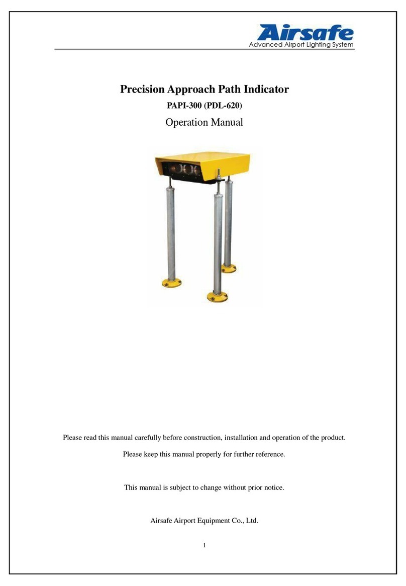
Airsafe PAPI-LED-066 User manual

Advanced Airport Lighting System
1
PrecisionApproach Path Indicator
PAPI-LED-066 / PAPI-LED-220
Operation Manual
Please read this manual carefully before construction, installation and operation of
the product.
Please keep this manual properly for further reference.
This manual is subject to change without prior notice.
Airsafe Airport Equipment Co., Ltd.

Advanced Airport Lighting System
2
Revision Description
No.
Description
Version
No.
Revised by
Approved
by
Date
1
First release
V1.0
Z. H,
H. GT
C. JQ
Jun. 18, 2019
2
Modified 2.7, 3.1, 3.2
V1.1
Z. H
C. SY
Sep. 25, 2020
3
Add S-type installation
method
Modify 3.3.5
Add new section 5.3
Add new section 5.4
Add new section 6.1.4
V1.2
G.JH
Z.H
Z.JC
C.JQ
C.SY
Dec.08,2021

Advanced Airport Lighting System
3
Table of Content
1.0 Foreword.......................................................................................................................................5
1.1 Illustrations and Meanings....................................................................................................6
1.2 Safety Rules and Notices ......................................................................................................7
1.3 Quality Assurance and Responsibility...................................................................................8
2.0 Introduction...................................................................................................................................9
2.1 Technical Specifications......................................................................................................10
2.2 Application Environment ....................................................................................................10
2.3 Application Scope ...............................................................................................................10
2.4 Technical Parameters...........................................................................................................11
2.5 Technical Features...............................................................................................................13
2.6 Structure..............................................................................................................................15
2.6.1 Key Components of Upper Box...............................................................................15
2.6.2 Key Components of Landing Leg Assy ...................................................................16
2.7 Interpretation of System Terminology ................................................................................17
2.7.1 Elevation ..................................................................................................................17
2.7.2 Key Buttons and Plug-ins.........................................................................................17
2.7.3 Two Working Conditions and Four Modes ..............................................................20
2.7.4 Power Supply of PAPI..............................................................................................26
3.0 Installation of Lighting Fixtures..................................................................................................28
3.1 Location of PAPI system.....................................................................................................28
3.2 Boundary Dimension ..........................................................................................................29
3.3 On-site Installation of PAPI Lighting Fixtures....................................................................30
3.3.1 Flange Fixation.........................................................................................................33
3.3.2 Installation of Legs...................................................................................................36
3.3.3 Same Height Setting of Lighting Fixtures................................................................38
3.3.4 System matched power/communication cable selection..........................................41
3.3.5 Electrical Wiring of Lighting Fixtures .....................................................................43
3.3.6 Adjustment and Setting of Lighting Fixture Elevation.............................................47
4.0 Flight Calibration Inspection and Adjustment of Lighting Fixtures ...........................................50
4.1 Disposal after Flight Calibration.........................................................................................51
5.0 Replacement of Components of Lighting Fixtures .....................................................................54
5.1 How to Replace Light Source Assembly.............................................................................55
5.2 How to Replace Main Control Board..................................................................................57
5.3 How to Replace Digital Display Panel................................................................................58
5.4 Replace Terminal Block......................................................................................................60
6.0 Maintenance of Precision Approach Path Indicator....................................................................61
6.1 Daily Inspection and Maintenance......................................................................................61
6.1.1 Daily Inspection and Maintenance Items.................................................................61
6.1.2 Troubleshooting of Common Error of Control Board..............................................63
6.1.3 Inspection Method of Elevation...............................................................................65

Advanced Airport Lighting System
4
6.1.4 Inspection Method of Transverse Horizontal Angle.................................................66
6.2 Troubleshooting of Common Faults....................................................................................69
7.0 List of Components and Ordering of Spare Parts and Accessories.............................................70
8.0 Conversion Table ........................................................................................................................72
9.0 Packaging, Transportation and Storage.......................................................................................73
9.1 Packaging and Weight.........................................................................................................73
9.2 Transportation Mode...........................................................................................................73
9.3 Storage ................................................................................................................................73

Advanced Airport Lighting System
5
1.0 Foreword
ICAO Airport Service Manual Part 9 “Airport Maintenance Practices” and FAA
AC150/5345-26 Maintenance of Airport Visual Aid Facilities are the highest criterions
for site installation and maintenance of such lighting fixtures. This manual was
compiled with considerable reference to these two criterions.
The content stated in this manual is absolutely important, so construction
personnel must read it carefully before construction. After properly understanding the
entire content of this manual, construction personnel should carry out the construction
in strict accordance with the methods specified herein, to ensure that the product is
safely and properly installed in place.
Routine airport maintenance personnel should carry out the routine maintenance
in strict accordance with the methods specified by relevant provisions, to ensure that
the lighting fixtures are in the best operation condition.
Related personnel must strictly follow safety criterion. Any personnel without
specialized training are strictly forbidden to touch the lighting fixtures and devices.
Live line work should be avoided under any circumstances. Construction or
maintenance personnel should get acquainted with first-aid knowledge, in case of any
unexpected events.

Advanced Airport Lighting System
6
1.1 Illustrations and Meanings
○Following illustrations will appear in this manual where necessary to remind
or warn construction or maintenance personnel.
○Please continue reading the subsequent content of this manual after properly
understanding the meanings of these illustrations.
To remind that the behavior may cause serious injury or death.
※Detailed description will be given in the box.
To remind that the behavior may cause injury to people or
damage to product.
※Detailed description will be given in the box.
To notify that the behavior is prohibited.
※Detailed description will be given in the box.

Advanced Airport Lighting System
7
1.2 Safety Rules and Notices
Using the light fixtures outside of airport is strictly prohibited.
※Inadequate maintenance or casual touch will cause light faults.
Be careful when handling the precision approach path indicator.
※Falling to the ground or collision will damage the parts or cause
personal injury.
During installation or maintenance, making sure that the power
source is disconnected.
※The unknown current impact may damage the device
Making sure effective earthing according to the requirements of
the specification.
※Otherwise it may cause electric leakage or shock
Making sure that the constant current is no greater than 6.6A.
※Otherwise it may cause internal electric damage, or even failure
of power supply
There is a frangible groove at the lower part of the landing leg
and great external force shall not be applied during installation.
※Otherwise the frangible groove on the landing leg may be
broken.
Maintenance of the precision approach path indicator by the
non-professional electrician is prohibited.
※Otherwise it may cause electric shock or other personal injuries.
Touching the lighting fixtures with wet hand is strictly
prohibited.
※It may cause electric shock or other accident.
The power source entry or internal electric wire shall be
replaced immediately when it is damaged.
※Otherwise it may cause equipment failure or electric shock.

Advanced Airport Lighting System
8
1.3 Quality Assurance and Responsibility
Any defect in design, material or workmanship, which may occur during proper
and normal use over a period of one year from date of installation but less than 15
months from date of shipment, or within the warranty period of the tender, will be
repaired or preplaced by manufacturer free of charge. The warranty doesn’t cover the
failures resulting from lamp burnt out, improper maintenance, installation or operation,
or damages due to snow ploughs. Manufacturer shall not be liable to any further claims
or particularly claims for damages not affecting the goods themselves.

Advanced Airport Lighting System
9
2.0 Introduction
○Introduction and application
The PAPI system shall consist of a wing bar of four sharp transition multi-lamp
(or paired single lamp) units equally spaced. The system shall be located on the left
side of the runway unless it is physically impracticable to do so.
○Model description
PAPI ---LED--- X ---X --- X
Type 066 PAPI is powered by a constant current regulator. One lamp is equipped
with a 100W / 6.6A isolation transformer, which is installed under the lamp or
separately.
Type 220 PAPI is powered by 220 VAC power supply without isolation
transformer. It can be dimming by monitoring the ambient light intensity through the
light control board.
It is recommended to purchase the PAPI system with monitoring module. The
status and fault information of PAPI system can be accurately fed back to the light
station through the CAN communication cable of the monitoring module, and
information is timely fed back to the monitoring system through 485 standard
communication cable to help the user timely, reliably and efficiently monitor it.
Type
PAPI-LED = LED Precision approach path indicator
Option
R= with Remote Monitoring
(CAN Communication, recommended option)
Power supply
220= Parallel, 220V
066= Series, 6.6A
Installation method
S installation dimension=500*390 (recommended)
P installation dimension=525*460 (apply to PAPI-300)

Advanced Airport Lighting System
10
2.1 Technical Specifications
This product conforms to the provisions of the following standards or technical
specifications. For dated standards or technical specifications, only the edition cited
applies. For undated references, the latest edition of the referenced document
(including any amendments) applies.
Convention on International Civil Aviation Annex 14- Aerodromes Volume I;
International Civil Aviation Organization (ICAO)- Aerodrome Design
Manual- Part 4 & Part 6;
Federal Aviation Administration (FAA) AC150/5345-28;
Department of Airport of Civil Aviation Administration of China: Advisory
Circular, General Technical Requirements for Civil Airport LED Navigation Aid
Lighting Fixtures (AC-137-CA-2015-01-R1)
Department of Airport of Civil Aviation Administration of China, Advisory
Circular, Technical Requirements for Precision Approach Path Indicator
(AC-137-CA-2015-07)
2.2 Application Environment
○Altitude: below 4,500m;
○Outdoor: -40°C ~ +55°C;
○Relative air humidity: not more than 95%;
○In rain, snow, ice and water;
○Expose to corrosive salt atmosphere
○Basic earthquake intensity VII.
2.3 Application Scope
Precision approach path indicator for Category I, II and III airports.
Heliport precision approach path indicator.

Advanced Airport Lighting System
11
2.4 Technical Parameters
Name
Precision approach
path indicator (066)
Precision approach
path indicator(220)
Type
PAPI-LED-066
PAPI-LED-220
Environmental
conditions 1
Inside the light box: ambient temperature >55 ℃, ambient
humidity <45%
Power / remarks
58W/normal operation
Environmental
conditions 2
Inside the light box: ambient temperature <55℃, ambient
humidity <45%
Power / remarks
64W/ normal operation, the additional electric heating module
works
Environmental
conditions 3
Inside the light box: ambient temperature >55 ℃, ambient
humidity>45%
Power / remarks
64W/ normal operation, the additional demisting module works
Environmental
conditions 4
Inside the light box: ambient temperature<55℃ ,ambient
humidity>45%
Power / remarks
71W/ normal operation, additional electric heating & defogging
Using the lighting fixtures beyond the specified scope is strictly
prohibited.
※Application beyond the specified scope will cause damage or
risk to any component.

Advanced Airport Lighting System
12
modules work simultaneously
Light source life
≥100000h (L70)

Advanced Airport Lighting System
13
2.5 Technical Features
•Light distribution and color of the lighting fixtures meet the requirements of
Attachment 14 of ICAO & FAAAC 5345-28.
•Excellent optical system design makes excellent red and white transition of PAPI
with straight transition line.
•Use LED light source, max power consumption at low temperature is less than
72W.
•Intelligent electrical control system can automatically turn off the light in case of
abnormal conditions.
•Each lighting fixture has a 4-digit LED digital tube to timely display the elevation
angle of the lighting fixture with high precision.
•Slight changes in lateral horizontal angle can be displayed through LED
indicators.
•The unit controller achieves one key operation, easy to operate and master.
•“Operation” and “Calibrate Flight” are set for the control panel for easier use.
•No condensation design ensures that there is no abnormal light output of lamps on
the windshield in wet and dew weather
•The data of LED PAPI system can be uploaded to ALCMS directly with matched
communication module.
•Compact overall structure with small windward area and strong wind resistance.
•The main body of the light fitting is made of corrosion-resistant aluminum alloy
with anti-corrosion surface treatment. All fasteners are made of stainless steel,
suitable for various harsh environments.
•The aluminum alloy leg has the frangible function. After precision mechanical
processing, it complies with the requirements of FAA, with stable and reliable
performance.
•IP66-grade ingress protection of the lighting fixture, which could keep interior
from dust and rain.

Advanced Airport Lighting System
14
•Three leg type horizontal support and height adjustment structure for convenient
and accurate on-site installation and adjustment.
•Equipped with independent level in horizontal and longitudinal direction for
convenient installation and maintenance.
•The maximum windward area of the lighting fixture is 0.48m².
•The external plug of the lamp is A6 double core plug, which meets the
requirements of FAA AC 5345-26, and matches with the output lead of isolation
transformer.

Advanced Airport Lighting System
15
2.6 Structure
2.6.1 Key Components of Upper Box
Power supply 6.6A Power supply 220V
Common parts of power supply 6.6A and 220V:
1. Upper cover plate assy.
2. Optical lens assy.
3. Horizontal indicator
4. Digital display board
5. Longitudinal indicator
6. Refrigeration module
7. Seal pressing bracket
8. Glass sealing ring
9. Front glass
10. Box
11. Driver
12. Hose connector
14. Hasp
15. Bracket
16. Terminal block
17. LED light source assy
18. Light source holder
Spare parts of 6.6A
power supply:
13. Transformer
Spare parts of 220V power
supply:
19. Switch power supply
20.Optical control circuit board
21. Optical control module

Advanced Airport Lighting System
16
2.6.2 Key Components of Landing Leg Assy
1. Flange
2. Landing leg
3. Front cover of landing leg
4. Tapping screw ST5.5
5. Spring washer 16
6. Screw stem
7. Hex nut M16
8. Hex thin nut M16
9. Lower spherical washer
10. Upper spherical washer
11. Wave spring washer 16

Advanced Airport Lighting System
17
2.7 Interpretation of System Terminology
2.7.1 Elevation
The beam centers of all lighting fixtures in the PAPI system aim at the approach
slope according to the defined subtle deviation and the elevation means the included
angle of the beam center of the lighting fixtures and the horizontal plane.
2.7.2 Key Buttons and Plug-ins
The general framework of the PAPI control panel is shown in Figure below and
definitions of the key buttons and plug-ins are as follows:
J1: Power input socket of Type 066 PAPI
J2: CAN communication and power input socket of type 220 PAPI
J15: Sub-plate socket
J11: LED Light source socket
SW2: Dial switch, which is used to set CAN address
SW1: Mode switching button, which is used to switch between state modes
J13: Light control plate socket
Users are prohibited to switch SW2 in their daily use. It’s only needed to switch

Advanced Airport Lighting System
18
SW2 and set the system to Factory Setup Status when setting CAN address or
replacing the control plate.
The PAPI system has four lamps, each with a different address, which can be
configured as 1, 2, 3, 4, 5, 6, 7, 8. The eight addresses are divided into two groups, 1, 2,
3, 4 as one group and 5, 6, 7, 8 as the other group. When a lamp is abnormal, other
lamps in the same group will be linked, not lamps in the different group.
Setting the address to 0.9 is prohibited in daily use unless you want to enter the
factory setup state. When the address is set to 0.9, the lamp will turn off to remind the
user to set the address correctly.
The overall framework of the PAPI display panel is shown in the following figure.
The main plug-ins in the diagram is defined as follows:
DS1: Four-digit digital tube.
Four-digit Digital tube: There is a four-digit digital tube embedded on the PAPI
control panel (as shown in Figure DS1 above), which timely displays the current mode
and elevation of PAPI. The angle displayed by the digital tube has four characters, with
the first character of a letter, showing the mode of PAPI and the last three characters
showing the “current angle”.
Display under “Calibrate Flight”Display under “Operation”

Advanced Airport Lighting System
19
Display under “Store”Display under “Error”

Advanced Airport Lighting System
20
2.7.3 Two Working Conditions and Four Modes
This PAPI system has two working conditions and four modes, whose relations
are shown in Figure below:
工厂设置
状态
运行模式
A
用户设置
状态
校飞模式
C
当SW2地址为9
的前2秒内SW1
点击5次
包含 包含
SW2地址不为9
错误模式
E
存储模式
F
系统异常
按时切换
显示
当前角度
和
存储角度
长按SW1
保存
当前角度
点按SW1
按时切换
显示
当前角度
和
存储角度
When the "User Mode" of PAPI is switched to "Factory Mode", user should set
address SW2 to 9 first, and press SW1 quickly for 5 times within the first 2 seconds to
achieve the switch.
The "Factory Mode" of PAPI can be switched to "User Mode" when the address
SW2 is not 9.
On “User Mode”, click “SW1”to switch between “Calibrate Flight Mode” and
“Operation Mode”. Long press "SW1" for more than 5 seconds to enter the “Store
Mode”and store the current angle.
Generally, the system is under the “Operation Mode”and “Store Mode”, and the
mode switches on time, with a cycle of every 5 seconds. The current angle is displayed
User
Mode
SW2 Address is not 9
Calibrate
Mode
Click on SW1
Include
Press SW1 for 5
times within the
first two seconds
when SW2 address
is 9
Include
Operation “A”
Error “E”
System abnormal
Long press
SW1 to store
the current
angle
Store “F”
Display current
angle and stored
angle in turn
Display current
angle and
stored angle in
turn
Factory
Mode
This manual suits for next models
1
Table of contents
Other Airsafe Measuring Instrument manuals
Popular Measuring Instrument manuals by other brands

Aquametro
Aquametro AMTRON X-50 Mounting and operating instructions

Phase Technologies
Phase Technologies PHASE CONNECT PC4R Installation & operation manual

AimTTi
AimTTi PSA1303 quick start guide

Global Test Supply
Global Test Supply DOUBLE VISION DDPM-40 quick start guide

KEPCO
KEPCO RTP Installation & operating instructions

AutoMeter
AutoMeter RC-300 Operator's manual