TECHNICAL DATA
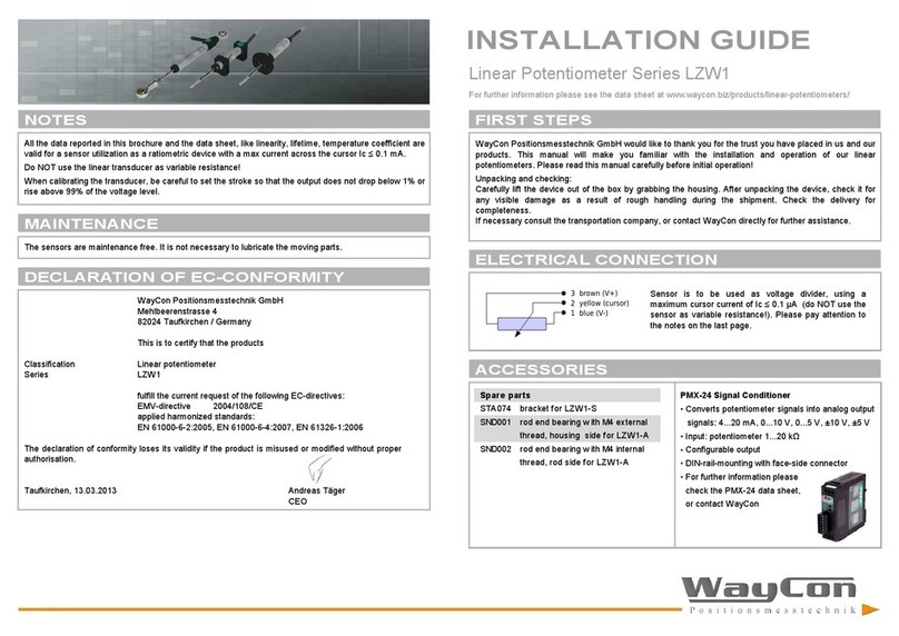
INSTALLATION GUIDE
Linear potentiometer Series LRW2, LRW3
For further information please see the ata sheet at www.waycon.biz/pro ucts/linear-potentiometers/
TECHNICAL DRAWING
Useful electrical stroke B: correspon s to the sensors measurement range
Theoretical electrical stroke C: actual length of the con uctive path, that has to be longer than B, in or er
to get a vali electrical signal at the start an en point of the measurement range.
When calibrating the trans ucer, be careful to set the stroke so that the output oes not rop below 1%
or rise above 99% of the voltage level.
ACCESSORIES
LRW2-C wit ball tip and connector output
LRW3-C wit roller tip and connector output
LRW2-F, LRW3-F wit cable output
CON011: mating connector for LRW2-C, LRW3-C
for self assembly,
IP40, 5 pole,
cable iameter 4...6 mm
Spare parts
PTAS000 spare ball tip
(LRW2: inclu e in elivery)
PTAS001 spare roller tip
(LRW3: inclu e in elivery)
PKIT005 mounting kit brackets
(LRW2, LRW3: inclu e in elivery)
Usef ul electrical stroke (B) +1/-0 [mm] 10 25 50 75 100 150
Theoretical electrical stroke (C) ±1 [mm] B + 1
Resistance 1 1 5 5 5 5
Linearity [%] ±0.3 ±0.2 ±0.1 ±0.1 ±0.1 ±0.05
Dissipation at 40°C (0 W at 120 °C) [W] 0.2 0.6 1.2 1.8 2.4 3.6
Maximum applicable v oltage [V] 14 25 60 60 60 60
Mechanical stroke (D) [mm] B + 5
Case length (A) [mm] B + 38
Tip length (E) LRW2 [mm] 32 32 40 40 40 40
Tip length (E) LRW3 [mm] 43 43 51 - - -
Total length LRW2 [mm] 108 138 196 251 307 426
Total length LRW3 [mm] 119 149 207 - - -
[kOhm]
PMX-24 Signal Conditioner
• Converts potentiometer signals into analog output
signals: 4...20 mA, 0...10 V, 0...5 V, ±10 V, ±5 V
• Input: potentiometer 1...20 kΩ
• Configurable output
• DIN-rail-mounting with face-si e connector
• For further information please
check the PMX-24 ata sheet,
or contact WayCon


