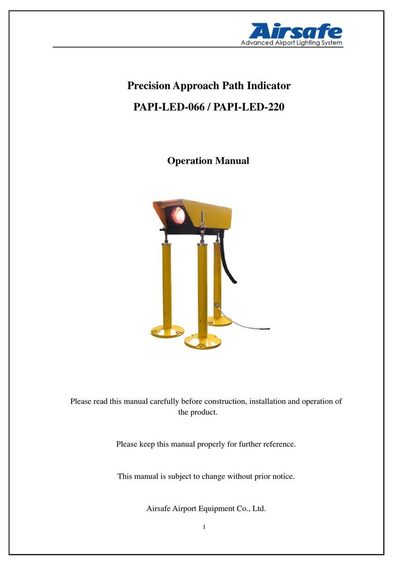
Airsafe PAPI-300 User manual

Advanced Airport Lighting System
1
Precision Approach Path Indicator
PAPI-300 (PDL-620)
Operation Manual
Please read this manual carefully before construction, installation and operation of the product.
Please keep this manual properly for further reference.
This manual is subject to change without prior notice.
AirsafeAirport Equipment Co., Ltd.

Advanced Airport Lighting System
2
Revision Description
No.
Description
Version No.
Revised by
Approved
by
Date
1
First release
V1.0
Y. YH
C. SY
Apr. 10, 2008
1
Gateway contents added
and composing adjusted
V1.1
ZH and G. JH
X. CL
Nov. 20, 2016

Advanced Airport Lighting System
3
Table of Content
1.0 Foreword......................................................................................................................................5
1.1 Illustrations and Meanings.................................................................................................5
1.2 Safety Rules and Notices.....................................................................................................6
1.3 Quality Assurance and Responsibility...............................................................................7
2.0 Introduction.................................................................................................................................8
2.1 Technical Specifications......................................................................................................9
2.2 Application Environment ...................................................................................................9
2.3 Application Scope................................................................................................................9
2.4 Technical Parameters..........................................................................................................9
2.5 Technical Features.............................................................................................................10
2.6 Structure ............................................................................................................................11
2.6.1 Key Components of Upper Box.............................................................................11
2.6.2 Key Components of Landing Leg Assy ................................................................12
2.7 Interpretation of System Terminology ............................................................................13
2.7.1 Elevation..................................................................................................................13
2.7.2 Key Buttons and Plug-ins......................................................................................14
2.7.3 Two Working Conditions and Four Modes..........................................................16
3.0 Installation of Lighting Fixtures..............................................................................................22
3.1 Position of PAPI andAPAPI system................................................................................22
3.2 Boundary Dimension ........................................................................................................23
3.3 On-site Installation of PAPI Lighting Fixtures...............................................................24
3.3.1 Flange Fixation.......................................................................................................24
3.3.2 Installation of Landing Leg...................................................................................26
3.3.3 Same Height Setting of Lighting Fixture Set .......................................................27
3.3.4 Electrical Wiring of Lighting Fixtures .................................................................29
3.3.5 Adjustment and Setting of Lighting Fixture Elevation.......................................33
4.0 Flight Calibration Inspection andAdjustment of Lighting Fixtures....................................35
4.1 Disposal after Flight Calibration.....................................................................................36
5.0 Replacement of Components of Lighting Fixtures.................................................................38
5.1 How to Replace Lamp.......................................................................................................39
5.2 How to Replace Filter.......................................................................................................41
5.3 How to Replace Control Panel .........................................................................................42
6.0 Maintenance of PrecisionApproach Path Indicator..............................................................44
6.1 Daily Inspection and Maintenance ..................................................................................44
6.1.1 Daily Inspection and Maintenance Items.............................................................44
6.1.2 Troubleshooting of Common Error of Control Panel .........................................46
6.1.3 Inspection Method of Elevation ............................................................................47
6.2 Troubleshooting of Common Faults ................................................................................48
7.0 List of Components and Ordering of Spare Parts andAccessories......................................49
8.0 °-〃Conversion Table..............................................................................................................51

Advanced Airport Lighting System
4
9.0 Packaging, Transportation and Storage..................................................................................52
9.1 Packaging and Weight ......................................................................................................52
9.2 Transportation Mode........................................................................................................52
9.3 Storage................................................................................................................................52

Advanced Airport Lighting System
5
1.0 Foreword
ICAO Airport Service Manual Part 9 “Airport Maintenance Practices” and FAA
AC150/5345-26 Maintenance of Airport Visual Aid Facilities are the highest criterions
for site installation and maintenance of such lighting fixtures. This manual was
compiled with considerable reference to these two criterions.
The content stated in this manual is absolutely important, so construction
personnel must read it carefully before construction. After properly understanding the
entire content of this manual, construction personnel should carry out the construction
in strict accordance with the methods specified herein, to ensure that the product is
safely and properly installed in place.
Routine airport maintenance personnel should carry out the routine maintenance
in strict accordance with the methods specified by relevant provisions, to ensure that
the lighting fixtures are in the best operation condition.
Related personnel must strictly follow safety criterion. Any personnel without
specialized training is strictly forbidden to touch the lighting fixtures and devices. Live
line work should be avoided under any circumstances. Construction or maintenance
personnel should get acquainted with first-aid knowledge, in case of any unexpected
events.
1.1 Illustrations and Meanings
○Following illustrations will appear in this manual where necessary to remind or warn
construction or maintenance personnel.
○Please continue reading the subsequent content of this manual after properly understanding
the meanings of these illustrations.
To remind that the behavior may cause serious injury or death.
※Detailed description will be given in the box.
To remind that the behavior may cause injury to people or damage to product.
※Detailed description will be given in the box.
To notify that the behavior is prohibited.
※Detailed description will be given in the box.

Advanced Airport Lighting System
6
1.2 Safety Rules and Notices
Using the light fixtures outside of airport is strictly prohibited.
※Inadequate maintenance or casual touch will cause light faults.
Be careful when handling the precision approach path indicator.
※Fall to the ground or collision will damage the parts or cause
personal injury.
During installation or maintenance, making sure that the power
source is disconnected.
※The unknown current impact may damage the device
Making sure effective earthing according to the requirements of the
specification.
※Otherwise it may cause electric leakage or shock
Making sure that the constant current is no greater than 6.6A.
※Otherwise it may cause internal electric damage, or even failure of
power supply
There is a frangible groove at the lower part of the landing leg and
great external force shall not be applied during installation.
※Otherwise the frangible groove on the landing leg may be broken.
Maintenance of the precision approach path indicator by the
non-professional electrician is prohibited.
※Otherwise it may cause electric shock or other personal injuries.
Touching the lighting fixtures with wet hand is strictly prohibited.
※It may cause electric shock or other accident.
The power source entry or internal electric wire shall be replaced
immediately when it is damaged.
※Otherwise it may cause equipment failure or electric shock.

Advanced Airport Lighting System
7
1.3 Quality Assurance and Responsibility
Any defect in design, material or workmanship, which may occur during proper
and normal use over a period of one year from date of installation but less than 15
months from date of shipment, or within the warranty period of the tender, will be
repaired or preplaced by manufacturer free of charge. The warranty doesn’t cover the
failures resulting from lamp burnt out, improper maintenance, installation or operation,
or damages due to snow ploughs. Manufacturer shall not be liable to any further claims
or particularly claims for damages not affecting the goods themselves.

Advanced Airport Lighting System
8
2.0 Introduction
This manual involves the following series lighting fixtures:
PAPI-300------------------------Precision Approach Path Indicator
PAPI-300-R----------------------Precision Approach Path Indicator (with Remote
Monitoring)
Type of Precision Approach Path Indicator (PAPI-300):
Type of Precision Approach Path Indicator (with Remote Monitoring)
(PAPI-300-R):
PAPI is equipped a 300W/6.6A isolation transformer, which is installed under the
lamp or additional separated position.
PAPI system (PAPI-300-R) with the monitoring module is suggested, whose
system state and failure information may be fed back to the lamplight station through
the CAN communication cable of the monitoring module and information is timely fed
back to the monitoring system through 485 standard communication cable to help the
user timely, reliably and efficiently monitor it.
Type
PAPI-300= precision approach path indicator
Type
PAPI-300= precision approach path indicator
with remote monitoring

Advanced Airport Lighting System
9
2.1 Technical Specifications
This product conforms to the provisions of the following standards or technical
specifications. For dated standards or technical specifications, only the edition cited
applies. For undated references, the latest edition of the referenced document
(including any amendments) applies.
International Electrotechnical Commission (IEC) TS 61827;
Convention on International Civil Aviation Annex 14- Aerodromes Volume 1;
International Civil Aviation Organization (ICAO)- Aerodrome Design Manual-
Part 4: Visual Aids;
Federal Aviation Administration (FAA) AC150/5345-46;
Federal Aviation Administration (FAA) EB 67;
GB/T 7256 General Requirements of Lighting Fixtures for Civil Airport;
Department of Airport of Civil Aviation Administration of China: Advisory
Circular, Technical Requirements for Runway and Taxiway Aid Lighting Fixtures
(AC-137-CA-2015-03)
Department of Airport of Civil Aviation Administration of China, Advisory
Circular, General Technical Requirements for Civil Airport LED Aid Lighting
Fixtures (AC-137-CA-2015-01)
2.2 Application Environment
○Altitude: below 4,000m;
○Outdoor: -55°C ~ +55°C;
○Relative air humidity: not more than 95%;
○In rain, snow, ice and water;
○Expose to corrosive salt atmosphere
○Basic earthquake intensity VII.
2.3 Application Scope
Precision approach path indicator for Category I, II and III airports.
Using the lighting fixtures beyond the specified scope is strictly prohibited.
※Application beyond the specified scope will cause damage or risk to any
component.
2.4 Technical Parameters
Description
Type
Rated Power
Life of light source at 6.6A
Precision approach path indicator
PAPI-300
3×10⁵W
≥1,000h

Advanced Airport Lighting System
10
2.5 Technical Features
•Grading and color of the lighting fixtures meet the requirements of Attachment 14
of ICAO;
•Proprietary optical system design makes excellent red and white transition of PAPI
and straight transition line;
•Optical parts have self-positioning design and recalibration is unnecessary for
replacing the optical components and lamp;
•The filter employs advanced coating technology, with high light transmittance,
firm coating and good thermostability;
•A heater strip built in the front windshield may remove the condensation, which
does not impact the luminous effect of the lighting fixtures;
•Intelligent electric control system may make PAPI automatically turn off the light
in case of abnormal cases;
•Each lighting fixture has a 4-digit LED Nixie tube to timely display the elevation
of the lighting fixture with high precision;
•The unit controller may be operated through one key, which is easily operated and
conveniently mastered;
•“Operation”and “Calibrate Flight”are set for the control panel for easier use;
•The open-circuit monitoring function makes the system more reliable and safer;
•The optional communication module may make the data of the PAPI system to be
directly uploaded to the monitoring system;
•The lighting fixtures have a compact structure, attractive appearance, small face
area and high wind loading rating;
•Main body of the lighting fixtures is made of aluminum alloy material with special
anodizing surface treatment, and all fasteners are made of stainless steel, thus
being applicable to all kinds of harsh environment;
•The landing leg made of the aluminum alloy has the frangible function. After
precision mechanical processing, it complies with the requirements of FAA, with
stable and reliable performance;
•The energy consumption of 3 105W reflector lamps is only half that of the
traditional PAPI;
•Sealing design of the lighting fixtures makes water and dust entry impossible;
•Three landing leg type horizontal support and height adjusting mechanism make
on-site PAPI installation and calibration convenient and accurate;
•Independent level gauges are set horizontally and vertically for the lighting
fixtures for easy installation and maintenance;

Advanced Airport Lighting System
11
2.6 Structure
2.6.1 Key Components of Upper Box
1. Upper cover plate assy
2. Dust cover plate
3. Seal pressing bracket
4. Front glass (assy)
5. Box
6. Temperature controlled switch
7. Transformer
8. Longitudinal level module
9. Front glass set
10. Filter disc
11. Compressed spring
12. Rear glass set
13. Circuit board
14. Thermal insulation box
15. Lamp mounting plate
16. Wire holder
17. Lamp
18. Drive assy
19. Hose coupler
20. Electric wire set
21. Junction box

Advanced Airport Lighting System
12
2.6.2 Key Components of Landing Leg Assy
1. Flange
2. Landing leg
3. Front cover of landing leg
4. Tapping screw ST5.5
5. Spring washer 16
6. Screw
7. Hex nut M16
8. Hex thin nut M16
9. Lower washer of sphere
10. Upper washer of sphere
11. Wave spring washer 16

Advanced Airport Lighting System
13
2.7 Interpretation of System Terminology
2.7.1 Elevation
The beam centers of all lighting fixtures in the PAPI system aim at the approach
slope according to the defined subtle deviation and the elevation means the included
angle of the beam center of the lighting fixtures and the horizontal plane.

Advanced Airport Lighting System
14
2.7.2 Key Buttons and Plug-ins
The general framework of the PAPI control panel is shown in Figure below and
definitions of the key buttons and plug-ins are as follows:
SW1: Setting state switching jumper cap (switching between “Factory Mode”and
“User Mode”);
SW2: Mode switching button (switching between “Operation” and “Calibrate
Flight”);
J3: Main power source and light source receptacle;
J5: CAN adapter plate receptacle;
DS1: Four-digit Nixie tube.
SW1: Setting state switching jumper cap, which is used for switching between
“Factory Mode” and “User Mode”;
SW2: Mode switching button, which is used for switching between different state
modes under “User Mode”;
Rightmost J5 on the control panel is an interface reserved for CAN adapter plate,
through which the data of the control panel may be transmitted to the monitoring
system. J3 near the middle is a key connector, through which all power cables, power
source cables and buses are connected with the external cables.
Operation + (Real Angle)
Calibrate Flight+ (Real
Angle)
Error + (RealAngle)
Memory complete+
(Memory Angle)

Advanced Airport Lighting System
15
After this system is powered on, the panel control will automatically enter
“Operation”and have the function to automatically recover “Operation” with
unmanned operation under “Calibrate Flight” to prevent misoperation by the airport
personnel.
Four-digit Nixie tube: There is a four-digit Nixie tube embedded on the PAPI
control panel (as shown in Figure DS1 below), which timely displays the current
mode and elevation of PAPI. The angle displayed by the Nixie tube has four
characters, with the first character of a letter, showing the state of PAPI and the last
three characters showing the “current angle”.
Display under “Calibrate Flight”Display under “Operation”
Display under “Memory Angle” Display under “Error”
Operation + (RealAngle)
Calibrate Flight+
(Real Angle)
Error + (RealAngle)
Memory complete+
(MemoryAngle)

Advanced Airport Lighting System
16
2.7.3 Two Working Conditions and Four Modes
This PAPI system has two working conditions and four modes, whose relations
are shown in Figure below:
“Factory Mode” and “User Mode” of PAPI are switched through SW1.
(1) “Factory Mode”:
When PAPI is in “Factory Mode”, the Nixie tube only displays the current angle.
“Factory Mode” is only used for the standard calibration of PAPI when it leaves the
factory, or clearing the angle when the control panel of PAPI is replaced. During daily
normal use, the user shall not enter “Factory Mode”. Otherwise, the Nixie tube will
reset and “Memory Angle” of the system will be automatically cleared, as shown in
Figure below:
Display under “Factory Mode”
■ Switching SW1 randomly is strictly prohibited.
※To enter the Factory Mode may cause loss of data in the PAPI
system.
■ Metal articles close to SW1 is strictly prohibited.
※Otherwise it may cause automatic trigger of SW1, resulting in loss
of data in the PAPI system.
Factory mode
Operation
“A”
User mode
Calibrate
Flight “C”
Switched through SW1
jumper cap
Including Including
Switched through
SW2 button

Advanced Airport Lighting System
17
(2) “User Mode”:
When PAPI leaves the factory, the system is in “User Mode” and PAPI executes
various operations.
“User Mode” includes “Calibrate Flight” and “Operation”, which are fixed
programs of the lighting fixtures. Under “User Mode”, SW2 is used for switching of
various modes and the user may switch “Calibrate Flight” and “Operation” through
SW2.
Under “User Mode”, the PAPI system may have “Error” under certain state. After
PAPI enters “Error”, the system will automatically turn off the lamp.
Under “User Mode”, the PAPI system support stores the current angle into the
system and displays the “Memory Angle” through the Nixie tube.
During daily use, the user shall not switch the jumper cap of SW1. SW1 shall be
switched only when the user replaces the control panel and the system shall be set to
“Factory Mode”.
Display under “Calibrate Flight”Display under “Operation”

Advanced Airport Lighting System
18
(3) “Calibrate Flight”
During flight calibration or daily maintenance, the system shall set PAPI to
“Calibrate Flight”. Under this mode, PAPI will not have “Error”, but turn off the lamp
to ensure normal on-going flight calibration or maintenance. The display method of the
four-digit Nixie tube is 4 characters initiated by the letter C (the Nixie tube displays
“C+ value of the current elevation”), with the display shown in Figure below:
Display under “Calibrate Flight”
The above-mentioned Nixie tube information means that PAPI is in “Calibrate
Flight” and the current angle is 2.58.
Under this mode, the angle displayed by the Nixie tube is immediate. When the
real angle of PAPI has any subtle change, the angle of the Nixie tube will be changed
accordingly.
“Calibrate Flight” will automatically recover to Operation after 8h with unmanned
operation to prevent misoperation by the airport personnel.

Advanced Airport Lighting System
19
(4) “Operation”
After this system is powered on, the control panel will automatically enter
“Operation”.
Under “Operation”, PAPI works normally and achieves control of various states,
including such preset functions as error alarm. Therefore, after the flight calibration or
daily maintenance is completed, PAPI is switched to “Operation” from “Calibrate
Flight” through the SW2 button. The display method of the four-digit Nixie tube is 4
characters initiated by the letter A (the Nixie tube displays “A+ value of the current
elevation”), with the display shown in Figure below:
Display under “Operation”
The above-mentioned Nixie tube information means that PAPI is in “Operation”
and the current angle is 2.58.
Under this mode, the angle displayed by the Nixie tube is immediate. When the
real angle of PAPI has any subtle change, the angle of the Nixie tube will be changed
accordingly.
■ PAPI must be set to “Operation” for work.
※PAPI cannot achieve error alarm.
It must be recorded and the user shall record this value in the relevant document
according to the provisions.

Advanced Airport Lighting System
20
(5) “Memory Angle”:
Press the SW2 button for longer than 5s to store the current angle confirmed
through flight calibration into the PAPI system. We call the angle stored into the
system “MemoryAngle”.
The expression form of “Memory Angle” is four characters initiated by the letter
F displayed by the four-digit Nixie tube (the Nixie tube displays “F+ currently memory
angle”):
Display under “Memory Angle”
The above-mentioned Nixie tube information displays “Memory Angle” and the
angle recorded into the system is 2.50.
When the PAPI under “Operation”, the Nixie tube alternately displays the current
angle and memory angle with 5s as a circle. It displays the “Memory Angle” at 2s and
“Current Angle” at 3s. The user may understand the difference between the current
real angle of PAPI and previously memory angle of the flight calibration.
For example, the current operating angle is “A2.58”. When the current “Memory
Angle” (design angle) is “F2.50”, the Nixie tube will display the following two legends
alternately:
Display at 2s
Display at 3s
These two data are displayed alternately under “Operation”.
Take the above-mentioned Figures as examples, although the difference between
the current operating angle and the current memory angle is 0.08°, it is still within the
allowable range and PAPI will not have any action.
■ As an important datum, the “Memory Angle” shall not be
changed randomly.
※Otherwise it may cause PAPI have no standard, so as to
generate misoperation.
This manual suits for next models
1
Table of contents
Other Airsafe Measuring Instrument manuals