AirStage UTY-RNK Series User manual

P/N9373329169-03
OPERATING MANUAL
AIR CONDITIONER
Remote Controller
UTY-RNK
REMOTE CONTROLLER
(WIRED TYPE)
TM
English
Deutsch
Français
Español
Italiano
EλληvIkά
Русский
Português
OPERATING MANUAL
BEDIENUNGSANLEITUNG
MODE D’EMPLOI
MANUAL DE FUNCIONAMIENTO
MANUALE DI ISTRUZIONI
ΕΓΧΕΙΡΙ∆ΙΟ ΛΕΙΤΟΥΡΓΙΑΣ
РУКОВОДСТВО ПО ЭКСПЛУАТАЦИИ
MANUAL DE INSTRUÇÕES
KEEP THIS MANUAL FOR FUTURE REFERENCE
DIESE ANLEITUNG BITTE SORGFÄLTIG AUFBEWAHREN
CONSERVEZ CE MODE D’EMPLOI AFIN DE POUVOIR VOUS Y RÉFÉRER ULTÉRIEUREMENT
GUARDE ESTE MANUAL PARA PODERLO CONSULTAR EN EL FUTURO
CONSERVARE QUESTO MANUALE PER OGNI EVENTUALE FUTURO RIFERIMENTO
ΚΡΑΤΗΣΤΕ ΤΟ ΕΓΧΕΙΡΙ∆ΙΟ ΓΙΑ ΜΕΛΛΟΝΤΙΚΗ ΑΝΑΦΟΡΑ
СОХРАНИТЕ НАСТОЯЩЕЕ РУКОВОДСТВО ДЛЯ БУДУЩИХ ССЫЛОК
GUARDE ESTE MANUAL PARA CONSULTA POSTERIOR
FUJITSU GENERAL LIMITED
9373329169-03_OM_cover1.p65 4/24/09, 1:54 PM1

En-1
SAFETY PRECAUTIONS
• The “SAFETY PRECAUTIONS” indicated in the operating manual contain important information pertaining to your safety.
Be sure to observe them.
• For details of the operation methods, refer to the operating manual.
• Request the user to keep the manual on hand for future use, such as for relocating or repairing the unit.
CONTENTS
SAFETY PRECAUTIONS................................................ 1
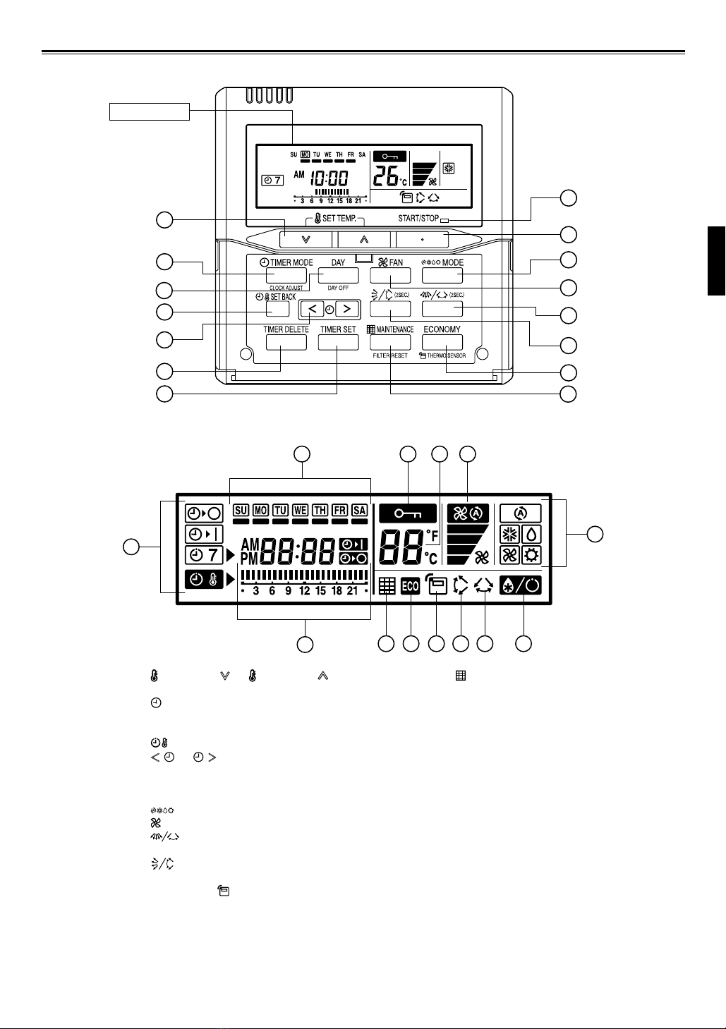
NAME OF PARTS ........................................................... 2
PREPARATION ............................................................... 3
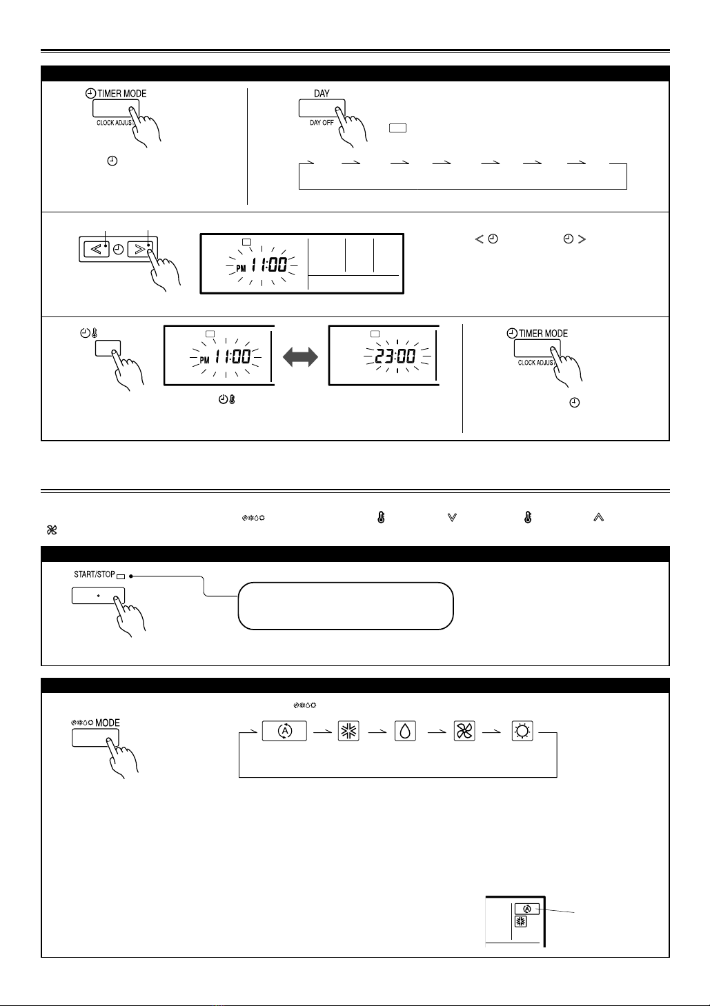
OPERATION ................................................................... 3
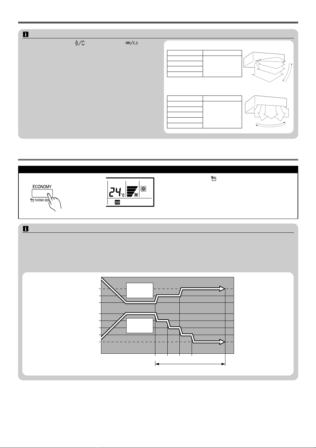
ECONOMY OPERATION ................................................ 5
FILTER LAMP RESET ..................................................... 7
ON/OFF TIMER............................................................... 7
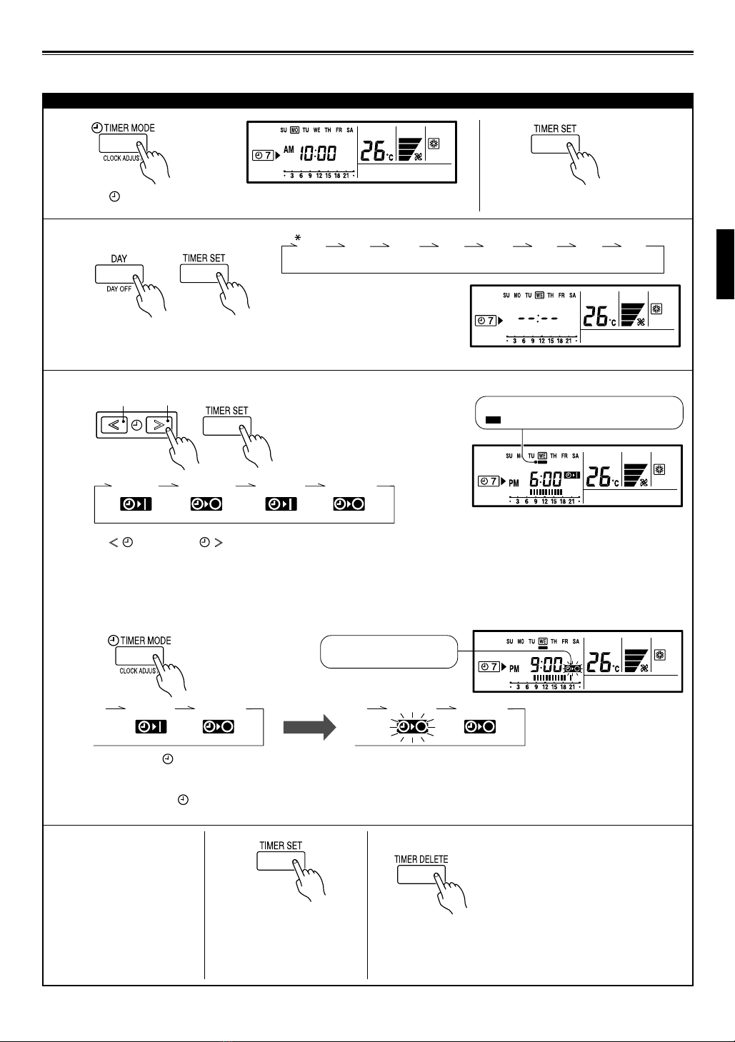
WEEKLY TIMER ............................................................. 8
TEMPERATURE SET BACK TIMER ............................. 10
OPERATING TIPS ......................................................... 11
TROUBLESHOOTING .................................................. 11
SPECIFICATIONS ......................................................... 11
ERROR CODE DISPLAY ............................................... 12
WARNING This mark indicates procedures which, if improperly performed, might lead to the death or serious
injury of the user.
• In the event of a malfunction (burning smell, etc.), im-
mediately stop operation, turn off the electrical breaker,
and consult authorized service personnel.
• Do not repair or modify any damaged cable by your-
self. Let the authorized service personnel to do it. Im-
proper work will cause a electric shock or a fire.
• This unit contains no user-serviceable parts. Always
consult authorized service personnel for repairs.
• When moving, consult authorized service personnel for
disconnection and installation of this unit.
CAUTION This mark indicates procedures which, if improperly performed, might possibly result in personal harm
to the user or damage to property.
• Do not set vessels containing a liquid on this unit. Do-
ing so will cause heating, fire, or electric shock.
• Do not expose this unit directly to water. Doing so will
cause trouble, electric shock, or heating.
• Dispose of the packing materials safely. Tear and dis-
pose of the plastic packing bags so that children can-
not play with them. There is the danger of suffocation
if children play with the original plastic bags.
• Do not place electrical devices within 1 meter of this
unit. It may cause malfunction or failure.
•
Do not use fire near this unit or place a heating appara-
tus nearby. It may cause malfunction.
• Do not touch the switches with sharp objects. Doing
so will cause injury, trouble, or electric shock.
• Do not insert articles into the slit parts of this unit. Do-
ing so will cause trouble, heating, or electric shock.
• Do not touch with wet hands. It may cause an electric
shock.
• If children may approach the unit, take preventive
measures so that they cannot reach the unit.
• Do not repair or modify by yourself. It may cause a fault
or accident.
• Do not use flammable gases near the unit. It may cause
a fire from leaking gas.
9373329169-03_OM_en.p65 5/28/09, 2:15 PM1

En-2
NAME OF PARTS
● With cover open
● Display panel
1“SET TEMP. ”, “ SET TEMP. ”
(Set Temperature Button)
2“TIMER MODE / CLOCK ADJUST”
(Timer Mode/Clock Adjust Button)
3“DAY / DAY OFF” (Day/Day OFF Button)
4“SET BACK” (Set Back Button)
5“”, “ ” (Set Time Button)
6“TIMER DELETE” (Timer Delete Button)
7“TIMER SET” (Timer Set Button)
8“START / STOP” (Start/Stop Button)
9“MODE” (Mode Button)
0“FAN” (Fan Control Button)
A“” (Horizontal airflow direction and swing
Button)
B“” (Vertical airflow direction and swing
Button)
C“ECONOMY / THERMO SENSOR”
(Economy/Thermo Sensor Button)
16 17 18 19
20
21
22 26
24 25
23 27 28
1
2
3
4
5
6
7
8
9
10
11
12
13
14
15
Display panel
D“MAINTENANCE / FILTER RESET”
(Maintenance/Filter Reset Button)
EOperation Lamp
FDay Display
GOperation Lock Display
HTemperature Display
IFan Speed Display
JTimer Mode Display
KOperation Mode Display
LTimer and Clock Display
MFilter Display
NEconomy Display
OThermo Sensor Display
PVertical Swing Display
QHorizontal Swing Display
RDefrost Display
9373329169-03_OM_en.p65 5/22/09, 7:30 PM2

En-3
PREPARATION
To set the operation mode
OPERATION
Instructions related to heating are applicable to “HEAT PUMP MODELS” and “HEAT RECOVERY MODELS” only.
Preset values are displayed when the “ MODE” button, the “ SET TEMP. ” button or “ SET TEMP. ” button, the
“FAN” button is pressed while stopping.
To start/stop operation
Press the “ TIMER MODE / CLOCK
ADJUST” button for 2 seconds or
more. The time display on the remote
controller will flash.
2
SU MO TU WE TH FR SA
Press the “DAY / DAY OFF” button and select the current
day.
A appears around the selected day.
Press the “ ” button or “ ” button to set
the current time.
Press repeatedly to adjust the current time in 1-
minute increments. Press and hold to adjust the
current time in 10-minute increments.
ex. Monday PM11:00
Press the “ TIMER MODE /
CLOCK ADJUST” button
again to end.
1
3
5
Operation lamp
Air conditioner ON: Lit brightly
Air conditioner OFF: Not lit
Press the “START / STOP” button.
Press the “ MODE” button to select the operation mode.
Blinking of START/STOP LED means occurrence of an error. Please refer to “ERROR
CODE DISPLAY” in the manual.
To set the current day and time
● Operation mode setting
* A heat pump model that is not set up as an Administrative Indoor Unit cannot operate in the AUTO mode.
** FAN cannot be selected for a heat pump model.
Refer to details in the Administrative Indoor Unit OPERATING TIPS.
• If the priority mode is set to “Priority on Administrative Indoor Unit”, the operating mode of other indoor units except
Administrative Indoor Unit will be controlled by an Administrative Indoor Unit.
• If the operating mode of Administrative Indoor Unit is set to “AUTO”, “AUTO” is displayed in addition to the display of
current operating mode on other wired remote controllers except Administrative Indoor Unit. In this case, operation of
other indoor units is controlled by the Administrative Indoor Unit.
Example: When operating mode of the Administrative Indoor Unit is set to
“AUTO” while air conditioning setting. (The indication on other
wired remote controllers except Administrative Indoor Unit). When Administrative
Indoor Unit is set to
“AUTO”.
Press the “ SET BACK” button to switch between
the 12- and 24-hour time displays.
4
(SUN) (MON) (TUE) (WED) (THU) (FRI) (SAT)
SU
MO
TU
WE
TH FR
SA
SET BACK
SU
MO
TU
WE
TH FR
SA
SU
MO
TU
WE
TH FR
SA
Decrement Increment
SU
MO
TU
WE
TH FR
SA
(AUTO) (COOL) (DRY) (FAN) (HEAT)
***
9373329169-03_OM_en.p65 6/1/09, 2:02 PM3

En-4
● Horizontal airflow direction adjustment (Swing operation/Louvre position)
To set the operation mode
* Press the “START / STOP”button to set the air conditioner in the operation mode.
Then, proceed with the following steps.
Press the “”button. The temperature display will change to the vertical airflow
direction setting display.
* Press the “START / STOP”button to set the air conditioner in the operation mode.
Then, proceed with the following steps.
Press the “”button. The temperature display will change to the horizontal air-
flow direction setting display.
Press the “”button to change the vertical louvre position. The position number
will appear on the display.
Press and hold the “”button for 2 seconds or more to set the swing operation
ON or OFF.
Press the “ ” button to change the horizontal louvre position. The position
number will appear on the display.
Press and hold the “”button for 2 seconds or more to set the swing operation
ON or OFF.
● Vertical airflow direction adjustment (Swing operation/Louvre position)
* It returns to the original indication of tem-
perature in 3 seconds after the operation
is completed.
Temperature setting range
AUTO ............................................................ 18 to 30 °C
COOL/DRY .................................................... 18 to 30 °C
HEAT ............................................................. 10 to 30 °C*
Lower Raise
Press the “SET TEMP. ”button or “SET TEMP. ”button to set the room
temperature.
* Room temperatures as low as 10 to 15 °C cannot be set depending on the model.
● Room temperature setting
● Fan speed setting Press the “FAN”button to select the fan speed.
AUTO HIGH MED LOW
* It returns to the original indication of tem-
perature in 3 seconds after the operation
is completed.
The flashing display indicates that
the swing operation is OFF.
The flashing display indicates that
the swing operation is OFF.
9373329169-03_OM_en.p65 6/1/09, 2:02 PM4

En-5
NOTES
(1) •Always use the “ ” button or the “ ” button.
Attempting to move the airflow direction louvre
manually could result in improper operation; in this case,
stop operation and restart.
The louvre should begin to operate properly again.
•During cooling operation, do not set the vertical airflow
direction louvre in the downward position for an ex-
tended period. Water vapor may condense near the out-
let port and drops of water may drip from the air condi-
tioner.
(2) •The range of swing is relative to the currently set airflow
direction.
•The SWING operation may stop temporarily when the
air conditioner’s fan is not operating, or when operating
at very low speeds.
(3) The swing operation is not available depending on the
model. Please refer to the operating manual for the in-
door unit.
<Vertical airflow swing operation>
Airflow direction Range of swing
1
21to 4
3(All range)
4
1
2
3
4
<Horizontal airflow swing operation>
Airflow direction Range of swing
1
21to 5
3(All range)
4
5
12345
NOTES
About ECONOMY Operation
Economy operation can be set by remote controller.
The temperature setting is offset automatically over a certain period of time.
Based on temperature set in remote control unit, temperature of indoor unit varies little by little. However in this case,
temperature indication of remote control unit does not vary as it continues to indicate the temperature when ECONOMY
Operation was set.
Save temperature
Cooling set temperature
Heating set temperature
Save temperature
30 60 900
°C
1
1
2
2
3
4
0
0
Min.
ECONOMY operation
Start
Cooling
Operation
Heating
Operation
OPERATION
Press the “ECONOMY / THERMO SENSOR”button to start
or stop the energy-saving air conditioner operation.
* Press the “START / STOP”button to set the air conditioner
in the operation mode.
Then, proceed with the following steps.
* The energy save air conditioner operation is not available
depending on the model.
ECONOMY OPERATION
● Economy setting
To set the economy operation
9373329169-03_OM_en.p65 5/22/09, 7:30 PM5

En-6
Room temperature sensor selection
Press the “ECONOMY / THERMO SENSOR”button for
more than 2 seconds to select whether the room tempera-
ture is detected at the indoor unit (remote sensor) or the
remote controller.
When the thermo sensor display appears, the room
temperature is detected at the remote controller.
Indoor unit
NOTES
(1) This function is locked at the factory. In order to detect the room temperature correctly, consult authorized service
personnel when using this function.
(2) If this function is locked, the location where the room temperature is detected cannot be changed and the mark
flashes when the “ECONOMY / THERMO SENSOR”button is pushed for 2 seconds or more.
9373329169-03_OM_en.p65 5/22/09, 7:30 PM6

En-7
ON/OFF TIMER
Instructions related to heating are applicable to “HEAT PUMP MODELS”and “HEAT RECOVERY MODELS”only.
The timer function is not available depending on the unit.
To set the ON/OFF timer
Press the “TIMER MODE /
CLOCK ADJUST”button to select
the ON timer, OFF timer or weekly
timer.
It is switched every time as shown
in the below diagram when the
button is pressed.
2
•Press the “TIMER DELETE”button to cancel the timer mode.
•The timer mode can also be canceled by changing the timer mode using the “TIMER MODE /
CLOCK ADJUST”button.
1
No display
SU
MO
TU
WE
TH FR
SA
Press the “ ” button or “ ” button to set the time.
The timer starts automatically when an unoperated 3 sec-
onds is passed after the timer setting is completed.
The amount of time until the OFF timer operates that is dis-
played on the timer display decreases as time passes.
The time can be changed by the Decrement/Increment but-
tons after the timer is once set.
From 1 to 24 hours ex. OFF timer set for 6 hours
● To cancel the timer mode
NON
STOP
OFF
TIMER
ON
TIMER
WEEKLY
TIMER
FILTER LAMP RESET
Some indoor unit models are equipped with a filter lamp in the indoor unit display to indicate when it is time to clean the air
filters.
Press the “MAINTENANCE / FILTER RESET”button for 2 seconds or more. The indoor unit filter lamp will go off and the
filter display will disappear.
Decrement Increment
9373329169-03_OM_en.p65 5/22/09, 7:30 PM7

En-8
Press the “TIMER MODE / CLOCK ADJUST”button to select the weekly timer.
2
Press the “TIMER SET”button for 2
seconds or more.
1
3● Day of the week setting
Press the “DAY / DAY OFF”button to select the day of the week, and then
press the “TIMER SET”button to confirm the setting.
* When select ALL, all of the days will be selected.
SU MO TU WE TH FR SA
4● Time setting (ON / OFF timer)
Press the “ ” button or “ ” button to set the ON time in 30-minute increments, then press the “TIMER SET”button
to proceed to the OFF time setting. Set the OFF time in the same way.
If necessary, set the second weekly timer settings in the same way.
When the operating time is set, the
mark appears.
6
Press the “TIMER SET”but-
ton for 2 seconds or more to
complete the weekly timer
settings.
● To delete the operating time
If the “TIMER DELETE”button is pressed during steps 3or
4, the operating time for the selected day will be deleted.
If all the days are selected, the operating times for all of the
days will be deleted.
ex. The timer is set for AM7:00-PM6:00.
WEEKLY TIMER
Instructions related to heating are applicable to “HEAT PUMP MODELS”and “HEAT RECOVERY MODELS”only.
The timer function is not available depending on the unit.
To set the WEEKLY timer
5
Repeat steps 3and 4to set
the weekly timer for another
day of the week.
ON-1 OFF-1 ON-2 OFF-2
ALL
● Time setting (Independent OFF timer)
12
1
Press the “TIMER MODE / CLOCK ADJUST”button to change to the independ-
ent OFF timer setting.
* The time setting process is the same as the ON/OFF timer.
Press the “TIMER MODE / CLOCK ADJUST”button to return to the ON/OFF
timer setting.
Switching from ON/OFF timer to independent OFF timer
The independent timer
will flash on the display.
ON-2 OFF-2 OFF-2 OFF-3
(SUN) (MON) (TUE) (WED) (THU) (FRI) (SAT)
12
Decrement Increment
9373329169-03_OM_en.p65 5/22/09, 7:30 PM8

En-9
369
12 15 18 21
To set the DAY OFF (for a holiday)
1
During the weekly timer,
press the “TIMER SET”but-
ton for 2 seconds or more
to set the day.
Press “DAY / DAY OFF”and
select a day to set the DAY
OFF.
Press the “DAY / DAY OFF”
button for 2 seconds or
more to set the DAY OFF.
Press the “TIMER SET”but-
ton for 2 seconds or more
to complete the DAY OFF
setting.
243
●To cancel
Follow the same procedures as
those for setup.
ex. The DAY OFF is set for Monday.
NOTES
(1) The DAY OFF setting is only available for days for which weekly settings already exist.
(2) If the operating time carries over to the next day (during a next day setting), the effective DAY OFF range will be set as
shown below.
● Normal ● Next day setting
Setting dayPreceding day Next day Setting dayPreceding day Next day
(3) The DAY OFF setting can only be set one time. The DAY OFF setting is cancelled automatically after the set day has
passed.
Flashing mark:
Indicates the DAY OFF
NOTES
(1) PRECAUTIONS DURING WEEKLY TIMER SETUP
Setup is not possible in the following cases, so amend
the time.
•Be sure to set the ON time first, then the OFF time. If
either the ON time or the OFF time is not set cor-
rectly, the timer will not operate properly.
•The WEEKLY 2 settings cannot be set earlier than the
WEEKLY 1 settings.
•The WEEKLY 1 and WEEKLY 2 time spans cannot
overlap.
(2) The earliest OFF time you can set is 30 minutes after the
ON time.
(3) The OFF time can be carried over to the next day.
(4) The earliest independent OFF time you can set is 30 min-
utes after the last OFF time.
(5) An independent OFF time can be set up to 0:00 hours of
the next day.
(6) Even if the timer operation is set, the timer indicator lamp
of the indoor unit does not light up. (The timer indicator
lamp is used for wireless remote controllers only.)
● To start ● To cancel
To start/cancel the WEEKLY timer operation
Press the “TIMER MODE / CLOCK
ADJUST”button to start the timer
mode.
When the weekly timer is selected, the
timer starts automatically.
•Press the “TIMER DELETE”button
to cancel the timer mode.
•The timer mode can also be
canceled by changing the timer
mode using the “TIMER MODE
/ CLOCK ADJUST”button.
The operating time for the current
day is displayed.
ex.Operating time AM7:00-
PM6:00 Indpnd. OFF time
PM9:00
DAY OFF
ON OFF ON OFF
WEEKLY
ON OFF ON OFF
DAY OFF
WEEKLYWEEKLYWEEKLY
The independent timer
will flash on the display.
WEEKLY TIMER
9373329169-03_OM_en.p65 5/22/09, 7:30 PM9

En-10
TEMPERATURE SET BACK TIMER
Instructions related to heating are applicable to “HEAT PUMP MODELS”and “HEAT RECOVERY MODELS”only.
The timer function is not available depending on the unit.
To set the temperature SET BACK timer
3● Day setting ● Operating time setting
Follow steps 3and 4in “To set the WEEKLY timer”(Page 8). The “TIMER DELETE”button is also used as described in the
procedures for the weekly timer. However, Independent OFF timer cannot be set.
4
NOTES
(1) The SET BACK timer only changes the set temperature, it cannot be used to start or stop air conditioner operation.
(2) The SET BACK timer can be set to operate up to two times per day but only one temperature setting can be used.
(3) The SET BACK timer can be used together with the ON, OFF, and weekly timer functions.
(4) During the COOL/DRY mode, the air conditioner will operate at a minimum of 18 °C even if the SET BACK temperature
is set to 17 °C or lower.
(5) The SET BACK operating time is displayed only in the SET BACK confirmation display. (Refer to step 1 for the SET
BACK confirmation display.)
(6) Room temperatures as low as 10 to 15 °C cannot be set depending on the model.
SU
MO
TU
WE
TH FR
SA
369
12 15 18 21
ex. When setting all days together
● Temperature setting Press the “SET TEMP. ”button or
“SET TEMP. ”button to set the tem-
perature (from 10 °C to 30 °C).
ex. Operating time PM3:00–PM10:00
5
Repeat steps 3and 4.
Press the “TIMER SET”but-
ton for 2 seconds or more
to complete the tempera-
ture SET BACK timer set-
tings.
SET BACK
temperature
Normal
temperature
To start/cancel the temperature SET BACK timer operation
● To start
Press the “SET BACK”button. The SET BACK confir-
mation display appears for 5 seconds, and then the timer
starts automatically.
ex. Display during SET BACK timer operation
(The operating time will not be displayed.)
● To cancel
Press the “SET BACK”button, and then press the
“TIMER DELETE”button while the SET BACK confirmation
display is displayed. Even if the “SET BACK”button is
pressed again, the SET BACK timer will be cancelled.
Decrement Increment
Press the “SET BACK”button to change to the SET BACK confirmation display.
The SET BACK operating time and the set temperature will be displayed.
SET BACK timer automatically starts when an unoperated 5 seconds is passed, and then
the display returns to the original indication.
2
Press the “TIMER SET”but-
ton for 2 seconds or more.
It is switched to setting
mode when the button is
pressed within 5 seconds
after the LCD of Step 1 is
displayed.
1If there is no existing
SET BACK tempera-
ture setting, “- -”will
be displayed for the
temperature.
24°C24°C
28°C
ON OFF
13
24
12
Lower Raise
9373329169-03_OM_en.p65 5/22/09, 7:30 PM10

En-11
OPERATING TIPS
Cooling/heating priority (AIRSTAGETM
(V-II Series Heat Pump model only))
•If another indoor unit in the same system is already ope-
rating in the cooling mode or dry mode, heating mode set-
tings cannot be performed.
•An indoor unit that is set up as an Administrative Indoor
Unit can operate in the AUTO mode.
Administrative Indoor Unit:
Special indoor unit is not restricted by the switching of
cooling and heating described above.
It may happen if the unit is set to refrigerant system set-
ting.
Setting restriction
When is displayed there are functions for which set-
tings cannot be made.
When a button is pushed to change a restricted setting,
will flash.
When is displayed, some operation are restricted. In
such case, contact the administrator.
State display
•When “ ” or “ ” is indicated on the temperature dis-
play, it means under maintenance.
•When “”is indicated on the temperature display, anti
freeze function is activated. However, this function can-
not be operated by the remote controller.
•When “”is blinking, contact the authorized service
personnel.
•Mode display blinks when inoperative setting of indoor
unit is made.
Automatic defrosting operation and oil
recovery operation
During automatic defrosting operation and oil recovery ope-
ration, will be displayed on the remote controller.
Weekly timer
•Set different operating times for each day of the week.
•Set one or two operating spans (one or two ON times and
one or two OFF times) per day.
•Set time to a resolution of 30 minutes.
•OFF time can be carried over to the subsequent day.
Day off
•Use the “DAY OFF”setting to switch off timed operation
for a selected day in the coming week.
•This is a temporary, one-time setting. The “DAY OFF”set-
ting is automatically cleared as soon as the specified day
passes.
Temperature SET BACK timer
Use this timer function to change the set temperature in the
operation times set for each day of the week.
This can be used together with other timer settings.
TROUBLESHOOTING
Before requesting service, perform the following checks:
Symptom
Doesn’t operate at all.
Problem
●Has there been a power failure?
●Has a fuse of indoor unit blown out, or a circuit breaker been tripped?
●Is the main power switch set to the OFF position?
●Is the timer operating?
If the problem persists after performing these checks, or if you notice burning smells, or the operation lamp flashes, immedi-
ately stop operation, turn off the electrical breaker and consult authorized service personnel.
SPECIFICATIONS
MODEL POWER DIMENSIONS & WEIGHT
HEIGHT WIDTH DEPTH WEIGHT
UTY-RNK
DC 12 V 120 mm 120 mm 18 mm 160 g
9373329169-03_OM_en.p65 5/22/09, 7:30 PM11

En-12
ERROR CODE DISPLAY
This appears automatically on the display if an error occurs.
If an error occurs, the following display will be shown.
(“”will appear in the set room temperature display.)
If “”is displayed, immediately contact authorized
service personnel.
Stop air conditioner operation and please consult author-
ized service personnel.
Faulty unit No.
(0-15, C0) Error code
Ex. Error code display
9373329169-03_OM_en.p65 5/22/09, 7:30 PM12

Ge-1
VORSICHTSMASSNAHMEN
• Die in der Bedienungsanleitung aufgeführten “VORSICHTSMASSNAHMEN” enthalten wichtige Informationen für Ihre
Sicherheit. Beachten Sie diese unbedingt.
• Einzelheiten zu den Bedienverfahren finden Sie in der Bedienungsanleitung.
• Fordern Sie den Anwender auf, die Anleitung für zukünftigen Gebrauch bereit zu halten, z. B. wenn das Gerät an einem
anderen Ort montiert werden soll, oder im Reparaturfall.
INHALT
VORSICHTSMASSNAHMEN ........................................ 1
BEZEICHNUNG DER TEILE ........................................... 2
VORBEREITUNGEN VOR INBETRIEBNAHME ............. 3
BETRIEB ......................................................................... 3
ENERGIESPARBETRIEB ................................................ 5
ZURÜCKSETZEN DER FILTERLAMPE .......................... 7
EIN/AUS-Timer .............................................................. 7
Wochen-Timer (WEEKLY TIMER) ................................. 8
ZURÜCKSETZ-TIMER FÜR DIE TEMPERATUR ......... 10
HINWEISE ZUM BETRIEB ........................................... 11
FEHLERSUCHE ............................................................ 11
SPEZIFIKATIONEN....................................................... 11
FEHLERCODEANZEIGE ............................................... 12
WARNUNG Diese Kennzeichnung weist auf Vorgänge hin, die bei unsachgemäßer Ausführung zu schweren Verlet-
zungen oder zum Tode des Benutzers führen können.
• Bei einer Fehlfunktion (Brandgeruch usw.) stellen Sie
den Betrieb sofort ein, schalten Sie den Hauptschalter
aus, und wenden Sie sich an autorisiertes Service-
personal.
• Versuchen Sie niemals, beschädigte Kabel zu reparie-
ren oder zu verändern. Dies sollte nur von autorisier-
tem Servicepersonal durchgeführt werden. Ein unzu-
lässiges Vorgehen kann zu einem Stromschlag oder
Feuer führen.
• Dieses Gerät enthält Teile, die nicht vom Benutzer ge-
wartet werden können. Reparaturen ausschließlich von
autorisiertem Servicepersonal ausführen lassen.
• Beim einem Umzug sollte stets autorisiertes Service-
personal zum Trennen des Anschlusses und zur Instal-
lation des Geräts herangezogen werden.
VORSICHT Dieser Hinweis weist auf Vorgänge hin, die bei unsachgemäßer Ausführung möglicherweise zu Verlet-
zungen oder Sachschäden führen können.
• Stellen Sie keine Gefäße mit Flüssigkeiten auf das Ge-
rät. Andernfalls kann es zu Überhitzung, Brand-
entwicklung oder Stromschlägen kommen.
• Das Gerät darf nicht direkt mit Wasser in Berührung
kommen. Andernfalls können Probleme, Brände oder
ein Stromschlag entstehen.
• Entsorgen Sie das Verpackungsmaterial
ordnungsgemäß. Reißen Sie die Kunststoff-
verpackungsbeutel auf, und entsorgen Sie diese sicher,
damit diese nicht in die Hände von Kindern gelangen.
Wenn Kinder mit nicht zerrissenen Plastikbeuteln spie-
len, kann dies zu Erstickungen führen.
• Stellen Sie keine elektrischen Geräte in einem Abstand
von weniger als einem Meter zum Gerät auf. Andern-
falls können Fehlfunktionen oder Fehler auftreten.
• In der Nähe des Geräts sollten weder Feuer entfacht
noch Heizgeräte aufgestellt werden. Andernfalls kön-
nen Fehlfunktionen auftreten.
• Berühren Sie die Schalter nicht mit scharfen oder spit-
zen Gegenständen. Andernfalls können Verletzungen,
Probleme oder ein Stromschlag entstehen.
• Stecken Sie keine Gegenstände in die Spalten des Ge-
räts. Andernfalls können Probleme, Brände oder ein
Stromschlag entstehen.
• Berühren Sie das Gerät nicht mit feuchten Händen. Dies
kann einen Stromschlag auslösen.
• Wenn sich in der Nähe des Geräts Kinder aufhalten wer-
den, sollten Vorsichtsmaßnahmen getroffen werden,
um zu verhindern, dass diese das Gerät erreichen kön-
nen.
• Versuchen Sie niemals, das Gerät selbst zu reparieren
oder zu verändern. Dies kann zu Fehlern oder Unfällen
führen.
• In der Nähe des Geräts sollten keine brennbaren Gase
verwendet werden. Dies kann zu einem Feuer durch
austretendes Gas führen.
9373329169-03_OM_de.p65 6/4/09, 8:54 AM1

Ge-2
16 17 18 19
20
21
22 26
24 25
23 27 28
1
2
3
4
5
6
7
8
9
10
11
12
13
14
15
BEZEICHNUNG DER TEILE
● Bei geöffneter Abdeckung
● Anzeigebereich
1“SET TEMP. ”, “SET TEMP. ”
(Temperatur-Einstelltaste)
2“TIMER MODE / CLOCK ADJUST”
(Taste Timer-Modus/Uhrzeiteinstellung)
3“DAY / DAY OFF”(Taste Tag/Tag AUS)
4“SET BACK”(Taste Zurücksetzen)
5“”, “ ” (Zeiteinstelltasten)
6“TIMER DELETE”(Timer-Löschtaste)
7“TIMER SET”(Timer-Einstelltaste)
8“START / STOP”(Start/Stopp-Taste)
9“MODE”(Taste für die Betriebsart)
0“FAN”(Taste für die Lüftersteuerung)
A“”(Taste für horizontale Luftstromrichtung
und Schwenkbetrieb)
B“”(Taste für vertikale Luftstromrichtung und
Schwenkbetrieb)
C“ECONOMY / THERMO SENSOR”
(Taste Energiesparen/Thermo-Sensor)
Anzeigebereich
D“MAINTENANCE / FILTER RESET”
(Taste Wartung/Zurücksetzen der Filter-
lampe)
ELampe für Betriebsanzeige
FTagesanzeige
GAnzeige der Bedienungssperre
HTemperaturanzeige
IAnzeige der Lüftergeschwindigkeit
JTimermodusanzeige
KAnzeige der Betriebsart
LTimer- und Uhrzeitanzeige
MAnzeige Filter
NAnzeige Energiesparen
OThermo-Sensor-Anzeige
PAnzeige Vertikaler Schwenkbetrieb
QAnzeige Horizontaler Schwenkbetrieb
REntfrostanzeige
9373329169-03_OM_de.p65 6/4/09, 8:54 AM2

Ge-3
VORBEREITUNGEN VOR INBETRIEBNAHME
Drücken Sie die Taste “TIMER
MODE / CLOCK ADJUST”für
mindestens zwei Sekunden. Die Zeit-
anzeige auf der Fernbedienung blinkt.
2
SU MO TU WE TH FR SA
Drücken Sie die Taste “DAY / DAY OFF”, und wählen Sie
den aktuellen Tag aus.
Ein wird um den ausgewählten Tag angezeigt.
Drücken Sie die Taste “”oder “ ”, um
die aktuelle Uhrzeit einzustellen.
Drücken Sie mehrfach, um die aktuelle Uhrzeit
in Schritten von 1 Minute einzustellen. Drücken
und halten Sie die Taste, um die aktuelle Uhrzeit
in Schritten von 10 Minuten einzustellen.
Beispiel: Montag PM11:00
Drücken Sie die Taste “TIMER
MODE / CLOCK ADJUST”erneut, um
den Vorgang abzuschließen.
1
3
5
Aktuellen Tag und aktuelle Zeit einstellen
Die Taste “SET BACK”drücken, um zwischen
12- und 24-Stunden-Format zu wechseln.
4
(SUN) (MON) (TUE) (WED) (THU) (FRI) (SAT)
SU
MO
TU
WE
TH FR
SA
SET BACK
SU
MO
TU
WE
TH FR
SA
SU
MO
TU
WE
TH FR
SA
Rückwärts Vorwärts
SU
MO
TU
WE
TH FR
SA
Einstellen der Betriebsart
BETRIEB
Die Heizanweisungen gelten ausschließlich für Heizpumpen- und Wärmerückgewinnungsmodelle.
Voreingestellte Werte werden angezeigt, wenn die Taste “MODE”, “SET TEMP. ”, “SET TEMP. ”oder
“FAN”beim Beenden des Betriebs gedrückt wird.
Starten/Stoppen des Betriebs
Lampe für Betriebsanzeige
Klimaanlage EIN: Hell leuchtend
Klimaanlage AUS: Keine Beleuchtung
Drücken Sie die Taste “START / STOP”.
Drücken Sie die Taste “MODE”, um die Betriebsart zu wählen.
Blinken der START/STOP-LED bedeutet, dass ein Fehler aufgetreten ist. Siehe
“FEHLERCODE-ANZEIGE”in der Anleitung.
● Betriebsarteinstellung
*Wärmepumpenmodelle, die nicht als Administrator-Innengeräte eingerichtet sind, können nicht in den Betriebsarten
AUTO betrieben werden.
** Lüften (FAN) kann für Heizpumpenmodelle nicht ausgewählt werden.
Weitere Informationen finden Sie unter HINWEISE ZUM BETRIEB des Administrator-Innengeräts.
•Wenn die Vorrangschaltung auf “Vorrang für Steuerungs-Innengerät”eingestellt ist, wird der Betriebsmodus der ande-
ren Innengeräte mit Ausnahme des Steuerungs-Innengeräts von einem Steuerungs-Innengerät gesteuert.
•Wenn der Betriebsmodus des Administrator-Innengeräts auf “AUTO”, eingestellt ist, wird an den anderen kabel-
gebundenen Fernbedienungen, mit Ausnahme des Administarator-Innengeräts, “AUTO”zusätzlich zur Anzeige des
aktuellen Betriebsmodus angezeigt. In diesem Fall wird der Betrieb der anderen Innengeräte vom Administrator-Innen-
gerät gesteuert.
Beispiel: Wenn bei der Einstellung der Klimaanlage der Betriebsmodus des
Administrator-Innengeräts auf “AUTO”gestellt wird. (Anzeige auf
den anderen kabelgebundenen Fernbedienungen mit Ausnahme
des Administrator-Innengeräts).
Wenn Administrator-
Innengerät auf “AUTO”
eingestellt ist.
(AUTO) (Kühlen
(COOL))
(Trocknen
(DRY))
(Gebläse
(FAN))
(Heizen
(HEAT))
***
9373329169-03_OM_de.p65 6/4/09, 8:55 AM3

Ge-4
Temperatur-Einstellbereich
AUTO ............................................................ 18 bis 30 °C
Kühlen/Trocknen (COOL/DRY) .................... 18 bis 30 °C
Heizen (HEAT) .............................................. 10 bis 30 °C*
Drücken Sie die Taste “SET TEMP. ”oder “SET TEMP. ”, um die Raum-
temperatur einzustellen.
● Raumtemperatureinstellung
Tiefer Höher * Geringe Raumtemperaturen von 10 bis 15 °C können für bestimmte Modelle nicht
eingestellt werden.
● Gebläsedrehzahleinstellung Drücken Sie die Taste “FAN”, um die Gebläsedrehzahl zu wählen.
AUTO Schnell (HIGH) Mittel (MED) Gering (LOW)
●
Horizontale Luftstromrichtung einstellen (Schwenkbetrieb/Lüftungsschlitzposition)
●
Vertikale Luftstromrichtung einstellen (Schwenkbetrieb/Lüftungsschlitzposition)
* Legen Sie die Betriebsart der Klimaanlage durch Drücken der Taste “START / STOP”
fest. Führen Sie anschließend die folgenden Schritte durch.
Drücken Sie die Taste “”. Die Temperaturanzeige wechselt zur vertikalen Luft-
stromrichtungsanzeige.
* Legen Sie die Betriebsart der Klimaanlage durch Drücken der Taste “START / STOP”
fest. Führen Sie anschließend die folgenden Schritte durch.
Drücken Sie die Taste “”. Die Temperaturanzeige wechselt zur horizontalen
Luftstromrichtungsanzeige.
Drücken Sie die Taste “”, um die vertikale Lüftungsschlitzposition zu ändern.
Die Positionsnummer wird auf der Anzeige angezeigt.
Drücken Sie die Taste “”, um die horizontale Lüftungsschlitzposition zu än-
dern. Die Positionsnummer wird auf der Anzeige angezeigt.
Halten Sie die Taste “”für mindestens zwei Sekunden gedrückt, um den
Schwenkbetrieb auf EIN oder AUS zu setzen.
Halten Sie die Taste “ ” für mindestens zwei Sekunden gedrückt, um den Swing-
Betrieb auf EIN oder AUS zu setzen.
Einstellen der Betriebsart
* Die Anzeige wechselt 3 Sekunden nach
der Ausführung wieder zur ursprüngli-
chen Temperaturanzeige zurück.
Die Blinkanzeige weist darauf hin,
dass der Swing-Betrieb auf AUS
gesetzt ist.
* Die Anzeige wechselt 3 Sekunden nach
der Ausführung wieder zur ursprüngli-
chen Temperaturanzeige zurück.
Die Blinkanzeige weist darauf hin,
dass der Swing-Betrieb auf AUS
gesetzt ist.
9373329169-03_OM_de.p65 6/4/09, 8:55 AM4

Ge-5
BETRIEB
HINWEISE
1
2
3
4
12345
<Schwenkbetrieb bei vertikalem Luftstrom>
Luftstromrichtung
Schwenkbereich
1
21bis 4
3(Gesamtbereich)
4
<Schwenkbetrieb bei horizontalem Luftstrom>
Luftstromrichtung
Schwenkbereich
1
21bis 5
3(Gesamtbereich)
4
5
HINWEISE
Zum ENERGIESPARBETRIEB
Auf der Fernbedienung kann der Energiesparbetrieb eingestellt werden.
Die Temperatureinstellung wird über einen bestimmten Zeitraum automatisch verschoben.
Abhängig von der an der Fernbedienung eingestellten Temperatur schwankt die Innengerättemperatur ein klein wenig.
Jedoch verändert sich die Temperaturanzeige der Fernbedienung in diesem Fall nicht und zeigt weiterhin die Temperatur
zu dem Zeitpunkt an, als der Energiesparbetrieb eingestellt wurde.
30 60 900
°C
1
1
2
2
3
4
0
0
Spartemperatur
Temperatureinstellung
Kühlbetrieb
Temperatureinstellung
Heizbetrieb
Spartemperatur
Kühl-
betrieb
Heiz-
betrieb
Min.
Start ENERGIESPARBETRIEB
(1) •Verwenden Sie immer die Taste “”oder “ ”.
Wenn Sie versuchen, die Luftleitschlitze manuell zu ver-
stellen, können Funktionsstörungen auftreten. Schalten
Sie in einem solchen Fall das Klimagerät einmal aus und
wieder ein.
Danach sollten die Luftleitschlitze wieder einwandfrei
arbeiten.
•Im Kühlbetrieb sollte der vertikale Luftleitschlitz nicht für
einen längeren Zeitraum nach unten gestellt werden.
Anderenfalls kann sich im Umfeld des Luftauslasses Kon-
denswasser niederschlagen und von diesem auf den
Boden abtropfen.
(2) •Der Schwenkbereich verhält sich relativ zur aktuell ein-
gestellten Luftstromrichtung.
•Der SCHWENKBETRIEB wird möglicherweise temporär
unterbrochen, wenn das Gebläse der Klimaanlage nicht
oder bei geringen Drehzahlen betrieben wird.
(3) Je nach Modell ist möglicherweise kein Schwenkbetrieb
verfügbar. Weitere Informationen dazu finden Sie in der
Bedienungsanleitung der Inneneinheit.
Zum Starten oder Stoppen des Energiesparbetriebs der Kli-
maanlage drücken Sie die “ECONOMY / THERMO SEN-
SOR”.
* Legen Sie die Betriebsart der Klimaanlage durch Drücken
der Taste “START / STOP”fest. Führen Sie anschließend
die folgenden Schritte durch.
* Je nach Modell ist möglicherweise kein Energiesparbetrieb
der Klimaanlage verfügbar.
● Energiespareinstellung
ENERGIESPARBETRIEB
Einstellen des Energiesparbetriebs
9373329169-03_OM_de.p65 6/4/09, 8:55 AM5

Ge-6
Sensorauswahl für Raumtemperatur
Drücken Sie die Taste “ECONOMY / THERMO SENSOR”
länger als 2 Sekunden, um auszuwählen, ob die Raum-
temperatur am Innengerät (Fern-Sensor) oder an der Fern-
bedienung erkannt werden soll.
Wenn die Thermosensoranzeige angezeigt wird, wird
die Raumtemperatur auf der Fernbedienung erkannt.
Innengerät
HINWEISE
(1) Diese Funktion ist werksseitig gesperrt. Um die Raumtemperatur ordnungsgemäß erfassen zu können, wenden Sie
sich bei der Verwendung dieser Funktion an autorisiertes Fachpersonal.
(2) Ist diese Funktion gesperrt, kann der Ort zur Erkennung der Raumtemperatur nicht verändert werden. Wenn die Taste
“ECONOMY / THERMO SENSOR”für mindestens 2 Sekunden gedrückt wird, blinkt das Zeichen auf.
9373329169-03_OM_de.p65 6/4/09, 8:55 AM6

Ge-7
Rückwärts Vorwärts
EIN/AUS-Timer
Die Heizanweisungen gelten ausschließlich für Heizpumpen- und Wärmerückgewinnungsmodelle.
Je nach Gerät ist die Timerfunktion u.U. nicht verfügbar.
So stellen Sie den EIN/AUS-Timer ein
Drücken Sie die Taste “TIMER
MODE / CLOCK ADJUST”, um
den EIN-Timer, den AUS-Timer
oder den Wochen-Timer auszu-
wählen.
Bei jedem Drücken der Taste
wechselt die Betriebsart wie un-
ten in der Abbildung gezeigt.
2
•Drücken Sie die Taste “TIMER DELETE”, um den Timer-Modus zu beenden.
•Der Timer-Modus kann auch abgebrochen werden, indem Sie den Timer-Modus mithilfe der Taste
“TIMER MODE / CLOCK ADJUST”ändern.
1
Keine
Anzeige
SU
MO
TU
WE
TH FR
SA
Drücken Sie die Taste “ ” oder “ ”, um die Uhrzeit
einzustellen.
Der Timer wird nach 3 Sekunden Inaktivität nach Einstel-
lung des Timers automatisch gestartet.
Die verbliebene Dauer bis der AUS-Timer in Kraft tritt, nimmt
in der Timeranzeige entsprechend der verstrichenen Zeit ab.
Die Uhrzeit kann nach dem Einstellen des Timers mit den
Tasten zum Verringern/Erhöhen geändert werden.
Von 1 bis
24 Stunden Beispiel: AUS-Timer auf
6 Stunden gesetzt
● So beenden Sie den Timer-Modus
NON
STOP
AUS
TIMER
EIN
TIMER
Wochen (WEEKLY)
TIMER
ZURÜCKSETZEN DER FILTERLAMPE
Einige Modelle sind mit einer Filterlampe in der Innengerät-Anzeige ausgestattet, die den Zeitpunkt der Luftfilterreinigung
signalisiert.
Drücken Sie die Taste “MAINTENANCE / FILTER RESET”für 2 Sekunden oder länger. Die Filterlampe des Innengeräts
erlischt und die Anzeige Filter wird ausgeblendet.
9373329169-03_OM_de.p65 6/4/09, 8:55 AM7
Other manuals for UTY-RNK Series
1
This manual suits for next models
1
Table of contents
Languages:
Other AirStage Remote Control manuals

AirStage
AirStage UTY-LNHG User manual

AirStage
AirStage UTB- UB User manual

AirStage
AirStage UTY-LNHY User manual

AirStage
AirStage UTY-RSKY User manual

AirStage
AirStage UTY-LNH series User manual

AirStage
AirStage UTB-*V User manual

AirStage
AirStage UTY-RSKY User manual

AirStage
AirStage UTY-CGGY User manual

AirStage
AirStage UTY-CGG User manual

AirStage
AirStage UTY-RLRG User manual