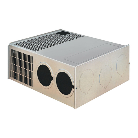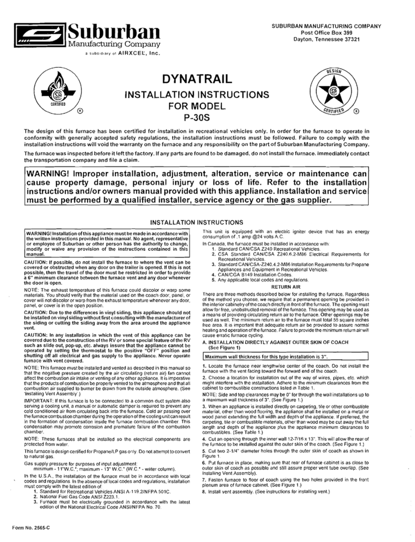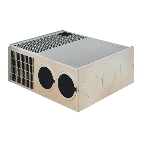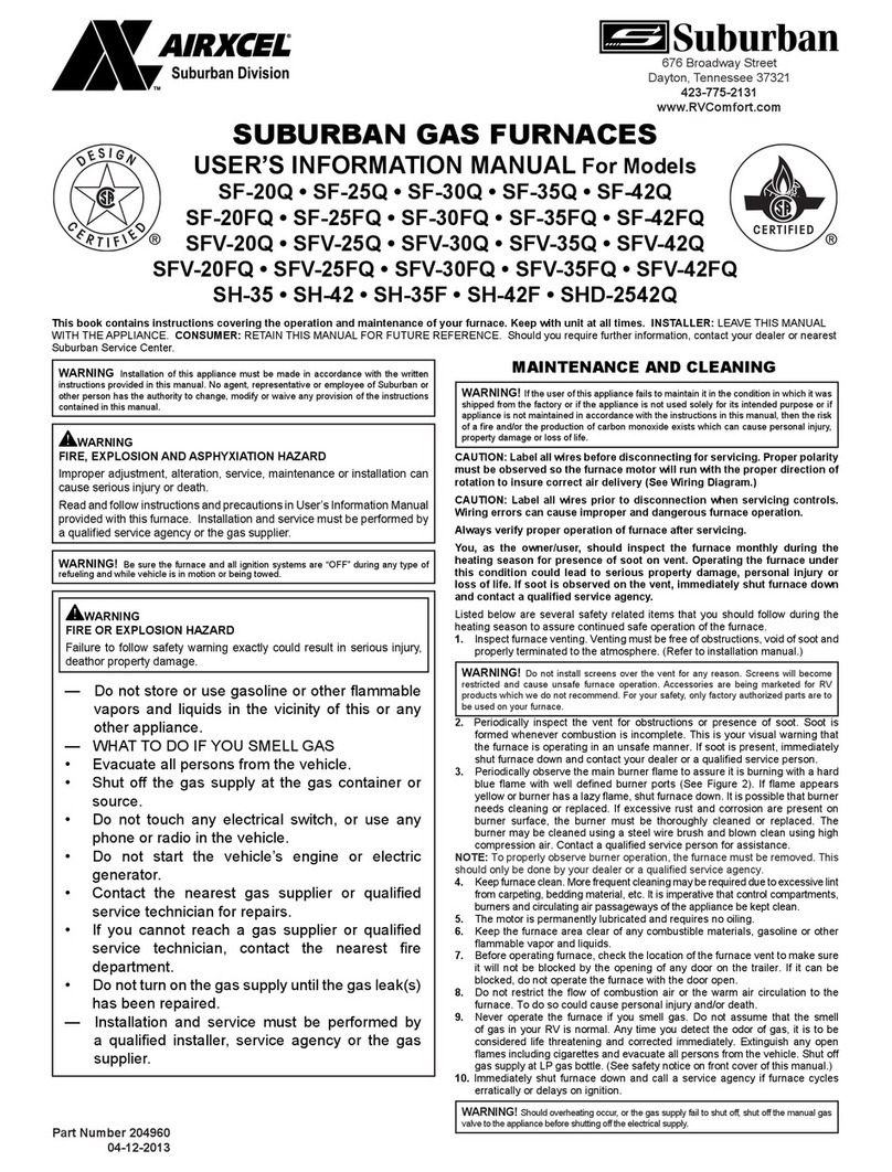
The furnace cabinet must extend through the coach cabinetry 1318" as shown
in Figure 1. The 1 318" extension must be held in order to assure that the front
grille will properly attach to the furnace cabinet. Adequate clearances must be
maintained around furnace cabinet so that the unit will be accessible for
servicing.
TO INSTALLTHE FURNACE
1. Locate the furnace near lengthwise center of the coach. Do not install the
furnace with the vent facing toward the forward end of the coach.
2. Select a location for installation out of the way of wires, pipes, etc. that might
interfere with installation. Adhere to the following minimum clearances from the
furnace cabinet to combustible construction.
Back
-
0" Top
-
518"
Floor
-
0" Sides
-
518"
NOTE:Sideandtop clearances of furnace cabinetmaybe
0"
forthroughthewall
installations up to a maximum of 2 112" wall thickness (See Figure 2.)
The following minimum clearances from the warm air discharge grille to
combustible materials must be maintained:
ModelsNT-12SE, NT-16SE, NT-POSE
Front
-
24 Top
-
1" Floor
-
114"
Left Side
-
1" Right Side
-
8" or Left Side
-
8"
Right Side
-
1"
(See Figure 8)
I
Models NT-12SE and NT-16SE only
I
Front
-
12" Top
-
1" Floor
-
114"
Side 0"'
'NOTE: Must provide an additional 12 sq, in, of return air
when side clearance is
On
-
8
(See Figure 9)
3.
When anappliance is installeddirectlyoncarpeting, tile,orother combustible
material other than wood flooring, the appliance shall be installed on a metalor
wood panel extending the full width and depth of the appliance. If preferred,the
carpeting, tile or combustible materials, otherthan wood maybecutawaythefull
length and depth of the appliance plus the appliance minimum clearances to
combustibles.
4.
Cut or frame an opening in the coach cabinetry 109/16x 103/16as shown
in Figure 2 or Figure 3.
5.
Slide the front of the furnace through the opening and extend it beyond the
coach cabinetry 1 318" as shown in Figure
2
or Figure 3.
6. Determine
"X"
dimension as shown in Figure 1.
7.
Determine "Y"dimension as shown in Figure 1.
8.
If
X
-
Y
is less than 21", then an opening
9
518" x 9
318"
must be cut through
the inner wall only. DO NOT CUT THROUGH COACH SKIN. (See Figure 2.)
Next, locate the center line of the exhaust and intake tube. Cut two 2 114"
diameter holes through the outer skin as shown in Figure 4.
NOTE: Whenever the furnace cabinet is installed through the outside wall, the
return air louvers on the furnace cabinet must not be blocked. The maximum
projection of the furnace cabinet into the wall is 2 112". (See Figure 2.)
NOTE:Furnacecabinet approved for
0"
clearanceto combustible materialsrear
2 112" of furnace cabinet.
9.
If
X
-
Y
is 21" or greater, two melhods may be used to install the furnace.
a. Cut a
4"
x
7
112" opening through combustible wall as shown in Figure
3.
DO NOT CUT THROUGH TRAILER SKIN. Next, locate the center line of the
exhaustand intake tube. Cuttwo 2 114" diameter holes throughlrailer skin. (See
Figure4.)
b.
If
you do not wish to cut the 4"
x
7
112opening, locate the center line of
the exhaust and intake tube as shown in Figure
4.
Next,cut two 2 314" diameter
holesthrough trailer skin and alsothecombustiblewall of thetrailerasillustrated
in Figure
6.
Care must betaken when locating the center lineof the exhaust and
intake tube as well as when cuttingthe holes in orderto assurea318" clearance
around the exhaust and intake tube to combustible materials.
10. Refer to the chart in Figure 1 and select the range for which the
'X'
dimension falls. The intake tube length directly to the left of the selected range
is the length required. NOTE: The
7
314" length exhaust tube assembly will
accommodate all approved installation depths
-
only the intake tube must be
ordered when needed. Under no circumstances should the standard
5"
intake
tube be cut or altered to adapt to the 21"
-
23 114range.
11. Secure furnace to the floor using the two holes provided in the front area of
the furnace cabinet. (See Figure 2 or Figure 3.)
12. NOTE: OPTIONAL DISCHARGE DUCT ADAPTER -The cabinet has a 4"
diameter knockout on the left side of cabinet. (See F~gure6A.) A
4"
diameter
connector can be attached to this location to providea warmair discharge duct.
(Notto exceed 10in length.)
CONNECTINGGAS SUPPLY
A 318" flare connection is provided on the right side of the furnace for the gas
supply connection to the furnace.
NOTE: Be sure all male joints have been treated with a sealing compound
resistant to the action of liquefied petroleum (LP)gas.
In order to maintain a check on gas supply pressure to the furnace. Suburban
advises the installer to provide a 118" NPT plug tap for test gauge connection
immediately upstream of the gas supply connection to the furnace.
NOTE:The appliance must bedisconnected from the gas supply piping system
during any pressure testing of that system at test pressure in excess of 112
PSIG.
The appliance must be isolated from the gas supply piping during any pressure
testing of thegas supplypiping system at test pressure equal to or lessthan 112
PSIG.
WARNING! All joints must becheckedfor leaks. Do not useopen flame
to check for leaks! Usea soap and water solution.
CONNECTING ELECTRICAL SUPPLY
CAUTION: These furnaces aredesignedfor a negativeground 12volt D.C.
system only. Do not attempt to alter the furnace for a positive ground
systemor connect thefurnacedirectly to 115voltsA.C. Damagetofurnace
component parts will occur.
Be sure all wiring to the furnace is of heavy enough gauge to keep the voltage
drop through it to a minimum. No. 12gauge wire is recommended. If any of the
original wire that is supplied with the appliance must be replaced, it must be
replacedwith Type 105" Cor its equivalent.
Connect the power supply to the red and yellow wlres onthe right side of the
furnace. The wires are color coded, red for positive
(+)
and yellow for negative
(-).
This polarity must beobserved so the furnace motor will run with the proper
direction of rotation to insure correct air delivery. (Seewiring diagram.)
If the furnace power supply is to be from a convertor, we recommend that the
convertorsystem usedto power thefurnace bewired in parallel with the battery.
This will serve two purposes:
1. Providea constant voltage supply to the furnace.
2. Filter any A.C. spikes or volt surges.
NOTE: Furnace models NT-12SE, NT-l6SEAND NT-POSEare equipped with
an electric ignitor device that has an energy consumption of.1 amps at 12volts
D.C.
CONNECTING THERMOSTAT
Locatethe roomthermostat approximately4 112 feet above!he flooronaninside
bulkhead where it is not affected by heat from any source except room air.
Connect the thermostatwires to the blue wires on the right side of the furnace.
(See wiring diagram.)
INSTALLING VENT ASSEMBLY
The vent outlet must be installed so it is inthe same atmospheric pressure zone
as the combustion air intake. The exhaust and intake tubes must be ~nstalled
from the outside, pass through the RV skin and slide onto the furnace exhaust
and intake.
WARNING! Do not alter the vent assembly supplied with this furnace.
Any modificationswill result inimproperinstallationwhich couldcause
unsafe furnace operation.
CAUTION! Combustionair must not bedrawnfrom the living area. All air
for combustion must bedrawn from the outside atmosphere. All exhaust
gases must be vented to the outside atmosphere
-
never inside the RV.
Therefore, it isessential to insure that the vent cap and tube assemblies
are properly installed.
1. Apply caulking to RV skin behind vent cap as shown in Figure 6. Apply
caulking generously around perimeter of vent cap and across center as shown.
2. Insert intake tube through RV skin and slide it onto the furnace intake (See
Figure 1.) Minimum tube overlap of 112" is required.
3.
Insert vent cap exhaust tube through RV skin and slide it onto the furnace
exhaust (See Figure 1.) Minimum tube overlap of 1 114" is required.
4.
Attachvent cap assembly to outer skin of RV withthe six (6)screws provided.
Do not install vent assembly upsidedown. The words "Suburban" and "Dayton,
Tenn."must be riaht side UD.
--
-
-
Due to high temperatures, the unit should belocated out of traffic and
away from furniture and draperies.
Children and adults should be alerted to the hazards of high surface
temperatures andshould stay away to avoid burns or clothing ignition.
Youngchildrenshouldbecarefullysupervisedwhentheyareinthesame
roomasthe unit.
Clothing orotherflammablematerialshould not beplacedonornearthe
unit.
Any safety screen or guard removed for servicing the unit must be
replaced prior to operating the unit.
Theareaaroundthe unit mustbekeptclearfromcombustible materials,
gasolineand other flammable vapors and liquids.
Installation and repairs should bedone bya qualified service person.
The unit should be ins~ectedbefore use and at least annuallv bv a
qualified service person: Morefrequent cleaningmayberequireddueto
excessive lint from carpeting, beddingmaterial, etc. It isimperative that
control compartments, burners, and circulating air passageways of the
~ ~
I
unit
be
kept clean.
I


