TABLE OF CONTENTS
SPECIFICATIONS ..............................................................................................................................................................
TABLE OF CONTENTS ......................................................................................................................................................
SERVICING NOTICES ON CHECKING .............................................................................................................................
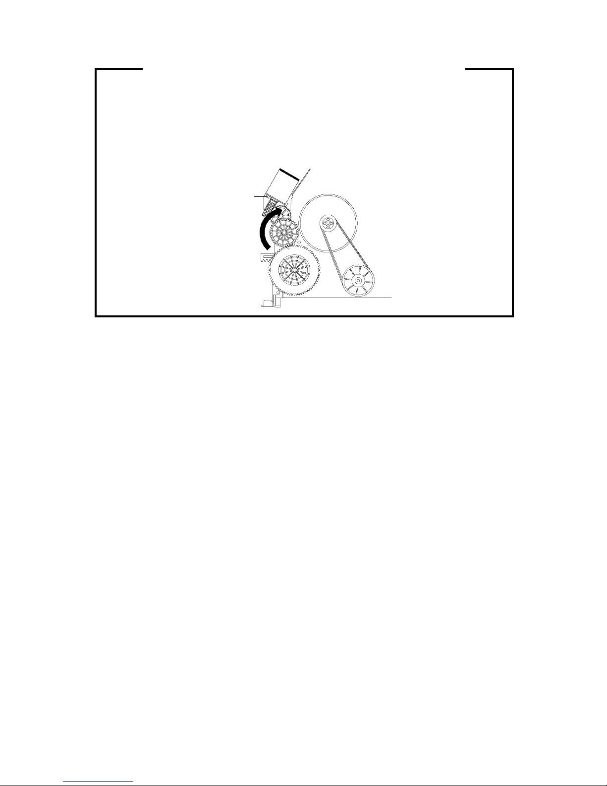
TAPE REMOVAL METHOD AT NO POWER SUPPLY......................................................................................................
DISASSEMBLY INSTRUCTIONS
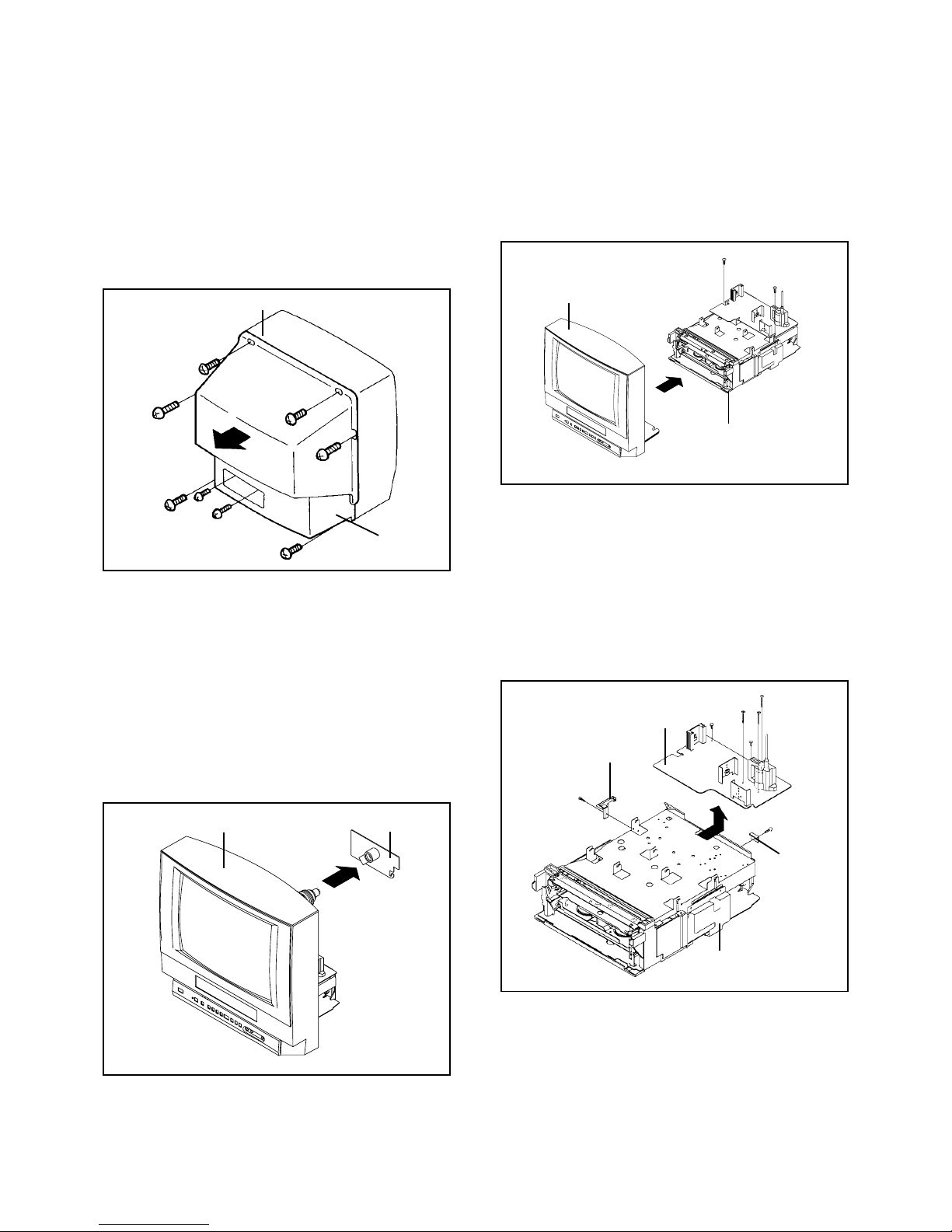
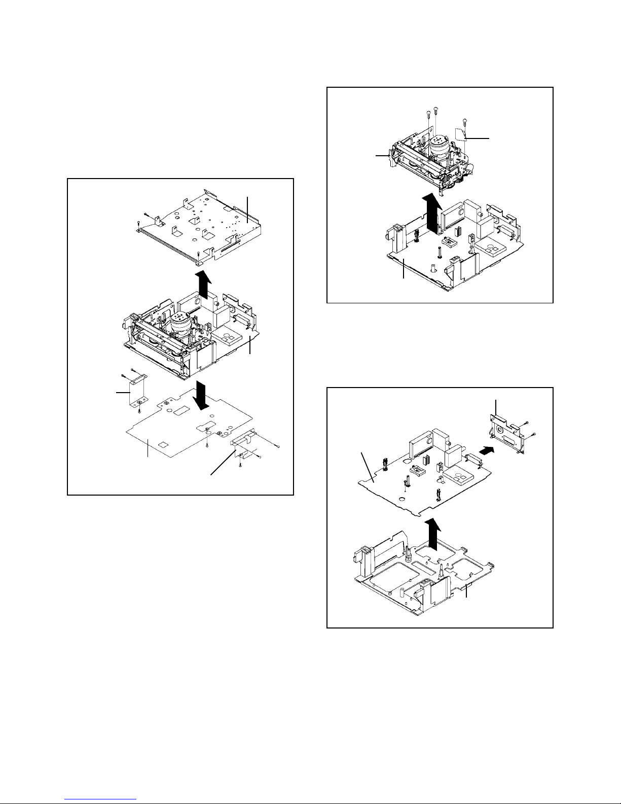
REMOVAL OF MECHANICAL PARTS AND P.W. Boards ..............................................................................................
REMOVAL OF DECK PARTS .........................................................................................................................................
REMOVAL OF ANODE CAP ...........................................................................................................................................
REMOVAL AND INSTALLATION OF FLAT PACKAGE IC .............................................................................................
KEY TO ABBREVIATIONS .................................................................................................................................................
SERVICE MODE LIST ........................................................................................................................................................
PREVENTIVE CHECKS AND SERVICE INTERVALS .......................................................................................................
WHEN REPLACING EEPROM (MEMORY) IC ..................................................................................................................
SERVICING FIXTURES AND TOOLS................................................................................................................................
PREPARATION FOR SERVICING .....................................................................................................................................
VCR TEST TAPE INTERCHANGEABILITY TABLE ...........................................................................................................
MECHANICAL ADJUSTMENTS
CONFIRMATION AND ADJUSTMENT ...........................................................................................................................
CONFIRMATION AND ADJUSTMENT OF TAPE RUNNING MECHANISM ..................................................................
MECHANISM ADJUSTMENT PARTS LOCATION GUIDE .............................................................................................
ELECTRICAL ADJUSTMENTS
ADJUSTMENT PROCEDURE.........................................................................................................................................
BASIC ADJUSTMENTS ..................................................................................................................................................
PURITY AND CONVERGENCE ADJUSTMENTS ..........................................................................................................
ELECTRICAL ADJUSTMENT PARTS LOCATION GUIDE .............................................................................................
TROUBLESHOOTING GUIDES .........................................................................................................................................
IC DESCRIPTIONS ............................................................................................................................................................
SERVO TIMING CHART ....................................................................................................................................................
SYSTEM SWITCH MODE ..................................................................................................................................................
SEMICONDUCTOR BASE CONNECTIONS......................................................................................................................
BLOCK DIAGRAMS
TV ....................................................................................................................................................................................
Y/C/AUDIO/HEAD AMP...................................................................................................................................................
MICON/POWER ..............................................................................................................................................................
IF/21PIN/IN/OUT .............................................................................................................................................................
T'TEXT.............................................................................................................................................................................
PRINTED WIRING BOARDS (SYSCON) ...........................................................................................................................
Y/C/AUDIO/HEAD AMP SCHEMATIC DIAGRAM ..............................................................................................................
MICON SCHEMATIC DIAGRAM ........................................................................................................................................
POWER SCHEMATIC DIAGRAM ......................................................................................................................................
21PIN/IN/OUT SCHEMATIC DIAGRAM .............................................................................................................................
CHROMA/IF SCHEMATIC DIAGRAM ................................................................................................................................
SOUND AMP SCHEMATIC DIAGRAM ..............................................................................................................................
SECAM CHROMA/HI-FI .....................................................................................................................................................
REGULATOR SCHEMATIC DIAGRAM.............................................................................................................................
T'TEXT SCHEMATIC DIAGRAM ........................................................................................................................................
PRINTED WIRING BOARDS (MAIN/CRT/POWER SW./IF) ..............................................................................................
TV POWER SCHEMATIC DIAGRAM .................................................................................................................................
DEFLECTION SCHEMATIC DIAGRAM .............................................................................................................................
CRT SCHEMATIC DIAGRAM.............................................................................................................................................
IF SCHEMATIC DIAGRAM ................................................................................................................................................
INTERCONNECTION DIAGRAM .......................................................................................................................................
WAVEFORMS ....................................................................................................................................................................
MECHANICAL EXPLODED VIEW......................................................................................................................................
MECHANICAL REPLACEMENT PARTS LIST ...................................................................................................................
ACCESSORY REPLACEMENT PARTS LIST ....................................................................................................................
CHASSIS EXPLODED VIEW (TOP VIEW) ........................................................................................................................
CHASSIS EXPLODED VIEW (BOTTOM VIEW) ................................................................................................................
CHASSIS REPLACEMENT PARTS LIST...........................................................................................................................
ELECTRICAL REPLACEMENT PARTS LIST ....................................................................................................................
A1-1
COVER
A1-1
A2-1
A2-2
B1-1, B1-2
B2-1~B2-6
B3-1
B4-1, B4-2
C1-1, C1-2
C2-1
C3-1, C3-2
C4-1
D1-1
D1-2
D1-3
D2-1, D2-2
D2-2, D2-3
D2-4
D3-1
D3-1~D3-4
D3-5
D3-6
E-1~E-27
F1-1~F1-3
F2-1
F2-2
G-1
H-1
H-2
H-3
H-4
H-5
I-1~I-3
I-4
I-5
I-6
I-7
I-8
I-9
I-10
I-11
I-12
I-13~I-15
I-16
I-17
I-18
I-19
I-20
J-1, J-2
K1-1, K1-2
K1-3
K1-3
K2-1
K2-2
K2-3
K3-1~K3-4