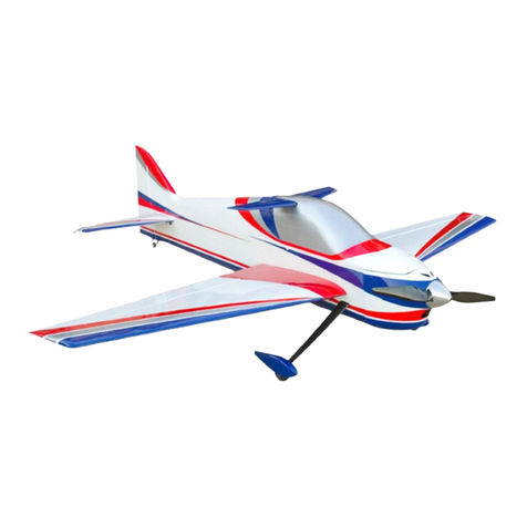
AJ Aircraft Laser 230z User manual

56” & 60” AJ Laser 230z
Assembly Instructions

aj-aircraft.com
Page 1
Congratulations
Whether you're looking to go out and go 3d huckin' or lay down a smooth-as-butter precision flight, the 56” or
60” Laser 230z is for you! The wings have been thoroughly refined to allow precision flying, while not
sacrificing any 3d characteristics. With a generous fuselage height, the model flies as well on its side as it does
upright. Generously sized control surfaces give you excellent authority at all speeds. The Laser 230z features
an awesomely light but strong airframe and a light wing loading that will handle anything you want it to.
Building the airplane is very straight forward. The rudder cables are pre-installed, hinges are pre-installed but
not glued, and pre-installed blind nuts in the wing tips for the included SFG's make it easy to get this bird in
the air in no time flat.
The 60" Laser 230z is the perfect "throw in your car for a few flights at the field" airplane. After flying this
baby just once, we think it will be your go-to plane and put a smile on your face every time you fly it!
Up Your Game! Fly AJ Aircraft
AJ Aircraft thanks you for the purchase of this airplane. Top
grade materials and precision assembly have been used to
make this a top quality aircraft. Following the directions
closely, will assure you many hours of thrilling flight. Two
years of design, development and testing has gone into this
airframe. We hope you’re as happy with it as we are!
WARNING!
AJ Aircraft’s extensive testing ensures a high quality kit that has gone through many stages to provide you with
a safe, reliable, airframe. Poor assembly will lead to an unsafe model and therefore the instructions must be
followed closely. Should you have any questions, please do not hesitate to contact us. The safe operation of
this model is your responsibility and yours alone. If you are a beginner or have never flown a model of this
size and power you should attempt it with the help of an experienced pilot. This product should not be
considered a toy, but rather a sophisticated, working model that functions much like a full-scale airplane.
Because of its performance capabilities, this product, if not assembled and operated correctly, could cause
injury to you or spectators and damage to property.
This aircraft should be flown in accordance to the AMA safety code. It is highly recommended that
you join the Academy of Model Aeronautics in order to be properly insured and to operate your model at
AMA sanctioned flying fields. If you are not willing to accept all liability for the use of this product please
return if to the place of purchase immediately.
AJ Aircraft does not accept responsibility or liability for damages resulting from use of this product.

aj-aircraft.com
Page 2
Contents
Congratulations.......................................................................................................................................................................1
Contents.................................................................................................................................................................................. 2
Features ..................................................................................................................................................................................3
56” Laser 230z.....................................................................................................................................................................3
60” Laser 230z.....................................................................................................................................................................3
Optional Configurations.......................................................................................................................................................... 3
Recommended Items for Completion.....................................................................................................................................4
56” Laser 230z.....................................................................................................................................................................4
60” Laser 230z.....................................................................................................................................................................4
Tools Needed ..........................................................................................................................................................................4
Covering ..................................................................................................................................................................................5
Wings ......................................................................................................................................................................................5
Landing Gear.........................................................................................................................................................................10
Fuselage ................................................................................................................................................................................12
Elevator.................................................................................................................................................................................14
Rudder...................................................................................................................................................................................18
Pull-Pull Rudder Control....................................................................................................................................................18
Push-Pull Rudder Control..................................................................................................................................................21
Electric Motor .......................................................................................................................................................................22
Cowl & Canopy......................................................................................................................................................................22
Radio Installation & Setup ....................................................................................................................................................24
These assembly instructions apply to the 56” and 60” Laser 230z.
Most of the photos in this manual are of the 60” Laser. However most of the assembly steps are the same.
Information specific to a size model will be indicated.
Before starting, read through the entire set of instructions to familiarize yourself with the
process.
If there’s ever a question, contact AJ Aircraft. 734-244-4015
Additional assembly information can be found in assembly videos on the
AJ-Aircraft YouTube Channel
Build Video #1 Build Video #2

aj-aircraft.com
Page 3
Features
56” Laser 230z
Specs:
•Wing Span - 56"
•Length - 54"
•AUW 4-4.5 lbs
•Electric Power 90amp ESC
4s 3300mah LiPo
•Radio - 5 Channel
•4 High Torque Micro Servos
What's in the box:
•56” Laser 230 Airframe
•Main Wings & Ailerons
•Foil Wing Bags
•Carbon Fiber Wing Tube
•Side Force Generators (SFGs)
•Horizontal Stabilizer & Elevator
•Rudder
•Pre-hinged Control Surfaces
•Fiberglass Cowl & Wheel Pants
•Carbon Fiber Main and Tail Landing Gear
•Light Weight Foam Wheels
•Complete Hardware Package
•G-10 Control Horns
•Genuine Ultracote Covering
60” Laser 230z
Specs:
•Wing Span - 60"
•Wing Area- 740 Sq. In.
•Length - 57"
•AUW 5-6 lbs
•Electric Power 1400-1600 watts
90amp ESC
(5s 3700-4400mah)/(6s 3000-4000mah)
•Radio - 5 Channel
•4 High Torque Mini Servos
What's in the box:
•60” Laser 230 Airframe
•Main Wings & Ailerons
•Foil Wing Bags
•Carbon Fiber Wing Tube
•Side Force Generators (SFGs)
•Horizontal Stabilizer & Elevator
•Rudder
•Pre-hinged Control Surfaces
•Fiberglass Cowl & Wheel Pants
•Carbon Fiber Main and Tail Landing Gear
•Light Weight Foam Wheels
•Complete Hardware Package
•Ball Links and Turnbuckles
•G-10 Control Horns
•Genuine Ultracote Covering
Optional Configurations
Only applies to the 60” Laser 230z.
You have the option of using a pull-pull rudder servo or a push-pull rudder servo setup. Fasteners, control horns and
servo connecting rods are provided for optional rudder setups.

aj-aircraft.com
Page 4
Recommended Items for Completion
56” Laser 230z
•Hacker A40-10S (750kv, 900Watts)
•Castle Talon 90 ESC
•Xoar 14x7 or 15x6 Prop
•Battery –4s 3300mah 25C Lipo
•(4) x Mini High Torque Digital Servos
Hitec 85MG, 5085 or 5087 servos
•(2) x 6” Servo Extensions for the Ailerons
•(1) x 18” Extension for the Elevator
•(3) x 1” Single Servo Arms for the Ailerons & Elevator
•(1) x 1.75” Double Servo Arm for the Pull-Pull Rudder
•2” (50mm) Spinner
•5 Channel Full Range Receiver
60” Laser 230z
•Hacker A50-14XS (520kv, 1100Watts)
•Castle Talon 90 ESC
•Xoar 15x8 or 16x8 Prop
•Battery - 5s 3700-4400mah or 6s 3000-4000mah
•(4) x Mini High Torque Digital Servos
Hitec 7245 or MKS 737
•(2) x 6” Servo Extensions for the Ailerons
•(1) x 12” Extension for the ESC
•(1) x 18-24” Extension for the Elevator
•(1) x 18-24” Extension for the Optional Push-Pull
Rudder
•(3) x 1.25” Single Servo Arms for the Ailerons &
Elevator
•(1) x 1.75” Double Servo Arm for the Pull-Pull Rudder
or (1) x 1.25” Single Arm for the Push-Pull Rudder
•2-1/4” (57mm) Spinner
•5 Channel Full Range Receiver
Tools Needed
Blue Painter’s Masking Tape
Thin CA Glue
30 Minute Epoxy
Denatured Alcohol
Paper Towels
Removable Thread Locker (Loctite 242, Blue)
Metric & Imperial Allen Wrenches
Hobby Knife & Fresh Blades
Covering Iron (Trim Iron)
Clamps
Small Flat File
Electric Drill w/ Assorted Small Bits (1/16”, 5/64”)
Small Flat Blade Screwdrivers
Small Phillips Screwdriver
Sandpaper (150-220 Grit)
Pliers
Measuring Tape & Ruler

aj-aircraft.com
Page 5
Covering
The covering on your Laser may have developed loose areas through temperature and humidity changes between
manufacturing and shipping. This may also occur during the summer heat. The covering may require retightening a few
times during your first summer of flying.
Take a few minutes to go over all of the seams making sure all edges are secure. Then proceed to shrinking any area
that may need tightening. (Use an iron on all seams. Use a heat gun on open areas and sheeted areas. An iron can be
used in open and sheeted areas but hold the iron slightly above the surface. You don’t want press the covering into the
wood. Using an iron sock will reduce scratches.
•Genuine Ultracote covering.
•Retro Scheme (True Red HANU866, White HANU870, Bright Yellow HANU872)
•Patriot Scheme (True Red HANU866, White HANU870, Midnight Blue HANU885, Bright Yellow HANU872)
Wings
Carefully locate the aileron
servo pocket. Shining a light
through opposite side of the
wing will help highlight the
pocket location. Use a new
hobby knife blade to cut though
the covering. Cut from the
corners of the pocket towards
the center of the pocket so the
covering can be folded in.
Gently snap off the servo wire installation string (if it’s
attached) and temporarily secure it out of the way. Do
not pull it out of the wing!
Use an iron to seal around the servo pocket. Fold the cut
covering under the wing sheeting and attach it to the
inside edge of the pocket.
At 200-220°F (93-104°C) the adhesive on UltraCote® becomes active
allowing the covering to be attached to the model. While 220° will fully
bond the covering to the model it is well below the temperature that
causes UltraCote® to shrink.
At 300°F (149°C) the initial shrinking of UltraCote® begins.
At 350°F (176°C) UltraCote® reaches its maximum shrinking point.
Raising the temperature above this point will not cause further shrinkage.
Use as little heat as needed. Using too much heat may cause reshrinking
issues later.
Pro Tip - If the iron you're using does not display the actual temperature,
here is a tip that will ensure your iron is properly set.Water boils at
212°F. Allow your iron to warm up at a medium setting. When the iron
reaches its stabilized temperature, carefully pour a few drops of water on
the iron's surface. Adjust the temperature until the water just begins to
boil off. This method is surprisingly accurate and is generally within 10°
(of the exact application temperature of 220).

aj-aircraft.com
Page 6
Carefully locate the aileron control horn slots. Use a
covering iron to bond the covering in the area the control
horn will sit. Trim the covering away to expose the slots.
Be sure not to cut through to the top side covering.
The hinges should already be glued into the ailerons.
Give each of them a little pull to ensure they are securely
attached. It’s better to find a loose hinge now rather
than during a flight.
The wings are already slotted for the hinges. Use a
covering iron to secure the covering along the edge of the
wings and ailerons. Look at the wing hinge slots closely.
Make sure the covering will not interfere when gluing the
hinges. Cut away any covering that covers the hinge slot.
Slip each of the aileron hinges into the wing. Align the
end of the aileron to the wing tip.
Push the aileron tight against the wing closing the gap
between the two of them. Move the aileron to its
maximum desired deflection. Notice how the hinges pull
out slightly. If you close the hinge gap tightly you may
have trouble reaching maximum deflection of the aileron.
Experiment with the hinge position finding the best fit
before gluing.
Apply a piece of tape next to each hinge. This will help
you locate the hinges when you begin gluing them.
Check the aileron position at the hinges and wing tip
again before gluing.
Start with the hinge near the wing tip. Flex the aileron
slightly and apply a few drops of thin CA glue to one side.
Flex the aileron to its maximum position and return to
center. Then glue the opposite side.

aj-aircraft.com
Page 7
Close the gap between the aileron and wing to the
desired position at the fuselage end of the wing half. Flex
the aileron slightly and apply a few drops of thin CA glue
to both sides of the hinge. Again move the aileron back
and forth to its maximum positions. Once the end hinges
are securely positioned you can apply a few drops of thin
CA to both sides of the remaining hinges.
Use the control horns from the “Wings” part bag.
Use sand paper to roughen the lower portion of the
control horns on both sides. This will help the epoxy
bond to the control horn parts.
Test fit the control horn in the slot. Trim or file the slot as
needed to achieve a snug fit.
The control horn should go in all the way in until the
shoulder contacts the aileron. The linkage hole in the
control horn should be aligned with the hinge centerline.
With the control horn in position apply masking tape
around it. This will help keep excess epoxy off the
covering.
Apply epoxy to the slot in the aileron. Use a pin to help
push the epoxy in.

aj-aircraft.com
Page 8
Apply epoxy to the control horn and insert it into the slot.
Wipe away excess epoxy using a paper towel and
denatured alcohol.
Check the alignment along the hinge line as you did when
you test fit the control horn. Reposition as needed.
Allow the epoxy to partially cure. Peel away the masking
tape after the epoxy is securely holding the control horn
in place and still soft enough to easily remove the tape.
Set the wing aside and let the epoxy fully cure.
Connect the servo to a receiver and power supply. Turn
on your transmitter. Set trim and sub trim to zero. Install
a servo arm on the servo about perpendicular to the
servo’s side. Use the transmitter’s sub trim to make it
exactly perpendicular to the side of the servo.
Attach a servo extension and a safety clip to the servo.
Attach the servo wire to the installation string and gently
pull the wire through the wing as you insert the servo
into the wing.
Insert the servo into the pocket with the drive spline
towards the front of the wing. Pre-drill for the servo
mounting screws using a 1/16” drill. Remove the servo
and apply a drop of thin CA glue into each mounting
screw hole. This will harden the wood around the screws
and provide a more secure installation. Allow the CA glue
to dry before reinstalling the servo.

aj-aircraft.com
Page 9
Assemble a ball link to each end of a connecting rod.
(60” Laser - The connecting rods have a right hand thread
on one end and a left handed thread on the other.)
Use a socket head screw, a flat washer and a nylon lock
nut to connect a ball link to the aileron control horn.
(The brass ball in the link is offset. The larger reveal side
should be against the control horn and servo arm shown
below.)
Check the length of the assembly to the servo arm with
the aileron level with the wing. When the correct length
of the assembly is found, connect the ball link to the
servo arm. (Always adjust the connecting rod length with
the servo powered up and centered.)
Carefully locate and trim the covering over the 2
mounting holes in each of the side force generators and
the spacer plate.
The wing tips have a blind nut installed beneath the
covering. Use a hobby knife to trim away the covering.
(Use the holes in a spacer plate to help locate the holes in
the wing tip.) Assemble the spacer plate and the side
force generator to the wing with the supplied screws and
washers.

aj-aircraft.com
Page 10
Landing Gear
Landing gear parts bag contents are shown below.
The landing gear screws are supplied installed in the
fuselage. Remove these screws.
Install the carbon fiber landing gear using 2 washers from
the parts bag and the socket head screws. Apply thread
locker as you install these screws.
Fit the filler block to the bottom of the landing gear. You
may need to sand a cove down the center of the block to
fit without rocking.
The filler block can be held in position with strips of
covering material, packing tape, or it can be glued in
place.
(If you use packing tape you may need to trim the width.
Roll the tape out with the sticky side up. Lay a straight
edge down on the tape and cut with a new blade.)
File a flat on the wheel axels perpendicular to the axel
wrench flats.
Install a wheel on the axel with a wheel collar. Position
the collar set screw over the flat you filed.

aj-aircraft.com
Page 11
(You may prefer to install the wheels and wheel pants
later as a final assembly step. They may get in the way
when handling the fuselage during other assembly steps.)
Insert the wheel and axel into the wheel pant, then into
landing gear. Align the wheel pant indentation with the
landing gear. Add a nylon lock nut and tighten.
Predrill a 5/64” hole into the wheel pant.
Install 2 wood screws into each landing gear and wheel
pant.
Install the tail wheel after the rudder installation.
Install the tailwheel using 3 wood screws. Position the
joint of the tail wheel assembly directly over the rudder
hinge line and mark the position of the screws. Use the
longer screw in the rudder tiller arm. Turn the screws into
the fuselage and rudder. Remove the screws, add a drop
of thin CA glue to each hole to strengthen the wood, and
reinstall the screws. (Do not fully tighten the tiller arm
screw. The slot in the tiller arm allows the screw move
accounting for any misalignment between the assembly
& rudder.)

aj-aircraft.com
Page 12
Fuselage
Inspect the fuselage for any interior joints that may have
loosened as a result of shipping & handling. Apply thin
CA glue around the joints of the fuselage core, firewall,
fuselage formers, and rudder servo tray to strengthen.
Carefully locate the mounting holes for the wing and trim
away the covering. There will be 2 holes for wing
alignment pins, 1 hole for the wing bolt, 1 slot for the
servo lead, and 1 large hole for the wing tube.
Carefully locate the horizontal stabilizer pocket. Use an
iron to seal the covering around the edges of the pocket
before trimming. Use a new hobby knife blade to cut
though the covering.
60” Laser - Review the servo configurations as described
on page 3 before cutting the covering over the servo
pockets. There are 2 servo pockets below the horizontal
stabilizer slot on both sides of the fuselage on the 60”
Laser. (These are highlighted with tape). The front pocket
will be used for the elevator servo. The pocket near the
tail of the fuselage on the opposite side will be for a
rudder servo if you decide to use the push-pull
configuration.

aj-aircraft.com
Page 13
56”Laser - The elevator servo pocket is located in front of
the horizontal stabilizer slot on the 56” Laser. (There is
no rudder push pull servo pocket as in the 60” Laser.)
Use an iron to seal the covering around the edges of the
pocket before cutting. Cut the covering then fold it into
the pocket and attach it with an iron. Insert a servo into
the packet and pre-drill for the servo mounting screws.
60” Laser - If you choose to use a push-pull rudder servo
cut open the back pocket on the opposite side.
Slide the horizontal stabilizer through the fuselage
pushing it all the way forward. Center it side to side using
a ruler or tape measure.
Install and center the main wing tube. Look at the plane
from the back forward to make sure that the horizontal
stabilizer is parallel with the wing tube. Notice that the
horizontal stabilizer is tapered which may obscure the
actual alignment. If the stabilizer is not aligned use shims
or sand inside the pocket until it’s parallel.
Position the stabilizer perpendicular to the fuselage and
parallel to the main wing tube. Measure the distance
between the canopy latch and the corners of the
horizontal stabilizer. Adjust the stabilizer until the
measurements on both sides are equal. Continue
checking the stabilizer to ensure it is still centered side to
side as described above. Extra time spent here will go a
long way to improve the flight characteristics of your
airplane.

aj-aircraft.com
Page 14
Once the horizontal stabilizer is positioned glue it in place
with thin CA glue. Wick glue in on left and right sides, top
and bottom. The use of an applicator tip is suggested to
control the flow of thin CA glue and get it exactly where
you want it.
Elevator
The elevator hinges should already be glued in. Give each
of them a little pull to ensure they are securely attached.
The jointer plate between the elevator halves is also
already glued into one half of the elevator.
Install a control horn in the elevator using the same
procedure used when assembling the ailerons. If you cut
open the servo pocket in the right of the fuselage make
sure you are working with the right elevator half.
•Use a covering iron to bond the covering in the area
the control horn will sit.
•Trim the covering away to expose the slot.
•Sand the lower portion of the control horn.
•Test fit the control horn. The shoulder contacts the
elevator and the linkage hole should be aligned with
the hinge centerline.
•Mask around slot.
•Glue with 30 minute epoxy.
•Check the alighment again.
•Let cure.
•Remove masing tape.
Roughen up the jointer plate for the elevator halves with
sand paper so the epoxy will adhere better.
Test fit the elevator joiner plate to the opposite elevator
half. Ensure the elevator halves are not twisted. Adjust
the slot in the elevator as needed.

aj-aircraft.com
Page 15
The horizontal stabilizer is already slotted for the hinges.
Use a covering iron to secure the covering along the edge
of the stabilizer and the elevator. Look at the stabilizer
hinge slots closely. Make sure the covering will not
interfere when gluing the hinges. Cut away any covering
that covers the hinge slots.
Apply a piece of tape next to each hinge. This will help
you locate the hinges when you begin gluing them.
Start with the right elevator only.
Align the end of the elevator to the end of the stabilizer.
Close the gap at elevator counter balance to a minimum
clearance. Push the elevator tight against the stabilizer
closing the hinge gap. Move the elevator to its maximum
desired deflection. Experiment with the hinge position
finding the best fit with a minimum gap and best travel
before gluing.
Flex the elevator slightly and apply a few drops of thin CA
glue to each hinge. Flex the aileron to its maximum
position and back to center. Then glue the opposite side.
Apply masking tape around the jointer slot in the left
elevator half and to the horizontal stabilizer under the
jointer plate.
Test fit the left elevator to the stabilizer and jointer plate.
Align the end of the elevator to the end of the stabilizer.
Close the gap at elevator counter balance to a minimum
clearance. Push the elevator tight against the stabilizer
closing the gap. Move the elevator to its maximum
desired deflection. Make sure you get full travel before
gluing. Remove the left elevator when you are happy
with the fit.
Prepare 30 minute epoxy and apply it to the elevator slot
and the jointer plate.

aj-aircraft.com
Page 16
Install the left elevator and position it as you did during
the test fit. Wipe away excess epoxy that is pushed out.
Check the hinge line and counter balance gap as you
position the elevator. When you have the elevator
positioned where you want it apply a few drops of thin
CA glue to the hinges.
Wipe up the excess epoxy after the hinges are securely
glued. Remove all masking tape right away and clean
with paper towels and alcohol.
Tape the elevator in position algined to the stabilizer at
each counter balance.
Clamp the elevator halves together to allow the epoxy to
cure.
Connect the servo to a receiver and power supply. Turn
on your transmitter. Set trim and sub trim to zero. Install
a servo arm on the servo about perpendicular to the
servo’s side. Use the transmitter’s sub trim to make it
exactly perpendicular to the side of the servo.
Attach a servo extension onto the elevator servo lead and
use a safety clip to secure the connection.

aj-aircraft.com
Page 17
Insert a servo into the elevator servo pocket with the
drive spline towards the tail of the fuselage. Pre-drill for
the servo mounting screws using a 1/16” drill. Remove
the servo and apply a drop of thin CA glue into each
mounting screw hole. This will harden the wood around
the screws and provide a more secure installation. Allow
the CA glue to dry before reinstalling the servo.
Assemble a ball link to each end of a connecting rod. Use
a socket head screw, a flat washer and a nylon lock nut to
connect a ball link to the elevator control horn.
Check the length of the assembly to the servo arm with
the elevator level with the stabilizer. When the correct
length of the assembly is found, connect the ball link to
the servo arm. (Always adjust the connecting rod length
with the servo powered up and centered.)
56”Laser -
60” Laser -

aj-aircraft.com
Page 18
Rudder
60”Laser –The rudder control can be configured as a
push-pull system or as a pull-pull cable system. See the
configuration options listed on page 3.
Pull-Pull Rudder Control
The rudder is built with control horn slots for the push-
pull control system and the pull-pull control system for
the 60” Laser.The 56” Laser rudder is built with one
control horn slot for the pull-pull control system.
The blue masking tape indicates the control horn
locations. The pull-pull control horn slot is located higher
up on the rudder. Cut the rudder covering to expose the
control horn slots on both sides of the rudder.
Use sand paper to roughen up the center of the control
horn so the epoxy will adhere better. File a radius on the
corners so the control horn can be rotated through the
rudder slot.
Tests fit the control horn to the slot. Use a file to modify
the slot as needed. Center it side to side and align the
holes with the hinge line. The control horn should be
symmetrical about the hinge line.
Apply masking tape around the control horn slot on both
sides of the rudder.
Use 30 minute epoxy to glue the control horns in place.
Check the alignment, peal the masking tape away, and
clean up with alcohol.

aj-aircraft.com
Page 19
Check the alignment again and set aside for the epoxy to
cure. (Position the rudder and control horn so gravity
does not reposition the control horn for you.)
The hinges should already be glued into the rudder. Give
each of them a little pull to ensure they are securely
attached. The vertical stabilizer is already slotted for the
hinges. Use a covering iron to secure the covering along
the edge of the rudder and stabilizer. Look at the hinge
slots closely to make sure the covering will not interfere
when gluing the hinges. Cut away any covering that
covers the hinge slot.
Apply a piece of tape next to each hinge. This will help
you locate the hinges when you begin gluing them.
Slip each rudder hinges into a slot. Check the gap at the
top of the vertical stabilizer and the rudder counter
balance. Push the rudder tight against the stabilizer
closing the gap between the two of them. Move the
rudder to its maximum desired deflection. Notice how
the hinges may pull out slightly. Experiment with the
hinge position finding the best fit before gluing.
Start with the top hinge. Flex the rudder slightly and
apply a few drops of thin CA glue to one side. Flex the
rudder to its maximum desired position. Then glue the
opposite side.
Close the gap to the desired position. Flex the rudder
slightly and apply a few drops of thin CA glue the bottom
hinge. Again move the rudder back and forth to check its
position. Once the end hinges are securely positioned
you can apply a few drops of thin CA glue to both sides of
the center hinge.
Connect the servo to a receiver and power supply. Turn
on your transmitter. Set trim and sub trim to zero. Install
a servo arm on the servo about perpendicular to the
servo’s side. Use the transmitter’s sub trim to make it
exactly perpendicular to the side of the servo.
Other manuals for Laser 230z
5
Table of contents
Other AJ Aircraft Toy manuals

AJ Aircraft
AJ Aircraft Laser 230z User manual

AJ Aircraft
AJ Aircraft Acuity User manual

AJ Aircraft
AJ Aircraft Laser 230z User manual

AJ Aircraft
AJ Aircraft Raven 73" User manual

AJ Aircraft
AJ Aircraft 10th Anniversary 51" Slick 540 User manual

AJ Aircraft
AJ Aircraft Laser 230z User manual

AJ Aircraft
AJ Aircraft Laser 230z User manual

AJ Aircraft
AJ Aircraft 93 AJ Laser 230z User manual

AJ Aircraft
AJ Aircraft ARS 300 MkII User manual

AJ Aircraft
AJ Aircraft 2M AJ Acuity User manual