LGB Ge 4/4 II User manual

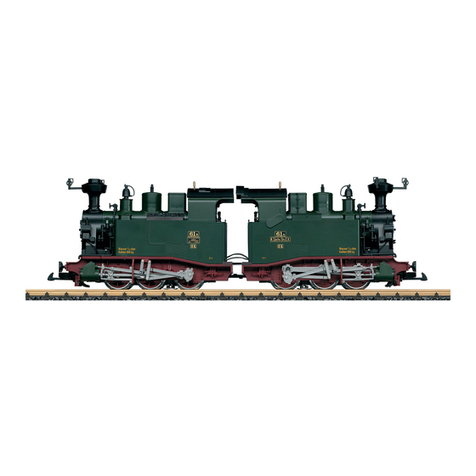
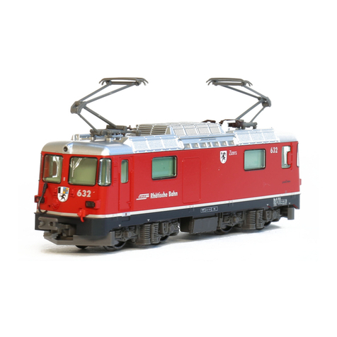
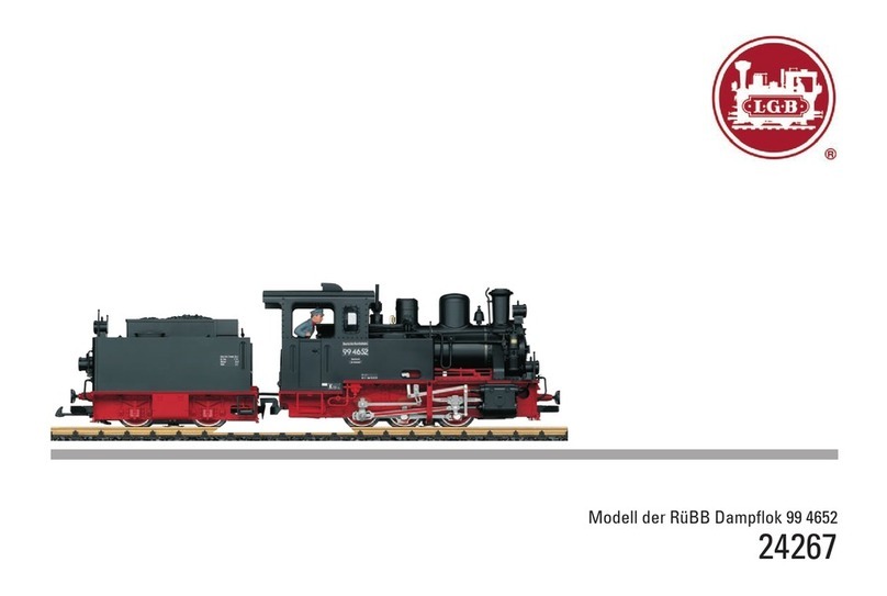
Modell der Ge 4/4 II
28434

2
DAS VORBILD
Als Ersatz für ältere elektrische Lokomotiven der Serien
Ge 2/4, Ge 4/6 und Ge 6/6 I bestellte die RhB 1970 zehn
vierachsige Hochleistungs-Thyristorlokomotiven mit Pha-
senanschnittsteuerung vom Typ Ge 4/4 II. Die Lokomotiven
mit den Nummern 611 - 620 wurden 1973 ausgeliefert. Mit
ihrer zukunftsweisenden Elektronik bewährten sich diese
Lokomotiven von Anfang an hervorragend. 1984/85 wurden
weitere 13 baugleiche Lokomotiven in Dienst gestellt.
Diese erste echte Allround E-Lok der Rhb übernahm
innerhalb kürzester Zeit den Schnellzugverkehr auf der
anspruchsvollen Albula-Linie Chur-St. Moritz. Bis heute hat
sich die Ge 4/4 II in allen Zuggattungen vom Güterverkehr
bis zum Schnellzugdienst bewährt. Seit Umstellung der
Arosa-Strecke auf die Stromart des RhB-Stammnetzes
werden alle Züge zwischen Chur und Arosa mit Ge 4/4 II
bespannt, so auch der Arosa-Express, den diese Lokomoti-
ven täglich durch das Engadin ziehen.
In den letzten Jahren hat die RhB bei einigen Lokomotiven
die ürsprünglichen runden unteren Stirnlampen durch
eckige Standard-Lampen ersetzt.
THE PROTOTYPE
To replace older electric locomotives of the types Ge 2/4,
Ge 4/6 and Ge 6/6 I, the Rhätische Bahn (RhB) in 1970 orde-
red ten modern four-axle locomotives with thyristor controls.
The locos were delivered in 1973 and numbered 611-620.
With their cutting-edge electronics, the locomotives imme-
diately were a great success. In 1984/85, the RhB received
another 13 identical locomotives.
These first true multi-purpose electric locos of the RhB
quickly took over the express train duties on the difficult
Albula line from Chur to St. Moritz. Today, the Ge 4/4 II has
proven its worth hauling every type of train from express
passenger to local freight service. Since the Arosa line has
been converted to the same electric power as the main
RhB network, all trains between Chur and Arosa have been
hauled by Ge 4/4 II, including the Arosa Express on its daily
run through the bucolic landscape of the Engadin.
For a few years, the RhB has replaced the original round
lower lights with standard square ones.

3
LE PROTOTYPE
Pour remplacer les locomotives électriques de type ancien
Ge 2/4, Ge 4/6 et Ge 6/6 I, les Chemins de fer rhétiques (RhB)
commandèrent en 1970 dix locomotives modernes à quatre
essieux et commandes par thyristors. Ces locomotives
furent livrées en 1973 et numérotées 611-620. Grâce à leur
électronique avancée, ces machines connurent immédiate-
ment un franc succès. En 1984/85, le Chemin de fer reçut 13
locomotives identiques supplémentaires.
Ces premières locomotives électriques vraiment polyva-
lentes du RhB furent rapidement utilisées pour tirer les
trains rapides sur la ligne difficile d’Albula entre Coire et
St Moritz. Les Ge 4/4 II ont depuis démontré leur potentiel,
tirant toutes sortes de convois, des trains rapides de voya-
geurs aux dessertes locales de marchandises. Depuis que
la ligne d’Arosa a été électrifiée comme le reste du réseau
principal du RhB, tous les trains entre Coire et Arosa sont
tirés par des Ge 4/4 II, y compris le Arosa Express pour la li-
aison journalière serpentant parmi les paysages bucoliques
de l’Engadine.
Depuis quelques années, le RhB a remplacé les feux inféri-
eurs ronds originaux par des feux carrés standard.
Inhaltsverzeichnis: Seite
Sicherheitshinweise 4
Allgemeine Hinweise 4
Funktionen 4
Betriebshinweise 4
Wartung und Instandhaltung 5
CV 6
Bilder 16
Table of Contents: Page
Safety Notes 8
General Notes 8
Functions 8
Information about operation 8
Service and maintenance 9
CV 10
Figures 16
Sommaire : Page
Remarques importantes sur la sécurité 12
Informations générales 12
Fonctionnement 12
Remarques sur l’exploitation 12
Entretien et maintien 13
CV 14
Images 16

4
Sicherheitshinweise
• DasModelldarfnurmiteinemdafürbestimmtenBe-
triebssystem eingesetzt werden.
• NurSchaltnetzteileundTransformatorenverwenden,
die Ihrer örtlichen Netzspannung entsprechen.
• DasModelldarfnurauseinerLeistungsquelleversorgt
werden.
• BeachtenSieunbedingtdieSicherheitshinweiseinder
Bedienungsanleitung zu Ihrem Betriebssystem.
• NichtfürKinderunter15Jahren.
• ACHTUNG!FunktionsbedingtescharfeKantenundSpitzen.
Allgemeine Hinweise
• DieBedienungsanleitungistBestandteildesProduktes
und muss deshalb aufbewahrt sowie bei Weitergabe des
Produktes mitgegeben werden.
• FürReparaturenoderErsatzteilewendenSiesichbittean
Ihren LGB-Fachhändler.
• http://www.maerklin.com/en/imprint.html
Funktionen
• DasModellistfürdenBetriebaufLGB-Zweileiter-Gleich-
strom-Systemen mit herkömmlichen LGB-Gleichstrom-
Fahrpulten vorgesehen (DC, 0 - 24 V).
• WerkseitigeingebauterMZS-Decoder(Mehrzugsystem).
• ZumEinsatzmitdemLGB-MehrzugsystemistdasModell
auf Lokadresse 03 programmiert.
Hinweis:VerwendenSiefürdiesesModelleinFahrgerätmit
mehr als 1 A Fahrstrom.
Betriebsartenschalter
Das Modell hat zwei Betriebsartenschalter im Führerstand
mit dem Lokführer (Bild 1). Mit dem oberen Schalter stellen
Sie ein, ob das Modell den Fahrstrom aus den Gleisen oder
aus der Oberleitung bezieht (Bild 3).
StellungU: StromversorgungausdenGleisen
StellungO: Oberleitungsbetrieb
Mit dem unteren Schalter (Bild 1, 2) können Sie folgende
Funktionenwählen:
Pos. 0 Lok stromlos abgestellt
Pos. 1 Beleuchtung und Steuerung der Pantographen
sind eingeschaltet
Pos. 2 Lokmotoren, Beleuchtung und Steuerung der
Pantographen sind eingeschaltet
Pos. 3 Lokmotoren, Sound, Beleuchtung und Steue-
rung der Pantographen sind eingeschaltet
Stromversorgung aus der Oberleitung
Diese Lokomotive kann ihren Strom über die LGB-Oberlei-
tung erhalten (siehe Betriebsarten). Auf der Unterseite des
Modells ist ein roter Punkt. Das Modell so auf die Schienen
stellen, dass der rote Punkt zu der Schiene weist, die nicht
mit dem Oberleitungs-Trafo verbunden ist (Bild 3).
VORSICHT! Eine Oberleitung darf nur im Analogbetrieb
zur Stromversorgung verwendet werden. Im Digitalbetrieb
mit dem LGB-Mehrzugsystem muss das Fahrzeug aus den
Schienen mit Strom versorgt werden, da sonst gefährliche
Spannungen entstehen können.

5
Mehrzwecksteckdose
Das Modell hat an der Vorder- und Rückwand jeweils eine
Mehrzweck-Steckdose für Flachstecker (Bild 4). Wenn
Sie einen Wagen mit Innenbeleuchtung oder mit einem
Sound-Modul ausrüsten, so können Sie dies hier anschließen
und so mit Gleisspannung versorgen. Dazu die Abdeckung
von der Steckdose abziehen. Sollte die Abdeckung zu fest
sitzen, diese vorsichtig mit einem kleinen Schraubenzieher
heraushebeln (jedoch nicht das äußere rechteckige Gehäuse
herausziehen).
Mehrzugsystem
Das Modell ist bereits werkseitig mit Decoder on board für
das LGB-Mehrzugsystem ausgerüstet. Es kann unverän-
dert auf herkömmlichen analogen Anlagen oder mit dem
digitalen Mehrzugsystem eingesetzt werden.
Beim Betrieb mit dem Mehrzugsystem verfügt die Lok über
eineLastnachregelung:DieMotordrehzahlwirdkonstant
gehalten, auch wenn sich die Belastung der Lok ändert, z.
B.inKurvenoderaufSteigungen.DieLastnachregelung
funktioniert nicht bei Höchstgeschwindigkeit.
Programmieren des Decoders
Zahlreiche Funktionen des Decoders können individuell
programmiert werden. Dazu werden Funktionswerte in
Registern (Configuration Variables - CVs) programmiert. Sie
können die Funktionswerte auch mit dem Universal-Handy
55015 programmieren.
• ZumnormalenBetriebistesnichtnotwendig,die
Funktionswerte zu ändern.
• UmbeiFehlprogrammierungendenAuslieferungszustand
der wichtigsten Register des MZS-Decoders wieder
zu programmieren, Funktionswert 55 in Register CV 55
eingeben. Beim Programmieren mit 55015 den Program-
miermodus “P” wählen (in der Anzeige erscheint “P --”).
Dann aufeinander folgend 6, 5 und 5 eingeben und rechte
Pfeiltastedrücken.DieAnzeigezeigterneut“P--”:5,5
und 5 eingeben und nochmals rechte Pfeiltaste drücken.
WARTUNG
Schmierung
Die Achslager hin und wieder mit je einem Tropfen LGB-
Pflegeöl (50019) ölen.
Austauschen der Glühlampen
Scheinwerfer: Vorsichtig das Glas von der Laterne hebeln.
Mit einer Pinzette die eingesteckte Glühlampe aus der Fas-
sung ziehen. Neue Glühlampe einsetzen. Modell wieder
zusammenbauen.
Innenbeleuchtung: Glühlampe mit einer Pinzette aus der
Fassung ziehen. Neue Glühlampe einstecken.
Austauschen des Haftreifens
Mit einem kleinen flachen Schraubendreher den alten
Haftreifenentfernen:DenaltenHaftreifenausderRille(Nut)
im Treibrad hebeln. Vorsichtig den neuen Haftreifen über
das Rad schieben und in die Rille (Nut) des Rads einsetzen.
Überprüfen, dass der Haftreifen richtig sitzt.

6
Register Belegung Bereich ab Werk
CV 1 Adresse 00 – 22 3
CV 2 Anfahrspannung 0 – 255 2
CV 3 Anfahrverzögerung 1 – 255 15
CV 4 Bremsverzögerung 1 – 255 3
CV 5 maximale Fahrspannung 1 – 255 255
CV 5 nach Eingabe von CV 6 (beim Programmieren mit älteren 55015)
Funktionswert im zu programmierenden Register
CV 6 CV-Nr. des zu programmierenden Registers
CV 29
Bit 0 = Fahrtrichtung
Bit 1 = Anzahl der Fahrstufen (14/28)
Bit 2 = Betriebsart (digital / analog+digital
Bit 5 = kurze / lange Adresse
0/1
0/2
0/4
0/32
4
CV 54
Übernahme-Funktion und Lastnachregelung
0 = Übernahme-Funktion aus, Lastnachregelung aus
1 = Übernahme-Funktion ein, Lastnachregelung aus
2 = Übernahme-Funktion aus, Lastnachregelung ein
3 = Übernahme-Funktion ein, Lastnachregelung ein
Übernahme-Funktion ein: Beim Betrieb mit 55015 kann nach Anwählen der Lok
die Reglerstellung 2 Sekunden lang nachgeregelt werden, ohne dass die Lok
anhält.
0 – 3 2
CV 55 Reset 55

7
Register Belegung Bereich ab Werk
CV 60 Lastregelung:max.Nachregelstärke 1 – 255 2
CV 61 Lastregelung:Regelgeschwindigkeit 0 – 255 32
CV 62 Lastregelung:Begrenzungdermax.Nachregelung 0 – 255 255
Elektronischer Sound
Beim Betrieb mit dem Mehrzugsystem können Funktionen
der Lok ferngesteuert werden. Über die Beleuchtungs-
taste (“9” bei Handys) wird die Lokbeleuchtung ein- und
ausgeschaltet. Über die Funktionstasten werden folgende
Funktionenbetätigt:
1: Pfeife
2: Bremsgeräusch
3: Pantographensenken/heben
4: AnsageaufdemBahnsteig
5: AnsageimZug
6: Aggregateaus/einzumAbstellenderLok
7: Umschaltenzwischen:hintererPantographhoch/beide
Pantographen hoch
8: Geräuschelektronikaus/ein
Das Modell hat einen Lautstärke-Regler in Fahrtrichtung
links hinter dem ersten Drehgestell (Abb. 5).
Die Pfeife kann auch mit dem beiliegenden LGB-Sound-
Schaltmagneten (17050) ausgelöst werden. Der Schalt-
magnet lässt sich zwischen die Schwellen der meisten
LGB-Gleise klipsen. Der Magnet befindet sich seitlich
versetzt unter dem eingeprägten LGBLogo. Plazieren Sie
den Magneten mit dem Logo auf der rechten Seite des
Gleises, um die Pfeife auszulösen, wenn die Lok diese Stelle
überquert.
Pantographen
Dieses Modell ist mit elektronisch gesteuerten Panto-
graphen ausgestattet. Entsprechend der Fahrtrichtung wird
automatisch der jeweils hintere Pantograph hochgefahren
und der vordere gesenkt. Die Pantographen können in der
unteren Stellung fixiert werden, indem sie in die Halterungen
eingeschnappt werden.

8
Safety Notes
• Thismodelmayonlybeusedwiththeoperatingsystem
designed for it.
• Useonlyswitchedmodepowersupplyunitsandtransfor-
mers that are designed for your local power system.
• Thislocomotivemustneverbesuppliedwithpowerfrom
more than one power pack.
• Paycloseattentiontothesafetynotesintheinstructions
for your operating system.
• Notforchildrenundertheageof15.
• WARNING! Sharp edges and points required for operation.
General Notes
• Theoperatinginstructionsareacomponentpartofthe
product and must therefore be kept in a safe place as
well as included with the product, if the latter is given to
someone else.
• PleaseseeyourauthorizedLGBdealerforrepairsor
spare parts.
• http://www.maerklin.com/en/imprint.html
Functions
• ThismodelisdesignedforoperationonLGBtwo-railDC
systems with conventional LGB DC train controllers or
power packs (DC, 0 - 24 volts).
• Thismodelcomesfromthefactorywithabuilt-inmulti-
train system decoder (multi-train system).
• ForoperationwiththeMulti-TrainSystem,themodelis
programmed to loco address 03.
Note:Usealocomotivecontrollerwithmorethan1ampof
train current for this model.
Mode of Operation Switch
There are two power control switches located in the cab
with the engineer (Figure 1). Use the upper switch to select
track or catenary power (Figure 3).
PositionU: trackpower
PositionO: catenarypower
Usethelowerswitchtoselectamongthefollowingfunctions:
Pos. 0 Locomotive stored on the track without power
Pos. 1 Power to lights and pantograph control
Pos. 2 Power to motors, lights and pantograph control
Pos. 3 Power to motors, sound, lights and pantograph
control
Catenary Power Operation
This locomotive can be operated with a powered catenary
system (see Operating Modes). The bottom of this model is
marked with a red dot. Place the model on the track with
the red dot pointing to the rail that is not connected to the
catenary power supply (Figure 3).
CAUTION! This model may be powered with a catenary on
analog layouts only. For operation with the digital Multi-
Train System, the model must use track power. Otherwise,
dangerously high voltages may result.
Multi-Purpose Socket
This model has “flat“ multi-purpose sockets, with removable
covers, on the front and rear of the loco (Figure 4). If you
are equipping a car with interior lighting or with a sound
effects module, you can connect it to the socket and power
that circuit with track voltage. To remove the cover of the
socket, pull it straight out. If the cover is tight, gently use a

9
small straight screwdriver to pry it out (do not pull out the
rectangular outer housing).
Multi-Train System
The model is equipped with a factory-installed onboard de-
coder for the LGB Multi-Train System. It can be used without
modifications on analog or digital layouts.
When operating with the Multi-Train System, the loco
features a “Back-EMF” function. This keeps the motor
speed constant, even when the load of the loco changes, for
example, in curves or on grades. This feature does not work
at top speed.
Programming the Decoder
Numerous functions on the decoder can be programmed
individually. To do this, function values are programmed in
registers (Configuration Variables - CVs). You also can pro-
gram the function values with the 55015 Universal Remote
Controller.
• Fornormaloperation,itisnotnecessarytochangethe
function values.
• Ifprogrammingresultsinunsatisfactoryoperation,
you can reprogram the factory pre-set values of most
importantCVs:ProgramregisterCV55tofunctionvalue
55. To reprogram the factory pre-set function values with
the 55015, select programming mode “P” (displays shows
“P --”). Then input 6, 5, and 5 and press the right arrow
button.Thedisplayshows“P--”again:Input5,5,and5
and press the right arrow button again.
SERVICE
Lubrication
The axle bearings should be lubricated occasionally with a
small amount of LGB Maintenance Oil (50019).
Replacing the light bulbs
Lanterns: Carefully pry the lens away from the lantern. Using
tweezers, remove and replace the bulb. Reassemble.
Cab light: Using tweezers, remove and replace the bulb.
Replacing the traction tire
Use a small, straight-blade screwdriver to replace the
tractiontire:Prytheoldtractiontireoutofthewheelgroove.
Gently insert the new traction tire into the wheel groove.
Make sure that the traction tire is seated properly in the
wheel groove.

10
Register Assignment Range Default
CV 1 Address 00 – 22 3
CV 2 Starting voltage 0 – 255 2
CV 3 Acceleration delay 1 – 255 15
CV 4 Braking delay 1 – 255 3
CV 5 Max. voltage 1 – 255 255
CV 5 After entry of CV 6 (when programming with older 55015 units) function value in
the register to be programmed
CV 6 CV number of the register to be programmed
CV 29
Bit 0 = Direction of travel
Bit 1 = Number of speed levels (14/28)
Bit 2 = Mode of operation (digital / analog+digital)
Bit 5 = short / long address
0/1
0/2
0/4
0/32
4
CV 54
Hand-off function and “Back-EMF”
0 = hand-off function off, Back-EMF off
1 = hand-off function on, Back-EMF off
2 = hand-off function off, Back-EMF on
3 = hand-off function on, Back-EMF on
Hand-off function on: When operating with 55015, you can adjust direction and
speed for two seconds after selecting a moving loco without causing the loco
to stop.
0 - 3 2
CV 55 Reset 55

11
Register Assignment Range Default
CV 60 Back-EMF:Max.adjustmentfactor 1 – 255 2
CV 61 Back-EMF:Adjustmentfrequency 0 – 255 32
CV 62 Back-EMF:Maximumadjustment 0 – 255 255
Sound
When operating with the Multi-Train System, you can remo-
tely control the loco’s functions. Press the lighting button
(“9” with remotes) to turn the loco lights on or off. Press the
functionbuttonstocontrolthefollowingfunctions:
1: Whistle
2: Brakesound
3: Raise/lowerpantographs(withsound)
4: Traindepartureannouncement
5: Trainannouncement
6: Off/onforparkingtheloco
7: Changepantographsettings:rearpantographup/both
pantographs up
8: Soundoff/on
The volume control is located underneath the model on the
left behind the first power truck (Fig. 5).
The whistle also can be triggered by the LGB Sound Magnet
(17050) included with this model. The 17050 snaps between
the ties of most LGB track sections. The magnet in the 17050
is under the LGB logo. If the contact is installed with the
logo on the right side of the track (in the direction of travel),
it will trigger the whistle as the model passes.
Pantographs
The model is equipped with electronically controlled
pantographs. The rear pantograph raises, and the front pan-
tograph lowers automatically, depending on the direction of
travel. The pantographs can be fixed in the „down“ position
by snapping them into their holders.

12
Remarques importantes sur la sécurité
• Lalocomotivenepeutêtreutiliséequ‘aveclesystème
d‘exploitationindiqué.
• Utiliseruniquementdesconvertisseursettransforma-
teurs correspondant à la tension du secteur local.
• Lalocomotivenepeutêtrealimentéeencourantquepar
une seule source de courant.
• Veuillezimpérativementrespecterlesremarquessurla
sécurité décrites dans le mode d’emploi de votre système
d’exploitation.
• Neconvientpasauxenfantsdemoinsde15ans.
• ATTENTION! Pointes et bords coupants lors du fonction-
nement du produit.
Informations générales
• Lanoticed‘utilisationfaitpartieintégranteduproduit;
elledoitdoncêtreconservéeet,lecaséchéant,transmi-
se avec le produit.
• Pourtouteréparationouremplacementdepièces,
adressez-vous à votre détaillant-spécialiste LGB.
• http://www.maerklin.com/en/imprint.html
Fonctionnement
• Lemodèleestprévupourêtreexploitésurdessystèmes
deux rails c.c. LGB avec des pupitres de commandes LGB
classiques en courant continu (DC, 0 - 24 V).
• DécodeurSMTintégré(avecexploitationmultitrain).
• Pourutilisationaveclesystèmemultitrain,lemodèle
réduit est programmé à l’adresse de locomotive 03.
Conseil:Pourcemodèle,utilisezunrégulateurdemarche
avec courant moteur supérieur à 1 A.
Commutateur de mode d’exploitation
Deux sélecteurs d’alimentation sont placés près du
conducteur à l’intérieur de la cabine (Img. 1). Utiliser le
sélecteur supérieur pour sélectionner l’alimentation par la
voie ou l’alimentation par la ligne à suspension caténaire
(Img. 3).
PositionU:alimentationparlavoie
PositionO:alimentationparlaligneàsuspensioncaténaire
Utiliserlesélecteurinférieurpourlesfonctionssuivantes:
Pos.0 Locomotivehorstension,arrêtée
Pos. 1 Alimentation de l’éclairage et manoeuvre des
pantographes
Pos. 2 Alimentation des moteurs, de l’éclairage et
manoeuvre des pantographes
Pos. 3 Alimentation des moteurs, du système d’effets
sonores, de l’éclairage et manoeuvre des
pantographes
Alimentation par ligne à suspension caténaire
Cettelocomotivepeutêtrealimentéeparuneligneàsus-
pension caténaire (voir Modes opératoires). Un point rouge
se trouve à la partie inférieure du modèle réduit. Placer le
modèle réduit sur les rails avec le point rouge dirigé vers le
rail qui n’est pas raccordé à la ligne à suspension caténaire
(Img. 3).
ATTENTION !Cemodèlepeutêtrealimentéparuneligne
à suspension caténaire uniquement sur les réseaux ana-
logiques.Ildoitêtrealimentéparlavoiepourpouvoirêtre
utilisé avec le système multitrain numérique, sinon, il y a
risque de surtensions dangereuses.

13
Sélecteur de fonctions
Ce modèle est équipé de douilles à usages multiples «plates»
avec couvercle amovible situées à l’avant et à l’arrière de la
locomotive. (Img. 4). Lorsque vous équipez un wagon d’un éc-
lairage intérieur ou d’un module son, vous pouvez le raccor-
der ici et l’alimenter ainsi en tension de voie. Pour enlever le
couvercle de la douille, tirez simplement dessus. S’il ne sort
pas, utilisez un petit tournevis droit pour le plier légèrement
(ne sortez pas le logement extérieur rectangulaire).
Système multitrain
Ce modèle est équipé d’un décodeur embarqué de série
pourlesystèmemultitrainLGB.Ilpeutêtreutilisésans
modification sur les réseaux analogiques ou numériques.
La locomotive possède une fonction de force contre-élec-
tromotrice (FCEM) lorsqu’elle est utilisée avec le système
multitrain. Cette fonction permet de conserver constante la
vitessedumoteur,mêmelorsquelachargedelalocomotive
change, comme par exemple en virage ou sur une pente. Cet-
te caractéristique ne fonctionne pas à la vitesse maximale.
Programmation du décodeur
Denombreusesfonctionsdudécodeurpeuventêtre
programmées individuellement. A cet effet, les valeurs de
fonction sont programmées dans des registres (variables de
conguration-CVs).Cesvaleurspeuventêtredéniesavec
l’appareil portable Universal-Handy 55015.
• Ilestinutiledechangerlesvaleursdefonctionenutilisa-
tion normale.
• Silaprogrammationnedonnepasderésultatssatisfaisants,
vous pouvez reprogrammer les valeurs attribuées par l’usine
auxprincipauxCV:ProgrammerleregistreCV55àlavaleur
de fonction 55. Cette opération reprogramme l’adresse de
locomotive à la valeur attribuée par l’usine. Pour reprogram-
mer les valeurs de fonction attribuées par l’usine au moyen
de la télécommande universelle 55015 (l’afficheur indique
«P- -»), entrer 6, 5 et 5 et appuyer sur le bouton flèche à
droite.L’afcheurindiquedenouveau«P--»:entrer5,5et5
et appuyer de nouveau sur le bouton flèche à droite.
ENTRETIEN
Lubrification
Lesroulementsdesessieuxdoiventêtrelubriésdetempsà
autre avec une goutte d’huile de nettoyage LGB (50019).
Remplacement des ampoules
Lanternes : Sortir avec précaution la lentille de la lanterne.
À l’aide de pincettes, enlever et remplacer l’ampoule.
Remonter le tout.
Éclairage de la cabine : Enlever et remplacer l’ampoule en
utilisant des pincettes.
Remplacement du pneu de traction
Utiliser un petit tournevis à lame droite pour remplacer le
pneudetraction:Sortiravecprécautionlevieuxpneudela
gorge de la roue. Placer avec précaution le pneu neuf dans
la gorge de la roue. S’assurer que le pneu de traction est
bien assis dans la gorge de la roue.

14
Register Affectation Domaine Valeur
d’usine
CV 1 Adresse 00 – 22 3
CV 2 Tension au démarrage 0 – 255 2
CV 3 Temporisation d‘accélération 1 – 255 15
CV 4 Temporisation de freinage 1 – 255 3
CV 5 Tension maximale 1 – 255 255
CV 5 Après définition de CV 6 (pour programmation avec ancien 55015)
Valeur de fonction dans le registre à programmer
CV 6 N° de CV du registre à programmer
CV 29
Bit 0 = sens de marche
Bit 1 = nombre de crans de marche (14/28)
Bit 2 = mode d’exploitation (numérique / analogique+numérique)
Bit 5 = adresse courte / longue
0/1
0/2
0/4
0/32
4
CV 54
Fonctions Transfert de contrôle et «FCEM»
0 = Fonctions Transfert de contrôle hors service, FCEM hors service.
1 = Fonctions Transfert de contrôle en service, FCEM hors service.
2 = Fonctions Transfert de contrôle hors service, FCEM en service.
3 = Fonctions Transfert de contrôle en service, FCEM en service.
Fonction Transfert de contrôle en service : Lorsque vous utilisez la télécomman-
de universelle 55015, vous pouvez changer le sens de la marche et la vitesse
pendant deux secondes après sélection d’une locomotive en mouvement sans
arrêter la locomotive.
0 - 3 2

15
Register Affectation Domaine Valeur
d’usine
CV 55 Réinitialisation 55
CV 60 Régulationdelacharge:forcederéajustagemaximale 1 – 255 2
CV 61 Régulationdelacharge:vitesseduréajustage 0 – 255 32
CV 62 Régulationdelacharge:limitationduréajustagemaximal 0 – 255 255
Effets sonores
Lesfonctionsdelalocomotivepeuventêtretélécommandé-
es lorsque cette dernière est uitilisée avec le système
multitrain. Appuyer sur le bouton d’allumage («9» sur les
télécommandes) pour allumer et éteindre l’éclairage.
Appuyer sur les boutons de fonction pour commander les
fonctionssuivantes:
1. Coups de sifflet
2. Bruit du freinage
3. Relèvement/abaissement des pantographes
5. Annonce
6. Marche/arrêtcompresseuretsoufeurpourgarerla
locomotive
7. Changementdelapositiondespantographes:panto-
graphe arrière relevé/ les deux pantographes relevés
8. Marche/arrêtdusystèmed’effetssonores
La commande de réglage du volume sonore est située sous
le modèle réduit, à gauche en arrière du premier bogie
moteur (figure 5)
Lesifetpeutégalementêtredéclenchéparl’aimantcom-
mutateur de son LGB (17050) fourni avec ce modèle réduit.
L’accessoire 17050 se met en place entre les traverses de la
plupart des sections de voie LGB. L’aimant de l’accessoire
17050 se trouve sous le logo LGB. Si le contact est installé
avec le logo du côté droit de la voie (dans le sens de la mar-
che), il déclenchera le sifflet au passage du modèle réduit.
Pantographes
La locomotive est équipée d’un système électronique de
manoeuvre des pantographes. Le pantographe arrière se
relève et le pantographe avant s’abaisse automatiquement
suivant le sens de la marche. Les pantographes peuvent
êtremaintenusenposition«repliée»enlesrentrantdans
leur support.

16
Bild 1, Betriebsartenschalter
Fig. 1, Power control switch
Img. 1, Modes d‘exploitation
Bild 2, Betriebsartenschalter
Fig. 2, Power control switch
Img. 2, Modes d‘exploitation
0 1 2 3
O U
0 1 2 3
0 1 2 3
0 1 2 3
0 1 2 3

17
Bild 3, Schema der Stromversorgung
Fig. 3, Wiring diagram
Img. 3, Schéma de câblage
1
0
2
M
Trafo 1
Trafo 1

18
Bild 4, Mehrzwecksteckdose
Fig. 4, Multi-purpose socket
Img. 4, Sélecteur de fonctions
Bild 5, Lautstärkeregler
Fig. 5, Volume Control
Img. 5, Commande de réglage du volume sonore

19

20
1
2
3
4
7
7
7
7
74
2
3
437
37
37
37
15
4
4
4
6
6
5
5
8
8
8
36
36
36
36
7
7
7
8
9
9
18
17
17
17
11
9
10
12
10
40
16
36
13
14
Details der Darstellung
können von dem Modell
abweichen.
This manual suits for next models
1
Table of contents
Languages:
Other LGB Toy manuals
Popular Toy manuals by other brands

Horizon Hobby
Horizon Hobby E-FLITE EFL491009 instruction manual

C-bionic
C-bionic Scorpio Grip X Sting manual

marklin
marklin 29442 user manual

GRAUPNER
GRAUPNER Taucher O.Wulf 6 manual

Sparkfun Electronics
Sparkfun Electronics PiRetrocade Assembly guide

Playskool
Playskool Sit `n Spin 34891/34890 user manual

Thomas & Friends
Thomas & Friends DGK89 instructions

Hangar 9
Hangar 9 Model 12 Viking 120cc instruction manual

Century Helicopter Products
Century Helicopter Products Raven 30 V2 instruction manual

Pilot Communications
Pilot Communications 50CC Assembly manual

Faller
Faller Zur Sonne Burnt-Down Restaurant Assembly instructions

H-KING
H-KING A-1 SKY RAIDER instruction manual