AKA EXCALIBUR User manual

Excalibur
Operator’s Manual
Table of Contents
Introduction 2
Specifications 2
Power Source 3
Air Supply 3
Excalibur Notes 4
Firing the Excalibur 4
Velocity Adjustment 4
Cleaning and Maintenance 5
Troubleshooting 6
Custom Work 7
Accessories 7
Ball Detent 7
Electronics 8
Hammer 10
Lightning Bolt 10
Other Component Parts 10
Pneumatics Regulator 11
Pnematics Ram 13
Screws and O-Rings 13
Sidewinder Regulator 14
Solenoid Valves 16
Trigger Frame 16
Tornado Valve 17
Schematics
Warnings and Important Safety Guidelines
Warning! The Excalibur paintball marker is not a toy!
Careless or improper use, including failure to follow
instructions contained within this manual, may result in
injury or death.
Read Operator’s Manual before use and comply with all
safety instructions. Do not fire this, or any marker, at a
person when at a close range. Observe all local laws,
regulations, and ordnances when using this marker. Use
only at paintball fields where safety codes are strictly
enforced.
You must be at least 18 years of age to purchase this
marker. Users under the age of 18 must do so only
under adult supervision. Use only bottles approved for
Nitrogen, compressed air, or CO2. Make sure all bottles
are hydro-tested according to DOT regulations.
Use only .68 caliber paintballs in this marker. Do not
attempt to fire foreign objects from this marker. Use an
approved barrel blocking device when your marker is
not in use. Always disconnect air source and switch off
power source when not in use. Never shoot at velocities
in excess of 300 FPS. Never put your fingers or foreign
objects in the feed tube of the marker.
Never expose battery to open flame or heat source.
When connecting or disconnecting the battery, take care
not to short out the battery.
Always wear eye protection when adjusting, servicing,
or using your marker. When doing any work to your
maker, make sure the power and air source have been
disconnected. Be sure all paintballs have been
removed. Seek professional assistance if you unsure
of anything.

Introduction
This manual is a work in progress and will be continously
updated as needed. If you see an area that needs work,
contact us thru e-mail and let us know. If you have
sugestions or a different method of doing something
that pertains to the Excalibur and its components, write
us with your suggestions. We decided to place the
manual on disk for the simplicty of keeping it up to date
and to eliminate paper waste. The manual was written
in HTML so it will be compatible with well over 95% of
the computers people use in their day-to-day life. A
PDF version of this document is also included on this
disk for users who prefer to print out their own hard
copy of the manual.
The ground work for the very first ideas of the Excalibur
were laid down back in 1988 as I was working on my
apprenticeship in the family machine shop - Leads Metal
Products, Inc. Leads Metal Product’s other division,
Endeco Soldering and Desoldering, had just finished
developing an electronically-controlled power vacuum
desoldering station which used solenoids and 4-way
solenoid valves to actuate the mechanism. Endeco had
been manufacturing and selling soldering and
desoldering irons since the late fifties.
At the time of the development of the new power vacuum
desoldering station, I had developed several paintball
gun prototypes, several blow back guns, and one
pneumatic blow forward. I had an idea and added a 4-
way solenoid valve from the desoldering stations to one
of my paintball gun designs. It worked great, but the 4-
way solenoid valves at the time were far too big to make
a portable paintball gun. I continued to develop the idea
but later shelved it when I went off to college in 1990.
In October 1998, after hearing many complaints about
the electronic markers available at that time, AKALMP
decided to build a paintball gun that would hold up to
the punishment that any paintball gun endures. Most
electronic markers are based on an inexpensive blow-
back semi-auto open bolt marker which limits their
performance. The Excalibur’s(tm) (pat pend) design
makes it the most advanced integrated paintball marker
in the world. The electronics are state-of-the-art but have
been kept simple for durability and longevity. The
mechanical components of the Excalibur(tm)(pat pend)
have been designed to give many years of flawless
operation with very little maintenance. The whole marker
was designed around the “KISS” (Keep It Simple Stupid)
principal. The design is very simple and rugged but is,
at the same time, very advanced. The outside of the
Excalibur(tm)(pat pend) may not look fancy, but the
inside is what is adavnced. The Excalibur(tm)(pat pend)
is built more like a high performance tank. We leave the
decoration up to customers and airsmiths. In addition,
we wanted to provide a warranty that was simple, not
long and complicated.
With many years of design and manufacturing knowledge
outside of paintball to draw from, AKALMP, Inc. and
LEADS METAL PRODUCTS, Inc. bring the paintball
community the finest paintball products available.
AKALMP has the finest products with the highest
performance ratings which will not be compromised.
President AKALMP, Inc.
Aaron K. Alexander
Specifications
Model: Excalibur(tm)(pat pend)
Version:1300-B Caliber: .68
Action: Closed Bolt Electo-pneumatic Operation
Gas Source: Compressed air, Nitrogen or CO2
Power Supply: 9 Volt battery ROF (Cyclic Rate): 13
BPS(MAX)
Standard Barrel Length: 12.0" Javelin (Cocker Threads)
Length: 8.125 inches
Height: 8.4 inches (Top of feed tube to bottom of grip)
Width: 1.75 inches
Weight: 3. lbs (Without battery & barrel)
Operating Pressure: 140-180 PSI @ 280 FPS
(depending on paint size)
Input PSI to Sidewinder: 400-800 PSI
Pneumatics Pressure: 90-100 PSI
Features:
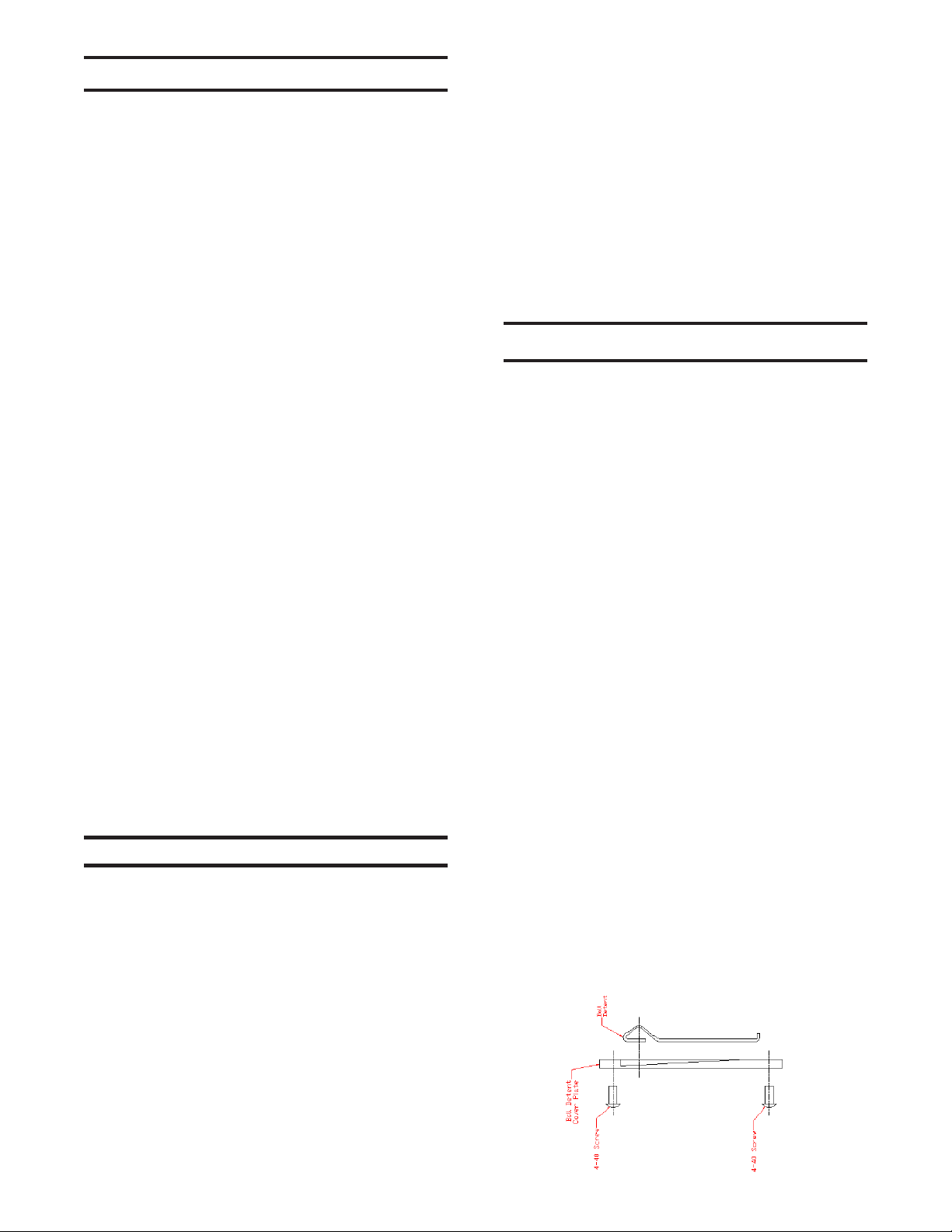
Tornado(tm)(Pat# 5791328) Valve Low Pressure, High
Efficiency Lightning(tm) Bolt(delrin) with Quick Release
Pin Javelin (tm) Barrel 45 Grip Ball Detent Built-In Vertical
Mount Sidewinder(tm)(pat pend) Vertical Pressure Reg.
Threaded Vertical Feed Adjustable Trigger (3 adjustment
points) Adjustable operating software, includes,
hammer drive, hammer release, bolt drive, bolt release,
Adjustable ROF, Warp feed drive, Ball drop sensor
optional, plus more. Adjustable Low Pressure
Pneumatics Reg. Pull Through Cleaning Easy
Disassembly & Low Maintenance Rugged Design Barrel
Plug Carrying Case

Power Source
The Excalibur(tm)(pat pend) uses a 9-volt battery stored
in the grip as its power supply. For maximum number of
shots and velocity stability you should only use high
capacity rechargeable batteries or lithium batteries. The
Excalibur’s(tm)(pat pend) circuit board is designed with
a special voltage regulator system to allow the use
standard alkaline batteries. For best performance it is
still better to use rechargeable or lithium batteries. We
are currently using high capacity Nickel-Metal Hydride
batteries, with great success. The velocity and the
feeding consistency of the Excalibur(tm)(pat pend) can
start to vary if the paintball maker is fired using a low
battery.
Installing a Battery:
Step 1: Make sure the marker is unloaded, de-gassed
and turned off. Remove one of the two screws holding
the grip panel on the left side of the marker. Rotate the
panel out of the way. Remove the 9-volt battery from the
battery cable. Make sure not to pull the battery cable
apart.
Step 2: Install the new 9-volt battery on the battery
cable and place it back into the grip frame. Make sure
no wires on the battery cable are pinched. Gently loop
the wiring and lay it on the side of the battery.
Step 3: Rotate the grip panel back into place. Then
replace the grip panel screw. Your Excalibur(tm)(pat
pend) is now powered and ready to use.
Air Supply
The Excalibur(tm)(pat pend) is designed to operate on
nitrogen, compressed air, and CO2. It requires a high
flow of CLEAN gas. (Over the many years I have played
I have never had a problem with CO2 being dirty, only
the compressed air at some tournaments.) Most nitrogen
systems, including preset regulators, will work well. The
Excalibur(tm)(pat pend) is supplied with a Sidewinder
(tm)(pat pend) regulator which has been designed to
work at the low pressure range in which the
Excalibur(tm)(pat pend) operates. The input pressure
to the Sidewinder(tm)(pat pend) regulator should be from
500 to 800 psi.
Air supplied at fields and tournaments is often dirty.
Scuba air is not always clean either. This dirty air is one
reason for paintball gun and regulator failure. Next time
your gun or regulator fails at a tournament, stop - before
blaming the manufacturer of the paintball gun or regulator,
and check your air supply. Some of this dirt eventually
ends up in the marker. Electronic markers with solenoid
valves are particularly vulnerable to dirt. For this reason,
we recommend a portable filter such as the Guardian(tm)
when filling your tank, even if your tank has a built-in
filter.
**The Sidewinder(tm)(pat pend) regulator is designed
for a maximum input pressure of 800 psi. It has been
designed specificaly for use with the Excalibur(tm)(pat
pend). It also works well with many other paintball guns.
Refer to the Sidewinder(tm)(pat pend) Reg. section of
this manual for more information. If you change out the
Sidewinder regulator, you will quickly discover that the
Sidewinder regulator is currently one of only two regs
that will keep up with the low operating pressure and
high flow demands of the Excalibur(tm)(pat pend). The
Palmer Stablizer is the only other regulator that will
work.**
**Use only steel braided hose and stainless steel quick
disconnects or Macro-line. Micro-line is inappropriate
and unsafe for use in paintball.**
**When attaching the air line make sure to blow the line
out with air before attaching it to the marker to make
sure the air line is clear of debris.**
**DO NOT USE TEFLON TAPE.**
**The use of pro-connects and fittings like those can
cause a drop in efficiency and can cause drop off
problems while firing the Excalibur(tm)(pat pend). They
are not a good fitting for low pressure guns.**
**When using CO2 it is a MUST that you keep liquid
CO2 out of the Excalibur(tm)(pat pend).**
If running CO2 on the Excalibur(tm)(pat pend) you must
use a tank with an anti-siphon tube. It is best to double
regulate by using a secondary regulator attached to the
bottom of the grip. AKALMP recommends the Palmer
Stabilizer. The Stabilizer’s output should be set at 500-
550 psi running into the Sidewinder(tm)(pat pend)
regulator which controls the velocity. Liquid must be
kept out of the Excalibur(tm)(pat pend).

Excalibur Notes
AKALMP is continuosly refining the Excalibur to push
its performance to the extreme. Here is a list of things
that have changed between the different batchs of
markers. This manual covers most things on the
Excalibur but be careful becuase there may be a change
that is not in this version of the manual yet. AKALMP
reserves the right to revise and improve its products as
it sees fit.
Serial numbers: 0 thru 57.
These are original production units. They have had the
circuit board and ram upgraded to the current version.
These Excaliburs also used the Spyder style ball detent
and non-threaded feed tubes.
Serial numbers: 58 thru 159.
Are equiped with the new circuit board and ram. They
have the new threaded feed tubes and other small
adjustments to set screw sizes to make assemble
easier. This version Excalibur uses the F-4 wire nubbin.
Serial numbers: 160 to present.
The barrel was moved back farther into the body by
about .125 to allow the paintball to be seated in the
barrel better. Set screw sizes were finalized. A few small
adjustments were made to the sizes of the air passages
to make the pneumatics more efficient. The bodies are
now completely finalized. The only thing left for the body
is the ball drop sensor which is being worked on. Any
tuning will now be in the cartridges themselves.
Febuary 21, 2001
A change in the Excaliburs valve spring was made. We
have changed it from a spyder style valve spring to a 98
cocker length spring. We have found this to help
effeciency and also lower the sound signature of the
marker more.
Notes:
As adjustments were made during production a few set
screw size changes, so be careful if you have to replace
one. Make sure it is the same size as the one removed.
The tube section of the valve chamber endcap is fine
the way it is, some may want to cut the sides out of the
tube section. We’ve tested that all ready and there was
no change in performance. Theres no need to cut the
sides out.
There is no need to cut grooves on the outside of the
ram and hammer cartridge. The air flow around the
cartridge is already high enough, if you cut grooves
around the outside you will only be slowing them down.
When the Excalibur is new the pneumatics reg needs
to be set at 90 to 100 psi. Once the Excalibur has had
a few cases of paint through it you can adjust the
pneumatics reg down around 70 to 80 psi.
Firing the Excalibur
Turning the Excalibur “ON” and airing it up:
Step 1: After making sure the marker is unloaded and
de-gassed, push the bolt fully forward.
Step 2: Turn the marker “ON” using the recesed power
switch. The raised screw on the back of the grip plate
next to the power switch indicates the “ON” position for
the switch. There is no LED light to indicate the marker
is on.
Step 3: Turn on the air source. If the bolt is not in its
forward postion it will now move forward closing the
breech. If air comes out of the barrel gently hold the bolt
back - this will allow the valve to seal.
Step 4: The paintball marker is now ready to use.
Step 5: Firmly grasp the grip, simply point and pull the
trigger
**Always keep your finger out of the trigger well
when you are not firing the paintball marker.**
Velocity Adjustment
The velocity of the Excalibur(tm)(pat pend) is controlled
directly through the Sidewinder(tm)(pat pend) regulator
mounted vertically in front of the trigger frame.
The Sidewinder(tm)(pat pend) regulator that comes with
the Excalibur(tm)(pat pend) is adjusted in this fashion:
1. Turning the adjuster screw clockwise will lower the
pressure, thus lowering the velocity.
2. Turning the adjuster screw counter-clockwise
will increase the pressure raising the velocity.
When making velocity adjustments you should use
extremely fine adjustments so as not to go past the
desired velocity. If you are unsure where your operating
pressure is, simply turn the pressure down until the
velocity drops to about 200 fps then slowly turn the
pressure back up.
**Do not exceed a
velocity of 300 FPS**

Cleaning and Maintenance
The barrel on the Excalibur(tm)(pat pend) can be cleaned
during a game by either unscrewing the barrel from the
marker or by removing the bolt and swabbing through
the marker and the barrel.
The bolt can be field-stripped from the Excalibur(tm)(pat
pend) while the marker is pressurized with gas. This
allows you to clean the marker and oil the bolt when
needed.
The Excalibur(tm)(pat pend) should be cleaned
externally using a cotton cloth and window cleaner or a
50% alcohol/water mixture.
All external and internal moving parts should be lubricated
using a light synthetic oil only. Oil can be added by
placing a few drops in the input quick disconnect on the
Sidewinder(tm)(pat pend) regulator and then dry firing
the gun. A few drops should also be placed on the o-
rings on the Lightning bolt. This should be done every
time you play, and the bolt should be oiled
throughout the day of play.
Recommended lubricants: Extreme-lube from AKALMP
or Palmer Pursuits paintball gun oil.
**Under no circumstances should you use Vaseline,
WD-40, Grease of any kind, Engine Oil, 3-in-1, gun
oils, and any similar oils. If you have a question
about the type of paintball gun oil you are using e-
mail us.**
The electronics are protected against moisture, but the
Excalibur’s(tm)(pat pend) electronic compontents should
never be immersed in water or damage may occur.
All the threads on the Excalibur(tm)(pat pend) are
American threads. All set screws are American sizes.
Excalibur(tm)(pat pend) maintenance schedule:
Though the Excalibur(tm)(pat pend) was designed to be
virtually maintenance free the Excalibur(tm)(pat pend)
will give you many years of use if normal maintenance
is done to the marker. Even if the Excalibur(tm)(pat
pend) does not need it, good maintenance will keep it
running properly for many years. Every time you play,
put a few drops of oil into the input quick disconnect on
the Sidewinder (tm)(pat pend) regulator.
Once a month, remove the cartridges and clean the
marker.
Every 25,000 cycles or 3 months:
Check the output pressure of the Pneumatics Reg.
Every 50,000 cycles or 6 months:
Inspect, and replace if needed, the Ram and hammer o-
rings.
Inspect the regulator seat on the pneumatics regulator
and the Sidewinder(tm)(pat pend) regulator for wear.
Inspect the Urethane bumper on the Ram and Hammer
for wear.
Every 75,000 cycles or 9 months:
Inspect, and replace if needed, the Ram and hammer o-
rings.
Inspect the regulator seat on the pneumatics regulator
and the Sidewinder(tm)(pat pend) regulator for wear.
Inspect the Urethane bumper on the Ram and Hammer
for wear.
Every 100,000 cycles or once a year:
Inspect the whole marker for any signs of problems that
could be starting.
If the Excalibur(tm)(pat pend) is to be stored for more
then two months, remove the valve spring. This will
increase the spring’s lifespan. It is a good idea to do
this with both hammer and valve springs on any paintball
gun that is to be stored for a long time.

Troubleshooting
Excalibur(tm)(pat pend) will not fire
Is there a battery in the Excalibur(tm)(pat pend)?
- See Power Supply.
Is there air/nitrogen or CO2 gas present?
- See Air Supply.
Was the compressed air or nitrogen clean?
Is the Excalibur(tm)(pat pend) turned on?
- See Power Supply.
Is the trigger adjusted correctly?
- See Trigger Adjustment.
Is the bolt jammed?
Is the pneumatics regulator working?
- See Pneumatics Reg.
Is the circuit board working?
- See Electronics.
Is the hammer dwell set correctly?
- See Electronics. Check for damaged wiring.
Velocity too Low or too High
Is output pressure from Sidewinder regulator set
correctly?
- See Sidewinder Reg.
Is hammer dwell adjustment set correctly?
- See Electronics.
Is hammer piston o-ring in good shape?
- See Hammer.
Is the pneumatics regulator set correctly?
- See Pneumatics Reg.
Is the battery fresh and new?
- See Power Supply.
Chopping paintballs
Is your hopper working correctly?
Is your bolt “OPEN” dwell set correctly
- See Electronics.
Is your ball detent working?
- See Ball Detent.
Is the pneumatics regulator set correctly?
- See Pneumatics Reg.
Is the battery fresh and new?
- See Power Supply.
Firing too slow
Is your rate of fire (ROF) set correctly?
- See Electronics.
Are the dwell settings correct?
- See Electronics.
Is the pneumatics regulator set correctly?
- See Pneumatics Reg.
Is the battery fresh and new?
- See Power Supply.
Excessive gas consumption
Is hammer dwell set correctly?
- See Electronics.
Is there a leak?
Gas leaking
Leaking from Tornado(tm)(pat # 5791328) valve?
- See Tornado Valve.
Leaking from Ram (pneumatic cylinder)?
- See Ram.
Leaking from Pneumatics Regulator?
- See Pneumatics Reg.
Leaking from Sidewinder(tm)(pat pend) Regulator?
- See Sidewinder Reg.
Leaking from Solenoid valves?
Electronic problems
Check battery power level.
- See Power Supply.
Check for damaged wiring.
Check circuit board dwell settings.
- See Electronics.

Custom Work
For the customers that want splash, custom color
anodizing and have custom mill work, there are versions
of the Excalibur(tm)(pat pend) available through our
authorized airsmiths that can be made into custom
markers. These markers are still covered under factory
warranty if the work is done by an authorized airsmith.
AKALMP will be doing a limited number of custom
Excaliburs. A complete list of our authorized airsmiths
can be found on our web site, akalmp.com.
If you wish to do the work yourself, or have non-factory
authorized airsmith do the work, please be careful. The
factory warranty will be void. When doing custom colors,
do not strip the hard anodized bodies, bare aluminum
bodies are available from AKALMP. The hammer tube,
hammer endcap, pneumatics regulator tube, ram tube
and ram endcap should not be stripped of their hard
anodizing. Doing so can cause wear. Striping the
anodizing from these pieces will void the factory warranty
on these pieces.
When doing custom mill work to the body of the
Excalibur be aware there are a few area that you should
stay away from and a few areas that have critical depths.
In the schematics section of this manual there are
drawings that specify the areas to be careful of when
doing custom mill work.
If you have a custom shop build a custom milled and
anodized Excalibur(tm)(pat pend) the gun body and feed
tube should be anodized seperately. Then use blue Loc-
tite when you screw the feedtube and body together.
On the rear of the Excalibur(tm)(pat pend) there are two
set screws, the lower of which is the hanging screw
hole for anodizing. Because anodizing requires an
electrical charge, the second set screw hole is provided
for a threaded electrode. The upper set screw is the
plug hole for the air passage.
Accessories
Warp Feed adapter:
This adapter replaces the standard threaded feed tube
with a new feed tube that will allow you to attach the
feed adapter for the warp feed system.
Part number: (available soon)
Programmer cable:
The adaptor that hooks to the Excalibur(tm)(pat pend)
and to your PC or laptop so you can adjust the timing
settings.
Part number: (available soon)
Tool Kit:
The tool kit contains the necessary specialty tools for
properly disassembling the Excalibur(tm)(pat pend).
Part Description: Part Number:
Pneumatics reg removal wrench
Hammer spanner wrench
Pneumatics reg tester
Pressure gauge
Ball Detent
The Excalibur(tm)(pat pend) has been supplied with a
ball detent to keep paintballs from double feeding. Since
the Excalibur(tm)(pat pend) is an electronically controlled
system, it does not require a ball detent but we thought
it would be a nice back up.
Replacement of ball detent:
The ball detent may become worn or broken over time.
This is normal. The standard Excalibur(tm)(pat pend)
uses an F4 wire nubbin. They are available through your
local airsmiths. Some custom Excaliburs(tm)(pat pend)
may have a different ball detent.
To replace the detent.
1. Remove the two 4-40 button head screws.
2. Lift the cover plate away from the body of the
Excalibur(tm)(pat pend).
3. Remove the detent and replace with a new one.
4. Re-install the cover plate and the two screws. Do not
over tighten, just snug them down.
Ball Detent Parts Chart:
Part Description: Qty: Part Number:
Ball detent cover plate 1
F4 ball detent 1
4-40 button head screws 2

Electronics
The Excalibur(tm)(pat pend) is controlled by a state of
the art software driven computer board. The newer design
runs the Excalibur(tm)(pat pend) at its true fire rate
capability unlike the original circuit board in the first 40
Excaliburs(tm)(pat pend). The board is equipped with
many features that are not found on other electronic
paintball markers. First the board is equipped with a
special voltage regulator system that will increase the
life span of the battery. The board is made with
connectors for every attachment necessary. No soldering
of wires is needed. If the trigger micro switch goes bad
just unplug it and replace with a new one. The same
goes for the battery plug, the on-off switch, and the
solenoid valves. There is also a programming port and a
recharging port. When using rechargeable batteries you
don’t have to remove the battery just use an adaptor
and recharge the battery. There is also a port that will
support a ball breech sensor, Warp Feed and an Intella
feed system. The circuit board is protected against
moisture,but do not immerse the Excalibur(tm)(pat pend)
in water. The Excalibur(tm)(pat pend) is tournament legal,
as the board operates in semi-automatic mode only.
***Warning any tampering with the circuit board
will cause it to erase the program from the
computer chip. The board would then have to be
reprogramed at the factory.***
Circuit board schematics:
Rate of Fire adjustment:
The only way for the Excalibur(tm)(pat pend) parameters
to be changed is through adjusting the software via a
computer. This does four things:
First, it allows for very fine adjustment to the dwell
settings. You can adjust each parameter a milliscond
at a time if you like.
Second, the gun can never go out of time because the
software cannot change during use.
Third, whenever there is an update, instead of having to
change the board you can just download the new
software.
Fourth, it makes the marker completely tournament legal
since there is no physical way on the board to adjust
the firing parameters.
The factory settings for the Excalibur(tm)(pat pend) make
the gun run at 10 BPS (balls per second). The marker is
capable of running 13 BPS but to run at 12-13 BPS
without any chance of ball breaks it will be best to wait
until the ball breech sensor is ready. With the sensor
option installed, the bolt will stay open only long enough
to allow a ball to drop into the breech. This will allow
maximum ROF (rate of fire) and eliminate any chances
of pinching balls at any ROF.
The factory dwell parameters:
Hammer drive: 12ms
The HAMMER DRIVE is the total amount of time that
the hammer solenoid stays turned on pushing the
hammer forward against the Tornado(tm)(Pat # 5791328)
valve thus also opening the valve and releasing air to
shoot the paintball.
Hammer release: 5ms
The HAMMER RELEASE is the amount of time after
the hammer is fired before the bolt is activated. It delays
the activation of the bolt, thus allowing the ball to clear
the barrel and eliminates blow back through the feed
tube.
Bolt drive: 55ms
The BOLT DRIVE is the amount of time that the bolt
solenoid stays turned on, thus controlling the time that
the bolt stays open allowing a ball to drop into the breech.
When the breech sensor is installed the sensor will over-
ride the bolt drive setting and close the bolt as soon as
a ball is detected in the breech.
Bolt release: 25ms
The BOLT RELEASE is the amount of time after the
bolt solenoid has turned off. This setting allows the bolt
to completely close and seal the ball into the barrel of
the marker. If this time is set too short the marker may
skip during high ROF’s and the effectiveness of the ball
shot will drop off. You should never have to change this
setting.
We have found that these numbers work the best and
will achieve around 11 rps. The bolt release dwell is not
a number that should be changed. If it is lowered you
will find that the marker will start over-lapping on the
bolt closing and the firing sequence of the marker.
The software will calculate the max rate of fire with the
dwell settings you have choosen. Then you have the
option of choosing a different rate of fire that falls within
the parameters of the max rate of fire. We are working
on pushing these numbers farther to make the marker
even faster. These numbers control the rate of fire of the

Excalibur(tm)(pat pend). You can change these numbers
directly or set them and then change the rate of fire
control.
Dwell adjustments:
To change the firing parameters of the Excalibur(tm)(pat
pend), first make sure the marker is unloaded, de-
gassed and turned off. Plug the programmer cable into
your computer. Then remove the cover plate on the left
side of the grip plate. Gently plug the cable into the
connector on the circuit board. Load the manual and
start the “parameters adjusting” program. Turn the
Excalibur(tm)(pat pend) back on. Change the dwell
settings you want and load the new dwell settings into
the Excalibur’s(tm)(pat pend) circuit board. Turn the
Excalibur(tm)(pat pend) off. Unplug the marker from the
computer cable and test the marker to make sure that
the settings are working the way you want them to.
Warp Feed and Intella feed:
The Warp Feed and Intella Feed port allows you to attach
the Warp Feed system from Air Guns Deisgns and/or
an Intella Feed style system. If a second board is
designed to go into a VL loader that will use the same
signal as the Warp Feed system but run the VL loader
off of its own power supply this will give you an Intella-
feed system.
Trouble shooting:
Most circuit board problems can be traced back to the
installation of the wrong software when adjusting the
marker’s settings. If after adjusting the settings you
encounter slow or no cycling, double check circuit board
to make sure you haven’t selected the wrong marker
setting.
Removing the circuit board:
To remove the circuit board simply remove the two
screws holding the grip frame and grip plate onto the
marker body. Then carefully pull the grip assembly
straight away from the marker body. There are two
locating pins in the grip plate so the grip plate and grip
cannot move sideways. This is why the grip assembly
must be pulled straight away from the marker. Then
carefully unplug the two solenoid valves from the
connector sockets on the circuit board. Place the marker
body to the side. Remove the three plastic screws that
hold the circuit board to the grip plate. Carefully lift the
circuit board out of the grip plate. Unplug the three plugs
from the connector sockets that are for the trigger switch,
battery connector and on-off switch.
When plugging the connectors back in, the order from
the back end of the board moving forward is as follows.
The on-off switch, then the battery, and finally the trigger
switch.
When connecting the solenoids the three pin connector
is the bolt and the two pin connector is the hammer.
Be careful not to pinch or bind the wires. On the battery
cable it is best to make a loop and then lay the loop on
the side of the battery. This will reduce the movement of
the battery and keep the wires from getting damaged.

Hammer
Mechanical Hammer adjustment:
There is no mechanical adjustment to the hammer itself.
Simply screw the hammer cartridge in until it stops
against the body.
Hammer maintenace:
The o-ring on the hammer piston is sized to maintain a
constant fricton to the inside of the bore of the hammer
cartridge. Keeping a constant fricton on the bore is
important to keep a consistent velocity. If the o-ring
wears out, the fricton will change and in turn change the
consistency of force with which the hammer strikes the
valve. So, it is important to keep that o-ring in good
order and properly oiled.
To pull the hammer cartridge out of the marker: Use a 5/
32 allen wrench and unscrew the hammer cartridge.
Then gently pull it out the back of the Excalibur(tm)(pat
pend).
Use the hammer spanner wrench and an allen wrench
to loosen the hammer endcap. Unscrew the endcap
from the hammer cartridge and gently pull pieces apart.
You can now replace the majority of o-rings and u-cups.
Re-assemble in reverse order.
Carefully re-install everything and tighten down the
hammer endcap. Be careful not to over-tighten. Make
sure the -013 o-ring on the endcap is in good condition.
It will keep the nose from coming loose. You will also
want to put a small drop of BLUE Loctite on the threads
as you re-assemble the hammer cartridge.
Trouble shooting:
Air leaking from solenoid:
1. Check the solenoid valve, it may need to be replaced.
2. Check the hammer piston o-ring. Air may be leaking
around it. If air is leaking around it, replace the hammer
piston o-ring.
Air leaking around the front of the hammer:
1. Check the u-cup. It may need to be replaced.
2. Check the o-rings on the outside of the cartridge.
Hammer Parts Chart:
Part: Qty: Part Number:
Hammer Weight 1
Hammer Endcap 1
Urethane bumper 1
-013 o-ring 1
-015 o-ring 1
7/16x.093 u-cup 1
Hammer Plate 1
Hammer Shaft 1
-010 o-ring 1
Urethane bumper 1
Hammer tube 1
-015 o-ring 4
5/16-24 1
Lightning Bolt
The only part on the Excalibur(tm)(pat pend) that may
experience any possiblity of wear is the Lightning bolt
and pull pin. That is the intended design of the bolt. The
bolt is made of Delrin to help save wear and tear on the
gun body. Paintball gelatin is actually very abrasive and
can cause wear on the bolt. The pull pin is designed
with two flats milled on it. These two flats fit into the H-
bar on the ram, this design reduces wear on the pin.
To remove the bolt:
Pull the bolt pull pin knob straight up from the bolt and
gun body. The pin is designed to stay in the bolt. Then,
slide the bolt out the back of the marker. To install the
bolt, slide it all the way forward into the marker; then

push the bolt pull pin down until it latches into the H-
bar.
The screw in the back of the bolt adjusts the tension
and locking of the bolt pull pin. You should not have to
adjust this. But, if you do, adjust the ball plunger in until
you cannot pull the bolt pull pin up. Then slowly back it
off until the pin moves at the desired tension. Do not
adjust the tension too far out or the pin can come loose.
Trouble shooting:
Pull Pin stuck:
1. Check the ball plunger in the back of the bolt, it may
be stuck.
Bolt not sliding smoothly:
1. Check the o-rings on the bolt to make sure they are
not swollen. Replace them or properly oil them.
Bolt Parts Chart:
Part Description: Qty: Part Number:
Black delrin L. bolt 1
-015 o-rings 2
-013 o-ring 1
ball plunger 1
pull pin 1
pull pin knob 1
Other Component Parts
Vertical Feed Tube:
Excaliburs(tm)(pat pend) with serial numbers from 0 to
57 have press-fit feed tubes. The early Excalibur(tm)(pat
pend) feed tubes are held in with GREEN Loc-tite.
Excaliburs(tm)(pat pend) from serial number 58 and up
have a new threaded feed tube. AKALMP designed a
new threaded feed tube that would hold up to the
stresses of playing paintball. The new threaded feed
tubes are held in place with BLUE Loc-tite. They have a
different thread pattern than the Angel feed tubes.
The Excalibur uses a short feed tube that does not have
any problems feeding paint at a high rate of fire as long
as you hopper is fast enough. If you want a long feed
tube you can order one from your local airmsith or from
AKALMP.
Lightning bolt Pull Pin Knob
The knob on the pull pin is machined from aluminum
and pressed onto the stainless steel pin. This allows
the knob to be anodized to the same color as the gun.
Air Passage Set Screws
The set screws on the air passages should be secured
with GREEN Loc-tite so they stay in place under
pressure. All threads on the Excalibur(tm)(pat pend) are
American thread sizes.
Pnuematics Regulator
The pneumatics regulator controls the air pressure fed
to the solenoid valves, which in turn operate the rest of
the gun. The maximum operating pressure of the
solenoid valves is 120 psi., but the components of the
Excalibur(tm)(pat pend) need only 90-100 psi to operate.
Use of the pneumatics regulator keeps the solenoid
valves from receiving too high a pressure, and will keep
them operating properly for many years.
The pneumatics regulator is preset to 90-100 psi at the
factory and should not need adjustment. If a replacement
regulator is installed you need to check the pressure,
but it should be at 90-100 psi from the factory. The
regulator cartridge can be removed from the
Excalibur(tm)(pat pend) without causing the pressure
settings to change. The adjuster screw is on the front
side of the regulator and should never be adjusted on
the field or by a non-qualified person.
**This regulator stores air in the marker when the
gas source is shut off. The stored gas is enough to
cycle the gun one or two times.**
**The pneumatics regulator should be set at 90-
100 psi. output.**
**Do not adjust the pressure without a gauge, you
can easily over- pressurize the system and damage
the solenoid valves.**
**Do not install an external adjusting knob, this is
an illegal way of adjusting the velocity. If an
Excalibur(tm)(pat pend) is sent in for repairs with
an external adjusting knob installed, it will be
removed and you will be charged for replacement
of the pneumatics regulator core. THE KNOB WILL
NOT BE SENT BACK.**
To adjust the regulator:
1. De-gas the marker.
2. Unscrew the hammer cartridge from the back of the
marker.
3. Install the pneumatics regulator test chamber into
the hammer tube. Then install the low pressure gauge
on the test chamber.
4. Gas up the gun to 200 psi from the Sidewinder(tm)(pat
pend) regulator and check the pressure. Using an allen
wrench, adjust the regulator core clockwise to lower
the pressure and counter clockwise to raise the
pressure. You will have to cycle the marker while you
adjust the regulator to get the pressure to change. The
adjustment is very sensitive.
5. Once the correct pressure is achieved, turn the air on
and off and cycle the marker several times to make
sure the pneumatics regulator stays at the new setting.
Disassembly of the Pneumatics Reg:
1. Using the pneumatics reg. removal tool, unscrew the
pneumatic reg from the front of the Excalibur(tm)(pat
pend).
2. Gently clamp the Pn-reg body between the two pieces
of wood.
3. Use the pneumatic reg removal tool and a wrench
and break the BLUE Loc-tite seal between the two halves.
4. Unscrew the pn-reg endcap. Remove the reg-washer
and o-ring from the end of the pn-reg body. You can also
unscrew the reg core from the pn-reg endcap through
the back of it, but not through the front.
5. Using snap ring pliers remove the snap ring from the
end of the pn-reg body.
6. Gently push the reg psiton and spring out of the pn-
reg body using something soft like a plastic ball point
pen which will not damage the sealing area of the
regulator piston.
7. You can now replace all o-rings and springs, if needed,
and reassemble in reverse.
**There are two sides to snap rings and it is
important which side faces out of the pn-reg body.
One side has squared off, sharp edges and one
side has edges that are rolled over. When installing
the snap ring make sure the sharp square edge
faces to the outside of the pn-reg body.**
Trouble shooting:
Air leaking from the front of the regulator:
1. Check the o-rings around the reg-core.
Pneumatics Reg Parts Chart:
Part: Qty: Part Number:
Reg endcap 1
-015 o-ring 1
-013 o-ring 1
Reg core 1
-010 o-ring 2
10-32 set screw 1
Reg washer 1
Reg body end 1
-008 o-ring 1
-015 o-ring 2
Reg piston 1
reg spring 1
-013 o-ring 1
9/16 internal snap ring 1

Pneumatic Ram
Removal of Pneumatic Cyclinder (ie: the Ram):
De-gas the marker and remove all paint. Remove the
bolt, the body endcap, and pneumatics regulator. Then
remove the set screw pin that holds the ram in place.
Using a 1/2" dia wood dowel rod, gently push the ram
out through the back of the marker body.
Disassembly.
Insert a 1/4" dia metal rod in the set screw pin hole. You
may have to polish the 1/4" rod just a little to get it to fit
properly. Then, using an adjustable wrench, unscrew
the front nose from the ram tube by using the 1/4" dia
rod to turn the ram tube. Pull the two halves apart. You
can now replace most of the O-rings and U-cups if need
be. To remove the H-Bar use the end of the pneumatics
reg tool that fits holes on the H-bar and clamp the back
end of the ram between two pieces of wood or in a 3/8"
collet. Reassemble in reverse and tighten down gently.
You must use a small drop of BLUE Loctite on the threads
to keep everything tight. When you re-install the ram it
is a must that you use BLUE loc-tite on the ram retaining
pin threads to keep it from coming loose when the gun
is in use. Do not over-tighten the pin.
**Be careful not to damage the ram piston o-ring
when you re-install the ram shaft into the ram
tube.**
Trouble shooting:
Air leaking from solenoid:
1. Check the solenoid valve, it may need to be replaced.
2. Check the ram piston o-ring. Air may be leaking
around it. If air is leaking around it, replace the ram
piston o-ring.
Ram Parts Chart:
Part Description: Qty: Part Number:
Ram tube 1
-015 o-ring 5
Ram Shaft 1
Urethane bumper 1
-010 o-ring 1
Ram Plate 1
Ram Encap 1
-015 o-ring 1
7/16x.093 u-cup 1
-013 o-ring 1
Urethane bumper 1
H-bar 1
Ram Retaining Pin 1
Screws and O-Rings
Serial # 0 thru to present.
3.5x.9mm
-008
-010
-013
-015
7/16x.093 u-cup
Sidewinder o-rings:
-008
-010
-015
-017
-113
Excalibur Screws & Pins:
Serial # 0 to 57.
Quanity..............Type
3..............5/16-24 x .250 Set screws (endcaps)
1..............5/16-24 x .3125 set screws (valve)
2..............10-32 x 1.150 Button head (grip)
4...............6-32 x .250 Button head (grip panels)
1.............10-32 x .375 set screws (trigger stop)
1..............8-32 x .625 Set screws (trigger stop)
1..............8-32 x .437 set screw (trigger stop)
1..............6-32 x .250 set screw (trigger stop lock)
1..............10-32 x .375 button head (grip plate/
frame)
4..............4-40 x .5 button head (solenoid valves)
2..............4-40 x .250 button head (detent cover
plates)
4..............4-40 x .187 button head (electronics
cover plates)
2.............10-32 x .1875 set screw (air passage plug,
pn-reg core)
1..............5/16-24 x 1.125 set screw (ram pin)
3..............4-40 x .250 plastic flat head screws (circuit
board)
3..............2-56 x .1875 cap head screws (on-off
switch)
1..............6-32 x .500 set screw (air passage plug)
1..............1/4-28 x .1875 set screw (anodize hole
plug)
1..............1/4-28 x .500 set screw (air passage plug)
2..............1/8 x .750 pins (grip alignment pins)
1..............1/8 x .750 pin knurled on end (trigger pivot
pin)

2..............6-32 x .125 set screw (air passage plug)
1..............6-32 x .500 set screw (air passage plug)
1..............1/4-28 x .1875 set screw (anodize hole
plug)
1..............1/4-28 x .500 set screw (air passage plug)
2..............1/8 x .750 pins (grip alignment pins)
1..............1/8 x .750 pin knurled on end (trigger pivot
pin)
2..............2x18mm pins (micro-switch pins)
Serial # 58 to 159.
Quanity..............Type
2..............5/16-24 x .250 Set screws (endcaps)
2..............5/16-24 x .3125 set screws (endcaps and
valve)
2..............10-32 x 1.000 Button head (grip)
4..............6-32 x .250 Button head (grip panels)
1..............10-32 x .375 set screws (trigger stop)
1..............8-32 x .625 Set screws (trigger stop)
1..............8-32 x .437 set screw (trigger stop)
1..............6-32 x .250 set screw (trigger stop lock)
1..............10-32 x .375 button head (grip plate/frame)
4..............4-40 x .5 button head (solenoid valves)
2..............4-40 x .250 button head (detent cover
plates)
4..............4-40 x .187 button head (electronics cover
plates)
2..............10-32 x .1875 set screw (air passage plug,
pn-reg core)
1..............5/16-24 x 1.125 set screw (ram pin)
3..............4-40 x .250 plastic flat head screws (circuit
board)
3..............2-56 x .1875 cap head screws (on-off
switch)
2..............8-32 x .125 set screw (air passage plug)
1..............6-32 x .500 set screw (air passage plug)
1..............1/4-28 x .1875 set screw (anodize hole
plug)
1..............1/4-28 x .500 set screw (air passage plug)
2..............1/8 x .750 pins (grip alignment pins)
1..............1/8 x .750 pin knurled on end (trigger pivot
pin)
2..............2x18mm pins (micro-switch pins)
Serial # 160 thru to present.
Quanity..............Type
4..............5/16-24 x .3125 set screws (endcaps &
valve)
2..............10-32 x 1.000 Button head (grip)
4..............6-32 x .250 Button head (grip panels)
1..............10-32 x .375 set screws (trigger stop)
1..............8-32 x .625 Set screws (trigger stop)
1..............8-32 x .437 set screw (trigger stop)
1..............6-32 x .250 set screw (trigger stop lock)
1..............10-32 x .375 button head (grip plate/frame)
4..............4-40 x .5 button head (solenoid valves)
2..............4-40 x .250 button head (detent cover
plates)
4..............4-40 x .187 button head (electronics cover
plates)
2..............10-32 x .1875 set screw (air passage plug,
pn-reg core)
1..............5/16-24 x 1.125 set screw (ram pin)
3..............4-40 x .250 plastic flat head screws (circuit
board)
3..............2-56 x .1875 cap head screws (on-off
switch)
2..............8-32 x .125 set screw (air passage plug)
1..............8-32 x .500 set screw (air passage plug)
1..............1/4-20 x .1875 set screw (anodize hole
plug)
1..............1/4-28 x .500 set screw (air passage plug)
2..............1/8 x .750 pins (grip alignment pins)
1..............1/8 x .750 pin knurled on end (trigger pivot
pin)
2..............2x18mm pins (micro-switch pins)
Sidewinder Regulator
The Sidewinder(tm)(Pat Pend) regulator was designed
specificaly for use on the Excalibur(tm)(pat pend)
because of its extremely low operating pressure of
aproximately 140-150 psi. This regulator will work well
on other guns,also. The design of the regulator permits
the air hose to be connected to the gun in any location
the user wishes within a 360 degree circle around the
base of the reg, while still allowing the regulator to be
externally adjusted from the bottom. The top endcap of
the regulator can be replaced with different length ones
to allow the user to adjust total length of the reg.
**If you change out the Sidewinder(tm)(pat pend)
regulator, you will quickly discover that it is
currently one of only two regs that will keep up
with the low operating pressure and high flow
demands of the Excalibur(tm)(pat pend). Currently
the Palmer Stablizer is the only other regulator
that will work. **
Sidewinder(tm)(pat pend) Specifications:
Model: Sidewinder(tm)(pat pend)
Version:B
Gas Source: Compressed air, Nitrogen or CO2
Length: 4.875 inches
Width: 1.00 dia main body/1.125 dia swivel sleeve
Weight: .308 lbs (With quick disconnect)
Externally Adjustable Output Pressure: 0-700 PSI
Input pressure: 400-800 PSI
Adjusting the Sidewinder(tm)(pat pend) Regulator:
Decrease output:
Looking at the regulator from the bottom, turn the allen
wrench clockwise to decrease the pressure.
Increase output:
Looking at the regulator from the bottom, turn the allen
wrench counter clockwise to increase the pressure.

Dead Zone:
Since the Sidewinder(tm)(pat pend) regulator was
designed to go down to zero psi output, there is space
after it reaches zero that the adjuster screw can be
turned farther. If you turn the adjuster screw gently until
it bottoms out, then it will be 4 to 5 turns counter
clockwise until the pressure starts to rise again. This is
the dead zone.
Side Notes and Trouble Shooting:
Remember to shoot the gun several times after any
adjustment to the Sidewinder(tm)(pat pend) regulator
so you can make sure the velocity stabilizes.
If the regulator creeps in pressure range, check to make
sure there is not a piece of debris inbetween the regulator
seat and the regulator piston. If it continues to creep
replace the reg core.
When using the Sidewinder(tm)(pat pend) with CO2 you
will have to oil the regulator on a more regular basis.
The CO2 carries the oil away from the moving parts
quicker then nitrogen does.
Make sure the vent hole on the side of regulator body
middle is open and clean. If it is plugged the regulator
will not fuction properly.
The Sidewinder(tm)(pat pend) regulator is only designed
for a maximum input pressure of 800 psi.
Use only steel braided hose and stainless steel quick
disconnects. Mirco-line and Macro-line is inappropriate
and unsafe for use in paintball.
When using CO2 it is a must that you keep liquid CO2
out of the Excalibur(tm)(pat pend).
Disassembly of Sidewinder(tm)(pat pend)
Regulator:
To properly disassemble the Sidewinder(tm)(pat pend)
regulator and not scratch the outside, you will need a
few items: Two pieces of 2x4s about 4 inchs long, a
cloth strap wrench which can purchased at a hardware
or automotive store, a bench vise, a good adjustable
wrench and a set of allen wrenches. The strap wrench
can be used on many different things outside of paintball
so its handy to have around. Just follow the instructions
and it will be easy.
1. Remove all air sources. 2. Clamp the reg. body upper
and reg. middle between the two pieces of wood. The
wood will keep the regulators outside surface from getting
scratched up. 3. Using the adjustable wrench on the
swivel nut un-screw the swivel assembly from the bottom
of the regulator. Once loose, unscrew the two pieces.
Be careful not to lose the reg. washer that is inside this
portion of the regulator. 4. Reclamp the regulator between
the two peices of wood, clamp on the reg. body upper.
Using the strap wrench loosen the reg. body middle
from the reg. body upper. Inspect the o-rings for damage
or wear. Replace if needed. 5. Once the two halves are
separated you can remove the piston and springs from
the regulator body middle. Be careful not to damage the
piston or the o-rings. Remember in what order the parts
came out of the regulator. Replace o-rings or springs if
needed. 6. To disassemble the swivel joint, clamp the
threaded end of the swivel between the two pieces of
wood. Use the adjustable wrench to loosen the swivel
nut. The swivel nut is BLUE LOCTITED in place. 7. Using
a gentle twisting action gently pull the swivel sleeve
from the regulator body lower. Inspect the o-rings for
damage or wear. Replace if needed. 8. Use an allen
wrench and unscrew the regulator core from the regulator
body lower. The core comes out through the front of the
regulator body lower. Do not try backing it out. Be careful
not to damage any o-rings. If needed replace the o-
rings or if the reg. seat is damaged replace the whole
core assembly. 9. You can now replace the major
components to the regulator if needed. The regulator
goes back together easily. Use the strap wrench to
tighten. Do not over-tighten, just snug down and use a
drop of blue loc-tite on the threads of the swivel nut to
keep it tight.
Sidewinder(tm)(pat pend) Parts Chart:
Sidewinder(tm)(pat pend) Regulator:
Part: Qty: Part Number:
Sidewinder(tm)(pat pend) Reg 1
Regulator body upper 1
-017 o-ring 1
-015 o-ring 1
Regulator body middle 1
-008 o-ring 1
Regulator piston 1
-113 o-ring 1
Belleville springs 8
Regulator washer 1
Regulator Sleeve 1
-017 o-ring 2
Male Quick Disconnect 1
Regulator body lower 1
-017 o-ring 1
Regulator core 1
-010 o-ring 2
10-32 cap screw 1

Solenoid Valves
Removal of the solenoid valves:
Remove the grip frame and grip plate as one piece.
Carefully pull the grip and grip plate straight away from
the body. The grip plate locates on two pins in the marker
body.
Carefully unplug the solenoid valves from the circuit
board. Using an allen wrench, remove the screws holding
solenoid valve you want to replace. Lift the valve straight
out of the marker body. Be careful not to lose the small
o-rings that seal the solenoid to the body.
Place the o-rings back into the o-ring grooves on the
body. Place the correct solenoid valve on the solenoid
valve mounting bosses and tighten down screws. The
hammer solenoid valve cannot be installed in the bolt
socket and the bolt solenoid valve cannot be installed in
the hammer socket. Do not over tighten the screws.
Plug the solenoid valve back into the circuit board and
gently put the grip frame back onto the marker making
sure not to pinch any wires. Re-install the grip frame
screws.
The solenoid valves used in the Excalibur(tm)(pat pend)
are a custom version of an off the shelf valve and have
been thoroughly tested for long life and durability. A set
of valves used in the Excalibur(tm)(pat pend) paintball
marker have been tested to over 5,500,000 cycles and
are still running. 5,500,000 cycles is equivalent to
shooting 2750 cases of paint if the cases were 2000rd
boxes each. One randomly picked valve cycled over
20,000,000 times.
Do not try to work on the solenoid valves. Do not try to
exchange parts from one solenoid to another. The parts
on the solenoid valves are matched to each other when
they are assembled at the factory and can not be mixed
with other valves. If the solenoid valves parts are mixed
they may not work properly.
Trouble shooting:
Air leaking from the solenoid valve:
1. Check the o-rings sealing the valve to the body.
2. Check to see if the air is leaking through the solenoid
valve. If air is leaking through the valve, replace the valve
or check the o-rings of the hammer or ram.
Trigger Frame
Adjusting the trigger pull:
There are 3 set screws for adjusting the total trigger
movement: (1) forward stop, (1) rearward stop and (1)
mirco-switch activation screw.
When adjusting the trigger, start with the forward and
rearward trigger stops. Adjust the trigger until you have
the amount of movement you want. Then adjust the
mirco-switch screw until it activates the mirco-switch
during the trigger pull. Make sure to use a small amount
of BLUE Loc-tite to keep the set screws from coming
loose. Whenever you make any adjustments to the
trigger you should always make sure the mico-switch
activates when you pull the trigger.
**Do not remove the trigger spring. Always leave a
spring in the trigger to provide positive trigger
return.**
When adjusting the spring tension on the trigger, it is
best to leave the tension a little high so normal
movement during play will not accidentally activate the
trigger. The spring can be interchanged with those used
on Autococker trigger plates so you can personalize it
to your own spring tension.
**Do not cut the trigger guard off.**
Double triggers and frames are available from AKALMP
/ Leads Metal Products Inc. There is no difference in
the cost of the Excalibur(tm)(pat pend) for single or double
trigger frames. The two style of frames can be inter-
changed without any modifications to the gun.
Trouble shooting:
1. The electronics are on but the gun won’t fire. Check
to make sure that none of the trigger set screws have
moved out of adjustment.
Grip frame and trigger Parts Chart:
Part: Qty: Part Number:
Grip frame (single trig.) 1
single trigger 1
6-32 set screw 1
8-32 set screw 2
10-32 set screw 1
1/8 dia pin 3
6-32 button head screws 4
10-32 button head screw 1
grip panels 2
Grip Frame (double trig.) 1
double trigger 1

Tornado Valve
The valve used in the Excalibur(tm)(pat pend) is also
used in the Merlin body kits and other future markers.
The valve is a bigger, stronger Tornado(tm)(pat #5791328)
valve which was orginally designed for the cockers. The
Tornado(tm)(pat #5791328) valve has a lifetime warrenty
that covers replacement of the valve unless you modifiy
the valve.
Valve removal and maintenance:
Remove the valve chamber plug by unscrewing it from
the marker body using an allen wrench. Then slide it
out. The valve spring and valve stem should come out
with it. This will allow you to change the valve stem if
there is a problem.
To remove the valve body:
With the valve chamber plug, valve spring and valve stem
removed. Unscrew the hammer from the back of the
Excalibur(tm)(pat pend). Then unscrew the set screw
on the side of the marker that holds the valve body in
place. Using a wood dowel rod, gently push the valve
body out either end of the marker. When reinstalling the
valve body, use a drop of BLUE Loc-tite on the set screw
that holds the valve body in the marker.
Trouble shooting:
Air leaking down the barrel:
1. Check the valve stem, it may need to be replaced.
2. Air may be leaking by the o-ring on the valve body.
Take the correct size allen wrench and loosen the valve
retaining set screw about a 1/4 of a turn. If the leak
stops, tighten the screw back. What happens is that
the o-ring sometimes shifts just a little and loosening
the screw allows it to shift back.
Tornado Valve(tm)(Patent #5791328) Parts Chart:
Part: Qty: Part Number:
Valve Chamber endcap 1
-015 o-ring 1
5/16-24 set screw 1
Valve Spring 1
Valve Stem 1
Valve Body 1
-015 o-ring 2
Other manuals for EXCALIBUR
1
Table of contents