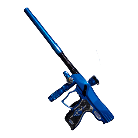
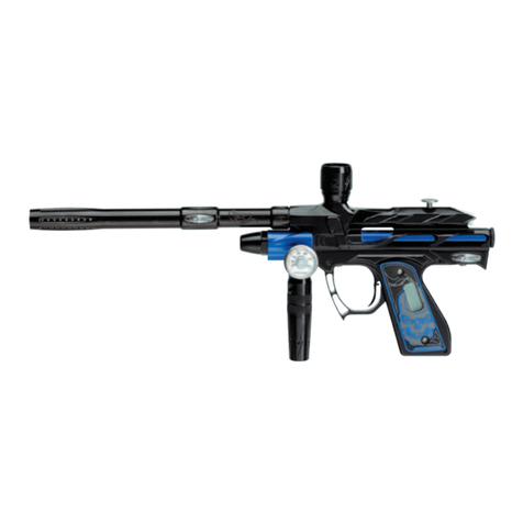
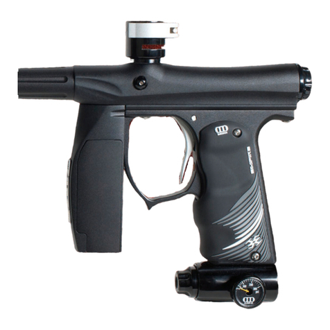
Alien Independence User manual

Independence
By
Warning:
Paintball markers are dangerous pieces of sporting equipment. Like any air rifle or air
pistol, it can cause injury or death.
By purchasing this paintball marker you assume all liability. Alien Paintball Equipment,
INC. (Alien) assumes no liability for its use, misuse, injury or death. Please follow all
federal, state and local ordinances.
Remember it is the “unloaded” gun that hurts people.
Independence retains air even after the bottle has been removed. It can retain a charge
for hours or even days after the bottle has been removed. Before removing protective
eyewear always check and double check that there are no balls in the chamber and that
the marker has no air pressure.
Risk of injury, especially blindness, can be greatly reduced by proper use and handling.
It is of the utmost importance that user and everyone within 300 feet of the marker have
proper paintball goggles on at all times. Some “finned” paintballs can increase this
distance to over 500 feet.
Always have a safety plug in, or a safety sock on, between uses. Always put on a
paintball-approved safety goggles before uncovering barrel. Always cover the barrel
before removing safety goggles.
Eyes are not a safety feature! Eyes limit ball breakage. The gun will fire regardless
of the LED color!

Table of contents
Safety………………………………………………………………………… 3
Limited warranty…………………………………………………………….. 4
Operating design……………………………………………………………. 4
Specifications ........................................................................................ 5
Operation, Air, Nitrogen, CO2, Barrels and Accessories,
Hopper and Paint. Power. Firing Modes………………………................. 6
Dwell, LPR, and Inline Regulator Adjustments ...................................... 7
Maintenance ........................................................................................... 9
Setting Trigger Pull…………………………………………………………. 10
Low Pressure Regulator (LPR) ............................................................. 11
High Pressure Regulator (Inline) ........................................................... 12
Disassembly …………………………………....................................…… 13
Reassembly…………………………………….................................….… 15
Software ……………………………................................................……. 18
On/Off, Forced Shot, Eyes, LED ColorsBattery Indicator, Lock ............................. 18
Demonstration and Training Mode, Firing Modes .........………........................……19
Quick Start Modes, Settings for Modes .............................................................… 20
Resetting to Factory, Programming Modes……….…......................………………. 22
Changing Settings ………………………….………………...............………….. 23
2

Safety
The first rule of paintball is: Safety First! Paintball markers propel a paintball at
speeds fast enough to cause blindness, even with the barrel removed or at the
lowest operating pressures.
Do not play or allow others to play or watch without wearing goggles designed
specifically for the sport of paintball. Never allow anyone to lift his or her goggles
while a gun is capable of firing. Goggles can fog over, paint can reduce vision
and some may be tempted to clean or adjust their goggles during play. Do not
ever let this happen for any reason.
•Play only at commercial playing fields. Proper fields will have a Chronograph,
referees and clearly marked safety areas. Chronograph your marker before every
game at the field’s safety limit, usually about 280 feet per second.
•Ramping (shooting more than one ball per trigger pull) dramatically increases the
chance of goggle lens failure or goggle dislodgement. Increased safety risks
outweigh any perceived advantages of ramping. Goggle manufactures
recommend replacement of goggle lenses after a direct hit. Alien advises against
the use of ramping modes. Notwithstanding this, ramping is included because
some tournaments specify ramping.
•You will be held liable if someone is hurt from a paintball shot from your marker.
Make sure you shoot at safe velocities and that everyone has proper eyewear.
•Never point the marker at anyone not wearing goggles.
•Remover the barrel and bolt before looking into the firing chamber and wear
goggles or approved safety eyewear
•Use extra caution when the bolt is removed as a ball, or part of a ball, shell can
fire out of feed neck or back of marker.
•Read the entire manual before operating the marker. The LPR should not be
adjusted until the player has read the LPR section
•Repair of a marker while pressurized increases risk of injury and should be done
only by those qualified in the art of airsmithing.
•Do not gas up marker with LPR cap off. The LPR piston will shoot out of the gun
at very high speeds if the cap is removed. Only experienced airsmiths should
service the LPR piston’s O-Rings or seal.
•Servicing the marker should not be done while the gun is in Response mode or a
Ramp mode.
•Turn off marker when operation is not desired.
3

Congratulations on your purchase of the Independence paintball marker by:
We believe it to be the best paintball marker available today and the best value.
Limited Warranty: Alien warrantees the Independence against defects in
manufacturing for a period of One Year from date of purchase. Copy of sales
receipt must be included for all warranty work. Pneumatic valves (solenoids) are
not made by Alien and are not coved either by their maker or by Alien. Warranty
on wiring harnesses is limited to defects in manufacturing.
Misuse, abuse or alteration of the marker voids the warranty.
Alien will pay for return shipping costs only on warranty work. Owners will pay
shipping to Alien for warranty work. Owner will pay shipping costs for both
directions on non-warranty work.
Operating Design: The Independence is an open bolt, pneumatic ram
design, yet it is a design distinct to Alien. Alien places the solenoid on the ram,
and then places the ram and solenoid module on the trigger frame. The constant
air supply is attached directly to the ram. This “Independent Ram” eliminates the
torturous air paths cut into the body and the lengthy additional hoses. The
resulting shorter air passages equates to faster cycling times. The design of the
ram housing outside the gun body provides a smaller, tighter, lighter marker and
one that has a unique and appealing look.
Alien also utilizes a patented “Sweep Valve” and “Sweep Bolt” to minimize
turbulence and to cause the air to flow under and around the ball. The resulting
“Sweep Trajectory” improves accuracy. The ball is no longer poked out of the
gun, rather swept on a rotating expanding pulse of air towards its destination
A brief use of the Independence will show its improved trajectory, that it is fast,
reliable, comfortable to hold and easy to aim and shoot. By taking a new path
Alien is "Light-years Ahead”.
4

Independence Specifications: Several configurations are listed to
help when comparing markers.
Weight: 1 lb. 6.9 oz. without barrel, high pressure regulator, bottle
adapter or battery
1 lb. 12.6 oz. with battery, regulator and bottle adapter
2 lb. 0.1 oz with Alien’s Mayday barrel attached
Length 8 inches - back of the trigger frame to the front of the body
9.5 inches - back of the trigger frame to the tip of the LPR
21 inches - to the tip of the Mayday barrel
Height 2.5 inches - top of the gun body to opening for the trigger
guard (two tubes & top rail of the trigger frame)
7.5 inches - top of the riser to the bottom of the trigger grip
8.5 inches - top of the riser to bottom of bottle adapter
Effective Range 200+ feet with excellent accuracy – paintballs will still break
on opponents at over 300 feet
Ball detents Dual Spyder type rubber catch bumpers
Power Nine volt. Alkaline batteries are recommended.
Batteries use a mAh rating. Batteries that are close to or
over the 1,000-mAh rating are best; batteries that are below
600-mAh will give limited performance.
We have noticed that some batteries, including Rayovac,
can show a solid red LED and not cycle the marker.
5

Operation:
Because Independence is a high-end, tournament level gun it is assumed that
the user has the knowledge to correctly attach a loader and an air tank.
High Pressure Air (HPA) & Nitrogen: The Independence includes an
HPA Inline regulator. This accepts high preset tanks (800 to 850 psi), low preset
tanks (400 to 500 psi), or adjustable tanks. Adjustable tanks should be set to, at
least, the upper limits of low-pressure tanks (500 psi) so as not to starve the
Inline regulator and cause slower cycling or low shots. High preset tanks are
recommended, as adjustable tanks usually weigh more and some Inline
regulators creep with low-pressure tanks.
CO2: CO2 is not recommended. High firing rates will freeze the pneumatic
valves in electro pneumatic paintball markers and damage O-Rings. Once
frozen, the valve must be replaced.
Barrels and Accessories: Aliens use “standard’ barrel threading, the same
as found on Cockers and most high-end guns. Standard paintball inline
regulators are compatible. The rail for the bottle adaptor is built in. However
aftermarket rails can be attached for maximum variation of bottle setups.
Hopper and Paint: Only the fastest hoppers are capable of keeping up with
the Independence rate of fire. Likewise the use of top quality paintballs is
necessary for highest performance and accuracy. If your Independence is not
shooting accurately the cause is almost certainly the paint.
Power:
Pressing the power button turns on the electronics. The LED should be red. If the
LED blinks, flashes or pluses red the battery is low. Replace battery before
playing. If the LED goes to Green or Blue there is something in the breech.
Make sure there is not a ball in the firing chamber.
Firing Modes:
If the LED is green then the Marker is in semi-automatic firing mode. If the LED
goes blue, the gun is in automatic or ramping mode. Only highly proficient
players, playing in a tournament designed to use ramping, should use ramping
modes.
See Software Section for Firing Modes and Programming.
6

Regulators
For both regulators:
Clockwise (In or Down) lowers the air pressure
Counter Clockwise, (Out or Up) increases the air pressure.
For regular play adjust only the Inline regulator to obtain the desired ball speed.
It is recommended that the only adjustment you use is the Inline regulator. You
should not need to adjust the LPR or the dwell.
Dwell, LPR, and Inline Regulator Adjustments:
Three factors control the ball speed.
First the Dwell – the time electricity is applied to the solenoid.
Second, the Low Pressure Regulator (LPR) pressure – how hard the ram,
hammer and bolt are moved.
Third, the Inline regulator – the maximum air pressure of the air used to
fire the ball.
Dwell:
Maximum efficiency is achieved by opening the cup seal valve for 3.3 thousands
of a second. Less and the air pressure must be increased, more and extra air is
used.
LPR:
The hammer has to hit the pin hard enough to open it. Softer and the pin opens
too little and not enough air escapes. Too hard and the gun has additional kick.
Inline regulator:
For most all paintball markers an Inline Regulator pressure of about 225 PSI
yields the best efficiency. Using lower pressure means more air must be released
to fire the ball, decreasing efficiency. Higher pressure doesn’t increase efficiency
and the additional pressure increases the possibility of ball breakage.
After Break-in you may want to optimize the LPR and Dwell setting for
maximum efficiency. Begin by putting a new high-grade alkaline battery in the
gun and have a full bottle of air. Repeat: New battery and a full bottle of air
before you change the settings on your gun. Also have a good supply of both
paint and time available.
1. Turn the dwell up 3 or 4 blinks, most guns shoot in the 8 to 9 range, turn the
dwell up to 12. Chrono to 280 FPS. Turn the LPR up a quarter turn (screw
counterclockwise) if the ball speed increases keep unscrewing until the ball
speed no longer increases. Adjust the inline regulator so the gun is again
shooting at 280. Lower the dwell one milliseconds (ms) at a time until the ball
speed drops. Raise the dwell 1 ms, chrono, then raise the dwell one more ms, if
the ball speed again increased, raise it one more. Find the point where one ms
changes the ball speed but the next ms doesn’t. Then choose the higher of the
two for best consistency. Best consistency in ball speed is achieved by having a
7

little too much dwell. Maximum efficiency is achieved by having a little to low a
dwell.
2. After setting the desired Dwell, raise the LPR pressure by about a quarter turn.
If the ball speed increases by more than a few FPS the LPR was too low. Turn
the LPR up until the ball speed no longer increases and redo step 1. If the ball
speed does not increase, dwell is done correctly. Continue to lower the LPR
pressure by quarter turns until the ball speed drops by 5 to 10 fps. Once the ball
speed drops turn the LPR out - counter clockwise until again shooting at full
speed. You will quickly learn how to “feel’ the best LPR range. How low the LPR
is set before getting inconsistent shots and how high before it has noticeable
kick.
3. Once the LPR pressure and dwell are set, further adjustments should be made
only with the Inline regulator.
Note:
The dwell is not the time the cup seal valve is open. The cup seal valve opens for
3 to 4 ms, there is no direct correlation between dwell and the time the valve is
open. Rather, dwell is the time that electricity is applied to the solenoid valve.
Some pistons move with less energy than others. It does not mean that a gun is
better or worse because it using an insignificant amount more or less of
electricity.
8

Maintenance: The main maintenance is cleaning after usage to avoid dirt
build up on the bolt and trigger. When the LED blinks red after it is turned on, the
battery has to be changed.
Sudden inconsistency in shots usually means the battery is low. Always change
the battery if the guns performance decreases mysteriously. If you borrow a
battery from a buddies bag “that doesn’t get it”. Batteries have a mAh rating.
Batteries that are close to or over the 1,000-mAh rating are best; batteries that
are below 600-mAh will give limited performance.
Ball Detents: Double feeding most often comes from worn detents. The detents
are the same types that are used by Spyder type guns. They can be obtained at
most paintball stores. Clear detents are usually Polyurethane. They can be easily
lost – as they are clear and hard to see, but wear very well. Most often rubber
detents are black but can be other colors as well. Rubber wears faster.
The following pages on disassembly will show in detail how the gun operates.
However the best performance is generally obtained by not messing with the
gun.
•The LPR body shouldn’t need removal from the gun body. It will take
many, many years for the O-Rings to dry out and deteriorate.
•The cup seal valve likewise, should not need to be taken out of the gun.
Should a leak develop and the cup seal cap need replacing, it is easier to
remove the Cup Seal body than the LPR body.
•The LPR and Inline regulator O-Rings can dry out and should be
regressed annually or semi-annually.
•The Independence Rammer (combination Ram and Hammer) operates
inside a sealed ram body. Other Rammers units are usually open to
contaminants and therefore need to be removed and serviced often. This
is not true for Independence. However, by removing the back cap, sliding
the Rammer out past the O-Ring and lubing the rod in front of the O-Ring
and the O-Ring itself, you can easily lube you Indepence Rammer.
•The solenoid valve’s piston has grease on it from the factory. Some
players oil their guns internals by putting oil in the bottle adaptor before
airing up the gun. This internal oiling washes off the grease inside the
solenoid. The oil used is lighter than the original grease and will need to
be reapplied or the solenoid valve can fail prematurely. If a player chooses
to oil the internals of the gun by putting oil inside the bottle adaptor use
only synthetic oil, as petroleum base oils deteriorate the O-rings. Once
you have started on this course you must add several drops of oil every
time the marker is used. Again, your Independence should operate for
hundreds of thousands of shots without any more than cleaning the bolt
and changing the battery. The practice of putting lubricant through the
bottle adaptor, like constant removal of the Rammer, is not recommended.
9
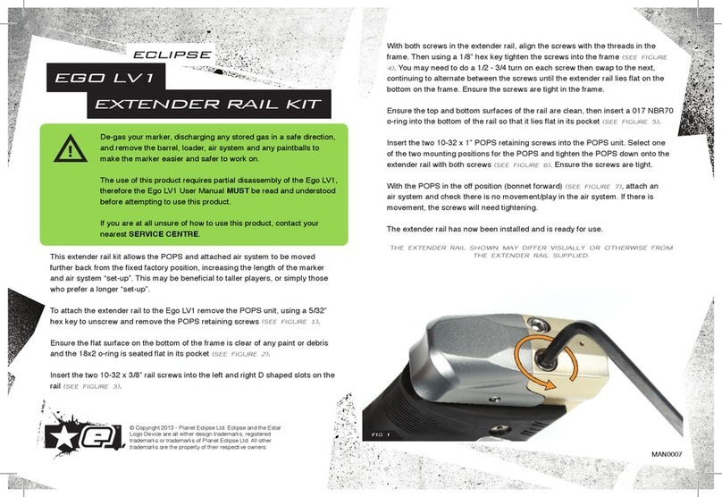
Setting the trigger pull: The Independence features a Critical Paintball
designed trigger. Adjusting the setscrews breaks the Locktite seal and the
setscrews have to be loctited again.
There are four adjustments. Two are adjusted on the front
of the trigger. The trigger contact point is the top set
screw. Turning the screw clockwise makes the contact
point sooner, counterclockwise to make the contact later.
The bottom screw limits the
trigger’s travel backward,
clockwise for less travel,
counter-clockwise for more
travel.
The setscrew to adjust the
trigger return travel can be adjusted by fitting an Allen
wrench through a hole in the trigger lever on the under side of the trigger guard.
Clockwise increases travel – counterclockwise limits travel.
The setscrew that
adjusts the trigger
spring’s tension is
visible when you
remove the bolt,
remove the Ram Cap, and slide the hammer back.
Turning the setscrew clockwise increases tension.
Counter-clockwise lessens the tension. If the tension is
not getting lighter do not continue to turn or you will
screw the setscrew out of the holder. Repeat! If the trigger isn’t getting lighter –
STOP! It is best to start by increasing the tension to get the feel for the spring
and then raise the setscrew until it is at your preference, or it is at the minimum
pressure.
To remove the trigger, loosen the setscrew holding the
trigger pin with an Allen wrench. This must be done with the
body off he trigger frame. Removal of the trigger may cause
the trigger spring to drop out and become lost. It is best to
remove the gun body and ram body completely from the
trigger grip frame. Then remove the trigger spring holder and
the spring before removing the trigger pin.
.
10

Low and High (Inline) Pressure Regulators:
Clockwise (In or Down) lowers the air pressure
Counter Clockwise, (Out or Up) increases the air pressure
LPR
The Low Pressure
Regulator design is a
common one in high-
end paintball markers.
A floating piston (8) is
suspended between two O-Rings (7) and one inside LPR body (10). The floating
piston has a long appendage that both conducts air and holds a seal (9), which
blocks the incoming air. The spring (6) between the piston and the LPR body
pushes the Piston away from the LPR body to allow air to escape through the
LPR body (10). When the pressure between O-Rings 4 and 7 becomes great
enough that pressure overcomes the pressure of the spring (6) the piston seal is
pushed against a seat in the piston body and the airflow stops. A setscrew (1) in
the LPR cap pushes the second piston, the one holding the O-Ring (3) That
piston in turn pushes a lighter spring (5), which rests against the same piston (8)
as the stiffer spring. Screwing down the setscrew (1) increases the pressure on
the lighter spring, which lowers the LPR pressure. The balance between the two
springs plus the pressure of the inside the cap is what regulates (changes) the
operating pressure.
To service your LPR, remove the cap. It should unscrew easily, if it doesn’t there
is pressure in the cap. Purge the gun. Once the cap is removed, the “T” shaped
piston can slide out. Once the piston is removed the top spring easily falls out.
You can take the setscrew out of the cap and then press out the piston (3) and
re-grease that O-Ring (4). There is an additional O-Ring LPR housing that seals
on the piston (3). It can be removed and can be re-greased. Both are a number
010 O-ring and can be seen by looking into the LPR body once the piston has
been removed. The only service usually necessary is to re-lube the O-Rings. In
the event that you have LPR creep that is not fixed by lubing the O-Rings or
replacing the O-Rings then the 3/16th’s seal at the bottom of the “T” piston (9)
should be removed and replaced.
LPR creep is only possible if air is escaping past seal in the bottom of the “T”
piston. Air leaking past the piston O-Ring (5) will have an audible leak from the
surface between the LPR cap and the Front gun body. The same air leak is
heard if you remove the LPR body and find damage on the 018 O-rings sealing
the LPR body. Bad O-Ring seating on the cap piston (8) causes air to leak
between the LPR cap and the front setscrew.
11

Alien Air Force
Inline Regulator (high pressure):
Clockwise (In or Down) lowers the air pressure
Counterclockwise out or up increases the air pressure
Notable is how few parts there are on
the ‘new for ’09’ Inline Regulator.
Cap, Base, Piston and Adjuster, plus
Bellville washer springs.
The regulator top holds a single Bellville
washer spring, the larger disk. This
spring needs to have the dome facing
the Piston. On the piston stem are six
more spring disks.
The base holds the high-pressure air inlet
(the adjuster) a ball bearing, a setscrew and
a stainless steel disk. Raising and lowering
the adjuster changes the pressure. A
setscrew and a ball bearing move the
adjuster. Below the ball bearing a stainless
steel disk reduces wear. At the top of the
base is a 012 O-Ring that seals on the
Piston stem.
In the unlikely event air leaks out the setscrew hole in the base,
the adjuster can be removed and the two 010 O-Rings can be
replaced, by first removing the setscrew and then pushing up the
ball bearing and adjuster. The adjuster is threaded inside to allow
the screw that holds the trigger frame and body together to be
screwed into the adjuster, so that the adjuster can be pulled out of
the base. Do not allow the ball bearing or the disk to fall out of the
base. However the adjuster and O-Rings move so little that
deterioration over its useful life is so minimal that servicing the
adjusting should be unnecessary.
Servicing of the inline regulator should be limited to annual or semi annual
lubricating of the O-Ring on the piston and the O-Ring at the top of the base. The
seal is easily removed and can be replaced. Replacing the seal, the two O-Rings
on the adjuster, the O-Ring on the piston and the O-Ring in the base, completely
rebuilds the ‘Alien Air Force’ Inline Regulator.
12

Assembly and Disassembly:
It is best NOT to take the board out of the marker as the on/off pin and the board
pins are easily lost. Also the wires can be easily broken. If the board is removed
it is best to replace the top board pin first, then put the board in place and then
slide the bottom pin in place.
To access the wires you should take off the left panel. This allows the wires to be
lowered when disassembling and assembling the gun.
To access the tournament lock it is easier to remove the right panel. There are
four toggle switches; the first three should be down. To enable programming
Number four should be up. To lock the gun put all four switches down.
Remember it’s the switch furthest away. The gun is factory set in “Normal” mode;
the tournament lock is not on.
The Independence can be pulled into its three
main pieces, powered up, aired up and the ram
operated. This ability makes Independence
exceptionally easy to trouble shoot. Problems
are found quickly and easily, and are just as
easy to fix.
Disassembly:
To disassemble remove the bolt, take the grip panel off the left side of the gun
(barrel facing away from you) and remove the
wires to the eyes and the solenoid and
straighten them out. Next, remove the two
screws on the underside of the gun, one
under the trigger guard and one at the back.
Then slide the trigger frame and the gun body
apart while feeding the wire up through the
trigger frame until the Trigger Frame is
completely separated from the Body and
Ram.
The marker components are visible. The valve pin assembly is easily viewed, as
is the hose and the hose fittings. Hose fitting are quick release type. To remove
the ram – without pressure in the hose – push the fitting
release toward the fitting body, pull on the ram body; the hose
will easily slide out of the fitting.
Pressing on the valve pin with an Allen Wrench should easily
open it.
13

With the setscrew to the Cup Seal Valve in place you can see that the threads
holding the setscrew are missing on the sides. This is
because of the oval cut made to match the cut in the top of
the cup seal for the Sweep airflow.
You can install the longer LPR hose supplied with the gun
to gas up the marker while the ram is separated from the
gun body to check for the source of any leak.
To remove the Cup Seal Valve assemble, first check to make sure the guns is
not holding pressure, then remove the setscrew and, with needle-nose pliers, pull
the cup seal assembly out of the gun body. However the Cup Seal should only
be removed because you have a leak down the barrel.
The front edges of cup seal valves are prone to
damage. Alien’s valve body has raised edges to
protect the seat if the valve body is dropped or
hit against another surface.
Look for a foreign substance on the body or the
cup seal cap. This can be caused from dirty air in
a compressor. Next, make sure the O-Rings do
not have any nicks. Then check the raised ridge
on the Cup Seal with your fingernail. If you can feel a bump or catch, that is
where it is leaking. A small nick can cause a leak and once it is nicked it is likely
that you will have to replace the Valve body.
Oil the O-Rings before replacing the Cup Seal
assembly and put the pin on the spring before
sliding the cup seal back into the body. Don’t force
the Cup Seal as the O-Rings can be cut when
replacing the valve in the body.
MAKE SURE the open end faces inside the body!
The cap sits against the ridge. If your gun no
longer shoots, but still cycles, turn the cup seal around!
As previously mentioned, there is little reason to take the LPR body out of the
body. In the event of a leak down the
barrel, removing the ram and taking the
cup seal out the back is usually the best
way to service. To remove the LPR detach
the Inline Regulator. One screw holds the
LPR body to gun body.
14

Reassembly: Trigger fame should be assembled with the
right side panel on, left panel off. Trigger and
spring stop in place; trigger spring tension
set, trigger travel set, setscrews loctited. The
On/Off pin is in place and the board pins are
seated. To make sure the trigger wires are
not broken, turn the board on and pull the
trigger. Because the eye harness is not
connected the LED should be green or blue.
Pulling the trigger should change the LED
color, as the eyes do not see ball dropping
down and being fired.
Gun body should be assembled. The cup seal valve’s setscrew is tightened.
Valve pin should open with light pressure. Ball detents are in place. The LPR
inspected to see that both springs are in place and the LPR’s piston is lubed on
both ends with the seat in place.
Inspect Ram to see that the cap in on and the screws holding down the solenoid
are tight. The screws are small however and most anyone can strip the body with
too much force. Snug and locktited!
Slide the ram into the gun body while sliding
the hose into the fitting. The gun now
consists of two half’s: the gun body with the
ram, and the Trigger frame.
Feed the eye wires and the solenoid wire into
the trigger frame – but do not connect them to
the board. Align the body over the trigger
frame, looking at the screw holes in the gun
body and the trigger frame the trigger frame
should be about a half inch forward of
alignment to the gun body. Notice the
channel cut between the side of the trigger
frame and trigger. One side has the trigger
spring stop; one side has a channel to hold the eye wires.
Reach in with an Allen wrench and push the eye
wires into the groove in the trigger frame. The
wires do not have to go fully into the groove as
there is also a groove cut into the gun body for the
wires. Pushing them into the trigger frame groove
holds the wires so they do not get cut.
15

Do not pull to tightly on the eye wire when you tuck them into the groove in the
trigger frame as this can pull the wires down inside the eye covers and misalign
the eyes. This is also why you have aligned the trigger frame about a half and
inch forward in relationship to the gun body,
While looking at both side of the gun, and pulling the solenoid wires and the eye
wires into the trigger frame slide the two half’s together. The two fit snugly
without force. Once you are satisfied that that the eye wire is not being pulled
between the eye covers and the trigger frame’s wire guide groove, that all excess
eye wire between the guide and the frame is pulled into the trigger frame and the
excess wire to the solenoid is pulled into the frame – double checking to see that
the solenoid wire is not sandwiched between the to gun half’s - screw the gun
together with the two screws, one under the trigger guard and one at the back of
the gun under the ram. DO NOT OVER TIGHTEN.
Connect the wire leads to the board and screw the grip panel on.
16

Software Section:
1
1.
.
T
Tu
ur
rn
ni
in
ng
g
O
ON
N
a
an
nd
d
O
OF
FF
F
Press the Power Button, the LED lights up and marker is ON. Press and hold till LED flashes
white and release, marker is off.
1
1.
.1
1.
.
F
Fo
or
rc
ce
ed
d
S
Sh
ho
ot
t
Hold the trigger back for 1 second and the marker fires once, even when there is no ball in the
breach. This clears a ball that has rolled past the eye or starts a sound activated hopper.
Caution! Forced Shot is active if the marker has a ball in the breach or not! Whenever the trigger
is pulled and held for 1 second the marker will fire one shot. A ball that has rolled past the eyes or
a ball(s) in the barrel will fire. Broken paint, broken shell or other objects in the gun or beach will
be fired.
1
1.
.2
2
E
Ey
ye
es
s
O
ON
N
/
/O
Of
ff
f
Marker powers on with eyes on, to turn eyes off quickly press Power button.
1
1.
.3
3
E
Ey
ye
e
E
Er
rr
ro
or
r
In the event of eye malfunction the marker turns the eyes off automatically and the LED changes
color. When the eyes function normally the eyes turn back on and the LED color changes
1
1.
.4
4
L
LE
ED
D
D
Di
is
sp
pl
la
ay
y Color Chart
Green Ball in breach - Semi-Auto mode Will Fire
Blue Ball in breach – Ramping Fire modes Will Fire
Red Ball not in breach - normal modes Will Not fire (Forced shot fires)
Purple Eyes off Will Fire
Yellow Eye error Will Fire
White Ball not in breach - Demonstration mode Will Fire
Teal Ball not in breach - Training mode Will Fire
Red Ball in breach - Demo / Training modes Will Not Fire.
2
2.
.
B
Ba
at
tt
te
er
ry
y
S
St
ta
at
tu
us
s
I
In
nd
di
ic
ca
at
to
or
r
The battery level is checked when marker is powered on.
Battery level LED display Action
More than 60% Nothing Directly in firing mode
Between 40% and 60% Blinking RED Blinking RED for 3 seconds. Then goes into firing
mode. Solenoid will “probably” cycle,
Inconsistant velocity.
Between 20% and 40% 2 Flash RED 2 Flash RED for 3 seconds. Then goes into firing
mode. Solenoid usually will not cycle.
Less than 20% RED strobe RED strobe for 3 seconds, then automatically
turn off
A trigger pull bypasses battery check and marker is in firing mode.
In the event your gun stops cycling always change the battery with a fresh high quality battery.
3
3.
.
T
To
ou
ur
rn
na
am
me
en
nt
t
L
Lo
oc
ck
k
S
Sw
wi
it
tc
ch
h
SW4 is the tournament lock switch. First 3 switches are down.
N
No
or
rm
ma
al
l
m
mo
od
de
e.
.Fourth switch is up. Allows changes to settings and operation modes. Tourna
T
To
ou
ur
rn
na
am
me
en
nt
t
L
Lo
oc
ck
k:
:Fourth switch is down. Software changes are not possible. The LED blinks
OFF every 2 seconds to show the tournament lock.
17

4
4.
.
‘
‘D
De
em
mo
on
ns
st
tr
ra
at
ti
io
on
n’
’
a
an
nd
d
‘
‘T
Tr
ra
ai
in
ni
in
ng
g’
’
M
Mo
od
de
es
s
Tournament Lock is off
Hold trigger back and press Power button - continue holding the trigger until the LED is
flashing WHITE, release trigger. The LED is WHITE, marker is in Demonstration Mode
Quickly pressing the Power Button toggles between Training mode (teal) and
Demonstration (White)
Caution! This mode is used with air. Marker fully cycles at the MROF EYE ON rate of fire. The
marker will not fire in Demonstration mode if there is a ball in the breach, but if there is a ball in
the barrel it will fire that Ball! Always handle the marker as if it is loaded
4
4.
.1
1
D
De
em
mo
on
ns
st
tr
ra
at
ti
io
on
n
F
Fe
ea
at
tu
ur
re
e
White LED - to test different firing modes and check the marker’s speed. Uses the last firing mode
stored. Because no ball is fired, air escapes quickly and air is quickly consumed.
The Eye On ROF cap limits the trigger pull. If the MROF is set to unlimited the MROF is limited to
50 BPS, below 30 is the useful maximum.
4
4.
.2
2
T
Tr
ra
ai
in
ni
in
ng
g
F
Fe
ea
at
tu
ur
re
e
TEAL LED - Demonstration mode, but the Dwell is reduced to half. Allows practice firing the
marker without it fully cycling. It uses less air and isn’t as loud.
5
5.
.
F
Fi
ir
ri
in
ng
g
m
mo
od
de
es
s
Five (5) basic modes can be used with the other settings to generate all tournament legal firing
modes. To change firing modes see the “Programming Mode” section.
Every firing mode is affected by the MROF (Maximum Rate Of Fire) setting.
1 Semi-Auto Fire
The marker fires one ball per trigger pull. Trigger Memory and BWT (Ball Wait Time) settings are
active.
2 Ramping Fire
When the trigger pull rate reaches the Ramp Activation level point the Ramp Scale adds
extra shots at the selected rate. The ROF limit is the MROF setting.
If the pull rate drops below the Ramp Activation level, ramping stops.
The Safety Shots apply if the time between the trigger pulls is longer than the Ramp Time
Out setting.
Trigger Memory and BWT settings are active.
3 Burst Fire
Each trigger pull fires the number of balls in the Ramp Scale setting.
Maximum Rate of Fire is capped at the MROF setting.
4 Full Auto Fire
Continuous fire when trigger is held down.
Maximum Rate of Fire is capped at the MROF setting.
5 Response Fire
Fires when trigger is pulled and when released.
Trigger Memory and BWT settings are active.
18

6
6.
.
Q
Qu
ui
ic
ck
k
S
St
ta
ar
rt
t
M
Mo
od
de
es
s
The Quick Start Modes are packets of setting for tournaments or that are popular
Tournament Lock is off.
Hold trigger press Power Button - continue holding the trigger back until the LED flashes
YELLOW. Release the trigger. LED is RED.
Cycle through choices by pulling the trigger.
To select a mode, hold the trigger for 3 seconds The LED flashes multiple colors.
Release the trigger. After 3 seconds the marker shuts off automatically. Next time the
marker will turn on in the selected mode.
LED Color Quick Start Mode
Solid RED Millennium/Centurio Mode
Solid GREEN PSP Mode
Solid BLUE NXL Mode
Solid YELLOW NPPL Mode
Solid PURPLE Response Mode
Blinking RED Full Auto Mode
Blinking GREEN Semi-Auto Mode
Blinking BLUE Burst Uncapped ( PSP Uncapped)
Blinking YELLOW Reset to factory defaults
Warning: Changing these settings will change several settings at once on the marker. Resetting
to factory defaults will reset all the parameters to the factory default, including the Dwell.
6
6.
.1
1
S
Se
et
tt
ti
in
ng
gs
s
f
fo
or
r
e
ea
ac
ch
h
Q
Qu
ui
ic
ck
k
S
St
ta
ar
rt
t
M
Mo
od
de
e
Quick Start Modes will change each of the following settings listed below. Individual settings can
be adjusted afterward.
Millennium/Centurio settings
Max ROF Eyes On 15 15 bps
Max ROF Eyes Off 15 15 bps
Fire Mode 2 Ramping
Safety shots 1 1 shot
Ramp activation 15 7.5 trigger pulls a sec (133.3ms)
Ramp time out 9 Ramp activation time (133.3ms)
Trigger memory 2 2 balls
BIP wait time 2 100 ms
Ramp scale level 2 2 shots
PSP settings
Max ROF Eyes On 15 15 bps
Max ROF Eyes Off 15 15 bps
FireMode 3 Burst
Safety shots 3 3 shots
Ramp time out 1 1 sec
Trigger memory 3 3 balls
BIP wait time 5 250 ms
Ramp scale level 3 3 shots
19

NXL settings
Max ROF Eyes On 15 15 bps
Max ROF Eyes Off 15 15 bps
FireMode 4 FullAuto
Safety shots 3 3 shots
Ramp time out 1 1 sec
NPPL settings
Max ROF Eyes On 1 Uncapped
Max ROF Eyes Off 20 20 bps
FireMode 1 Semi-Auto
Trigger memory 1 1 ball
BIP wait time 2 100 ms
Response settings
Max ROF Eyes On 20 20 bps
Fire Mode 5 Response
Safety shots 1 1 shot
Ramp time out 1 1 sec
Trigger memory 3 3 ball
BIP wait time 3 250 ms
Full Auto settings
Max ROF Eyes On 25 25 bps
FireMode 4 FullAuto
Safety shots 10 10 shots
Ramp time out 1 1 sec
Semi-Auto settings
Max ROF Eyes On 20 20 bps
FireMode 1 Semi-Auto
Trigger memory 1 1 ball
BIP wait time 5 250 ms
Burst Uncapped settings
Max ROF Eyes On 1 Uncapped
FireMode 3 Burst
Safety shots 3 3 shots
Ramp time out 1 1 sec
Trigger memory 5 5 balls
BIP wait time 5 250 ms
Ramp scale level 5 5 shots
20
Table of contents