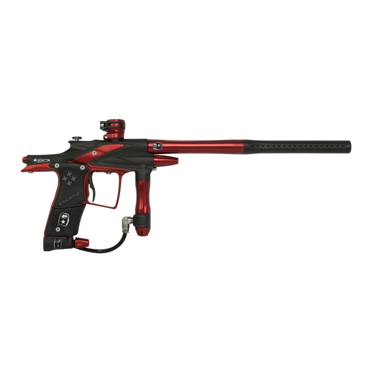
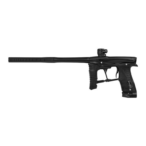
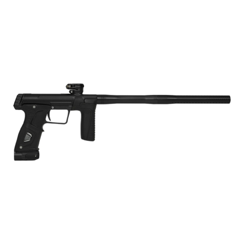
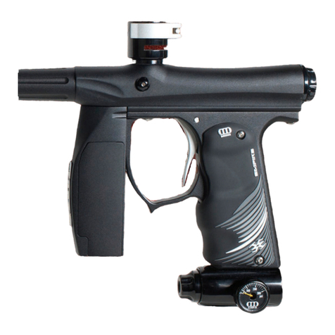
Eclipse ETEK 5 User manual

USER MANUAL: ENGLISH EDITION

2 ETEK5 MANUAL
• Please read and understand all instruction manuals before use.
• The Eclipse ETEK5 is not a toy. PAINTBALL SAFETY RULES MUST BE
FOLLOWED AT ALL TIMES.
• Careless or improper use, including failure to follow instructions and
warnings within this User Manual and attached to the ETEK5 could cause
death or serious injury.
• Do not remove or deface any warnings attached to the ETEK5.
• Paintball industry standard eye/face/ear and head protection designed
specically to stop paintballs and meeting ASTM standard F1776 (USA)
or CE standard (Europe) must be worn by the user and any person within
range. Proper protection must be worn during assembly, cleaning and
maintenance.
• Hearing protection should be worn.
• Never shoot at a person who is not wearing proper protection.
• Never look directly into the barrel of the marker. Accidental discharge into
the eyes may cause permanent injury or death. Never look into the barrel or
breech area of the ETEK5 whilst the marker is switched on and able to re.
• Keep the ETEK5 switched off until ready to shoot.
• Treat every marker as if it is loaded and ready to re.
• The electronic on/off button is the marker’s disabling device, also known as
a safety, which prevents the marker from ring. Always switch off the marker
when not in use.
• Always t a barrel-blocking device to the ETEK5 when not in use.
• Always remove all paintballs from the ETEK5 when not in use on the eld
of play.
• Never point the ETEK5 at anything you do not intend to shoot.
• Do not shoot at persons within close range.
• Do not eld strip or remove any parts while the marker is pressurised.
• Do not pressurise the ETEK5 without all the components of the marker
correctly installed, as high-pressure gas may be emitted.
• Do not re the ETEK5 without the bolt correctly installed.
• Never put your nger or any foreign objects into the paintball feed tube of
the ETEK5.
• Never allow pressurised gas to come into contact with any part of your body.
• Always remove the rst stage regulator and relieve all residual gas pressure
from the ETEK5 before disassembly.
• Always remove the rst stage regulator and relieve all residual gas pressure
from the ETEK5 for transport and storage.
• Always follow guidelines given with your rst stage regulator for safe
transportation and storage.
• Always store the ETEK5 in a secure place.
• Persons under 18 years of age must have adult supervision when using or
handling the ETEK5.
• Observe all local and national laws, regulations and guidelines.
ADHERE STRICTLY TO THESE AND ALL OTHER
SAFETY INSTRUCTIONS AND GUIDELINES!
WARNING!
WARNING

ETEK5 MANUAL 3
ADHERE STRICTLY TO THESE AND ALL OTHER
SAFETY INSTRUCTIONS AND GUIDELINES!
WARNING!
• Use only professional paintball elds where codes of safety are
strictly enforced.
• Use compressed air/nitrogen only. Do not use any other compressed gas or
pressurised liquid including CO2.
• Always follow instructions, warnings and guidelines given with any rst stage
regulator you use with the ETEK5.
• Use 0.68 inch calibre paintballs only.
• Always measure your marker’s velocity before playing paintball, using a
suitable chronograph.
• Never shoot at velocities in excess of 300 feet (91.44 meters) per second, or
at velocities greater than local or national laws allow.
• Any installations, modications or repairs should be carried out by a
qualied individual at a licensed and insured paintball facility.
This Users Manual is in English.
It contains important safety guidelines and
instructions. Should you be unsure at any stage,or
unable to understand the contents of this manual
you must seek expert advice.
Le mode d’emploi est en Anglais.
Il contient des instructions et mesures de sécurité
importantes. En cas de doute, ou s’il vous est
impossible de comprendre le contenu du monde
d’emploi, demandez conseil à un expert.
Este manual de usuarios (operarios)
Usarios está en Inglés.Contiene importantes
normas de seguridad e instrucciones. Si no está
seguro de algùn punto o no entiende los contenidos
de este manual debe consultar con un experto.
Diese Bedienungs - und Benutzeranleitung ist
in Englisch.
Sie enthålt wichtige Sicherheitsrichtlinen und -
bestimmungen. Solten Sie sich in irgendeiner Weise
unsicher sein, oder den Inhalte dies Heftes nicht
verstehen, lassen Sie sich bitte von einen Experten
beraten.
THIS USER MANUAL MUST ACCOMPANY THE PRODUCT IN THE
EVENT OF RESALE OR NEW OWNERSHIP. SHOULD YOU BE
UNSURE AT ANY STAGE YOU MUST SEEK EXPERT ADVICE
(SEE SERVICE CENTRES PAGE 62).
WARNING

CONTENTS
4 ETEK5 MANUAL
USING THE ETEK5
Details on how to get up and running quickly with your ETEK5.
This section is essential reading for everyone.
6 Factory set-up guide
7 Installing a 9v battery
8Switching on the ETEK5
Switching off the ETEK5
Firing the ETEK5
9 Switching on the ETEK5 with OLED board tted
Switching off the ETEK5 with OLED board tted
Firing the ETEK5 with OLED board tted
10 The ETEK5 circuit board
11 The ETEK5 OLED board
12 Using the Breech Sensor
13 Using the Breech Sensor with OLED board tted
14 The ETEK5 navigation console
15 Setting up the ETEK5
Installing a barrel
16 Straight macroline ttings
Macroline hosing
17 Installing a preset air system
19 Attaching a loader
20 Setting the trigger
21 Adjusting the velocity
Adjusting the LPR pressure
22 Unloading the ETEK5
23 Storage and transportation
24 The tournament lock
25 Understanding the Breech Sensor operation
The battery level indicator
ADVANCED SET-UP
In depth information on setting up the ETEK5.
26 The SET-UP mode
Modifying a parameter
27 SET-UP parameters
The PRESET parameter
Maximum ROF with Breech Sensor on (capped modes)
Maximum ROF with Breech Sensor off
28 DWELL - Controls the amount of gas that is released with each shot
DEBOUNCE - Adjusts the amount of trigger bounce
THE FACTORY RESET - Resets all settings back to factory standard
ETEK5 OLED BOARD
In depth information covering all aspects of the ETEK5 OLED Circuit Board.
29 Installing the ETEK5 OLED board
30 ETEK5 OLED board navigation console
31 Switching on
Run screen layout
32 The Breech Sensor indicator
The lock indicator
The battery level indicator
33 The SETUP mode
34 PRESET - Selection of compliant preset ring modes
BS ON ROF - Maximum rate of re with Breech Sensor on
BS OFF ROF - Maximum rate of re with Breech Sensor off
35 KICK IN - Rate that the trigger must be pulled per second to begin ramping
RESTART - Time in seconds that ramping can restart after each trigger pull
DWELL - Solenoid energise time in milliseconds
DEBOUNCE - Trigger anti-bounce settings
36 SLEEP - Auto power off time in minutes
DISPLAY - Denes what information is displayed on the run screen
ZERO - Allows user to set the display variables to zero

ETEK5 MANUAL 5
MAINTENANCE
A guide to performing routine maintenance on your ETEK5.
37 Cleaning the Breech Sensor (BS)
39 The SL4 inline regulator assembly
41 Advanced SL4 inline regulator maintenance
42 Cleaning the low pressure regulator
44 Cleaning and lubricating the bolt
45 Maintaining the rammer
47 Removing and attaching the frame
49 The ETEK5 trigger assembly
51 The ETEK5 solenoid assembly
53 Maintaining the valve assembly
56 The ETEK5 On/Off Purge System (OOPS)
FAULT FINDING
How to resolve any problems that may arise with your ETEK5.
58 Tables containing symptoms, possible causes and solutions
SERVICE CENTRES
Information on the location of your nearest ETEK5 Service Centre.
62 Planet Eclipse Service Centres
TECHNICAL RESOURCES
Essential illustrated diagrams and component lists for the ETEK5.
63 Operational overview
64 Parts lists
66 The Shaft4 barrel
67 SL4 inline regulator
68 ETEK5 bolt assembly
Zick3 rammer assembly
69 ETEK5 solenoid assembly
70 The On/Off Purge System (OOPS)
71 Trigger assembly
Clamping feed tube assembly
72 ETEK5 board
ETEK5 board with OLED board tted
73 Common o-ring size chart
74 Common screw size chart
75 ETEK5 OLED board parameter overview
WARRANTY CARD
Tear-out product registration card to be completed and returned.
Alternatively register online at www.planeteclipse.com
INDEX
NOTES

WARNING!
De-gas your marker, discharging any stored gas in a safe direction, and
remove the barrel, loader, air system and any paintballs to make the marker
easier and safer to work on.
WARNING
USING THE ETEK
6 ETEK5 MANUAL
FACTORY SET-UP GUIDE
Before using the ETEK5 it is important to make sure that the inline regulator, low
pressure regulator and all electronically controlled parameters are set correctly,
as some of these may have a negative (and potentially damaging) effect on the
marker (in terms of performance and reliability), if incorrectly set.
The steps below will restore the ETEK5 to the state that it left the factory.
Reset the control parameters to the factory settings (see page 28).
Check the inline regulator adjuster screw is set to 4 turns clockwise from its
maximum output (counter-clockwise) position (see gure 1A). This will ensure the
inline regulator is set to an output pressure that will not damage the ETEK5 when
supplied with compressed air/nitrogen (see page 21 for more information on the
inline regulator).
Check the low pressure regulator adjuster screw is set to one turn anti-clockwise
from its fully inwards position (see gure 1B) (see page 21 for more information
on the low pressure regulator).
How to get up and running
quickly with your ETEK5.
FIG 1A
FIG 1B
+
+
_
_

USING THE ETEK5
ETEK5 MANUAL 7
INSTALLING A 9V BATTERY
Ensure that the ETEK5 is switched off. Place the marker on a at surface in
front of you with the feed tube furthest away from you and the barrel pointing
to the right.
Using a 5/64” (2mm) hex key, remove the two countersunk screws that hold the
rubber grip onto the right side of the grip frame (see gure 2A). Peel the rubber
grip to the right to expose the battery within the grip frame.
If present, remove the existing 9 volt battery by sliding your thumb or nger into
the recess provided at the bottom of the battery and lever the battery gently out
of the frame (see gure 2B).
Connect a new 9 volt Alkaline battery (type PP3, 6LR61, 1604A)1to the battery
connector (see gure 2C).
Fit the battery upside down inside the ETEK5 frame, with the battery connector at
the bottom. If you are unsure of how to install a new battery please contact your
nearest Eclipse Service Centre.
Ensure that the battery wire is tucked into the recess within the frame as pictured
(see gure 2D), then replace the rubber grip and tighten the countersunk grip
screws using the 5/64” (2mm) hex key.
DO NOT OVER-TIGHTEN THE SCREWS.
1 Do not use rechargeable batteries or low quality batteries.
FIG 2A
FIG 2B
FIG 2C
FIG 2D

SWITCHING ON THE ETEK5
At the rear of the frame is the navigation console which houses the Select button
(labelled A gure 3A). This button is the disabling device for the ETEK5,
used to switch the marker on and off. Press and hold the Select button .
Release the Select button when the LED lights up and your ETEK5 will begin
its power up sequence.1,2
SWITCHING OFF THE ETEK5
Press and hold the Select button . Release the Select button when the LED
on the navigation console turns red.
FIRING THE ETEK5
If the Breech Sensor (BS) is disabled, pull the trigger to re the ETEK5. If
the Breech Sensor is enabled and there is a paintball in the breech, pulling
the trigger will also re the ETEK5. The entire ring sequence is controlled
electronically by the ETEK5 circuit board and solenoid, enabling any user to
achieve high rates of re easily.
1 When the ETEK5 is turned on, the Breech Sensor is automatically enabled.
2 The colours displayed during the power up sequence may vary depending on the region the
marker was originally purchased.
USING THE ETEK5
8 ETEK5 MANUAL
FIG 3A
A

USING THE ETEK5
ETEK5 MANUAL 9
SWITCHING ON THE ETEK5 WITH OLED BOARD FITTED
At the rear of the frame is the navigation console which houses the Select button
(labelled A gure 4A). This button is the disabling device for the ETEK5, used to switch
the marker on and off. Press and hold the button until the ETEK5 OLED board begins
its power up sequence.1,2
SWITCHING OFF THE ETEK5 WITH OLED BOARD FITTED
Press and hold the button until the display shows GOODBYE. Release the button.
FIRING THE ETEK5 WITH OLED BOARD FITTED
If the Breech Sensor (BS) is disabled, pull the trigger to re the ETEK5. If the Breech
Sensor is enabled and there is a paintball in the breech, pulling the trigger will also re
the ETEK5. The entire ring sequence is controlled electronically by the ETEK5 board and
solenoid, enabling any user to achieve high rates of re easily.
1 When the ETEK5 is turned on, the Breech Sensor is automatically enabled.
2 By continuing holding down the button when turning on the ETEK5 OLED board the software
version number will be displayed.
FIG 4A
A

THE ETEK5 CIRCUIT BOARD
The ETEK5 circuit board sits within the frame and is accessible by removing the
rubber grips (see page 29 to learn more).
There are three sockets on the ETEK5 circuit board (see gure 5A), the ETEK5
solenoid connector A, the BS connector Band the micro-switch connector C .
There is also a tournament lock button Dand the OLED board connector E.
Information on the tournament lock button functionality can be found on page 24.
1 When the ETEK5 is turned on, the Breech Sensor is automatically enabled.
2 The colours displayed during the power up sequence may vary depending on the region the marker
was originally purchased.
USING THE ETEK5
10 ETEK5 MANUAL
FIG 5A
A
B
C
D
E

USING THE ETEK5
THE ETEK5 OLED BOARD
The ETEK5 OLED board connects to the existing ETEK5 circuit board, which sits
within the frame and is accessible by removing the rubber grips (see page 29 to
learn more).
There are three sockets on the ETEK5 circuit board (see gure 6A), the ETEK5
solenoid connector A, the BS connector Band the micro-switch connector C .
There is also a tournament lock button D.
Information on the tournament lock button functionality can be found on page 24.
The OLED board (labelled F gure 6A) attaches to the standard ETEK5 board via
the connector at the bottom of the ETEK5 circuit board (labelled E gure 6A).
The mating connector sits to the upper left of the OLED board, which sits inline with
the ETEK5 circuit board and extends downwards.
Before installation into your ETEK5 frame make sure you gently remove the OLED
display’s protective lm using the green tab (labelled G gure 6A).
For further details of how to install the OLED board see page 29.
1 When the ETEK5 is turned on, the Breech Sensor is automatically enabled.
2 By continuing holding down the button when turning on the ETEK5 OLED board the software
version number will be displayed.
ETEK5 MANUAL 11
FIG 6A
A
B
C
D
E
F
G

USING THE ETEK5
12 ETEK5 MANUAL
WARNING!
The ETEK5 may still re even if there is no paintball in the breech. Always
ensure all safety guidelines are followed when the ETEK5 is switched on.
WARNING
FIG 7A
A
B
USING THE BREECH SENSOR
The Breech Sensor (BS) is used to detect when a paintball is ready to re from
the ETEK5. If no paintball is ready then the BS will inhibit the ETEK5 from ring.
This prevents the ETEK5 from ‘chopping’ paintballs that are not fully loaded into
the marker.
When the ETEK5 is powered up, the Breech Sensor (BS) is automatically
enabled.
To switch off the Breech Sensor, push and hold the Select button
(labelled B gure 7A) for 0.5 seconds. The LED (labelled A gure 7A) on
the navigation console (see page 14 for more information about the navigation
console) will ash purple indicating that the Breech Sensor has been disabled.
To switch on the Breech Sensor, push and hold the Select button for 0.5
seconds. The LED on the navigation console will ash either yellow (no ball
detected) or light blue (ball detected) indicating that the Breech Sensor has been
enabled.
Additional features of the ETEK5 Breech Sensor are covered in full in the
‘Understanding the Breech Sensor Operation’ section on page 25 of this
User Manual.

USING THE ETEK5
ETEK5 MANUAL 13
WARNING!
The ETEK5 may still re even if there is no paintball in the breech. Always
ensure all safety guidelines are followed when the ETEK5 is switched on.
WARNING
USING THE BREECH SENSOR WITH OLED BOARD FITTED
When the ETEK5 is powered up, the Breech Sensor (BS) is automatically
enabled.
The LED on the navigation console will display the same Breech Sensor
information regardless of the ETEK5 OLED board being installed or not.
To switch off the Breech Sensor, press and hold the Select button on the
navigation console (see page 14 for more information about the navigation
console) for 0.5 second (labelled A gure 8A).
The Breech Sensor indicator on the top right of the OLED display will show
to indicate its ‘Disabled’ status (labelled B gure 8A).
To switch the Breech Sensor to ‘Enabled’, press and hold the button for one
second. The indicator will change back to .
More detailed features of the ETEK5 OLED board’s Breech Sensor are covered in
full on page 32 of this user manual.
FIG 8A
A
B

USING THE ETEK5
14 ETEK5 MANUAL
THE ETEK5 NAVIGATION CONSOLE
The ETEK5 utilises a coloured LED (labelled Agure 9A) to display all of the
information that the user requires.
The console looks slightly different if you have upgraded to the ETEK5 OLED board
(see gure 9B). The LED colour information is further supported by the OLED display
(labelled C gure 9B).
The various functions of both the Select button (labelled Bgure 9A) and the
LED are outlined below.
The select button is used to:
•Switch the ETEK5 on and off.
• Switch the BS (eye system) on and off.
•To scroll through parameters and edit parameters.
The LED on the navigation console is used to:
• Display the status of the BS (eye system).
• Display the value of a parameter.
• Display the status of the battery.
• Display power up and power down status.
• Display tournament lock status.
• Display that factory settings have been restored.
• To conrm whether a parameter value has been accepted or rejected.
Please note: the information displayed on the LED is different when the ETEK5 OLED
board is installed.
STANDARD CONSOLE OLED DISPLAY
FIG 9A FIG 9B
A
B
C
WARNING!
De-gas your marker, discharging any stored gas in a safe
direction, and remove the barrel, loader, air system and any
paintballs to make the marker easier and safer to work on.
WARNING

USING THE ETEK5
ETEK5 MANUAL 15
SETTING UP THE ETEK5
Before you can begin to use your ETEK5, you will need to attach a barrel, an air
system and a paintball loader.
INSTALLING A BARREL
Every ETEK5 comes complete with an Eclipse Shaft4 barrel (see page 66).
To install the Shaft4 barrel, rstly screw the barrel tip and barrel back sections
together. The threads on the Shaft4 barrel tip are reverse threaded, to screw the
two sections together, with the barrel pointing away from you, turn the barrel tip in
a clockwise direction (see gure 10A).
While pointing the ETEK5 marker in a safe direction, insert the assembled Shaft4
barrel into the front of the ETEK5 body and screw the Shaft4 barrel into the
ETEK5 (in a counter-clockwise direction). Continue to screw the Shaft4 barrel into
the ETEK5 body until the barrel becomes tight in the body (see gure 10B).
DO NOT over tighten the barrel.
Install a barrel blocking device over the barrel such as the Eclipse Barrel Sock
supplied with the ETEK51(see gure 10C). You have now installed the barrel.
1 Instruction on using the Eclipse Barrel Sock can be found on the barrel sock warning label.
FIG 10A
FIG 10B
FIG 10C

USING THE ETEK5
16 ETEK5 MANUAL
WARNING!
If the macroline becomes worn, damaged or is the wrong length, replace it
immediately.
Replace the macroline hose with the following grade or higher - 1/4” OD x
1/8”ID Semi Rigid Nylon 11.
If unsure contact your nearest Eclipse Service Centre.
WARNING
STRAIGHT MACROLINE FITTINGS
A straight macroline tting can be found on the inline regulator swivel
(see gure 11A) and the On/Off Purge System (OOPS) (see gure 11B).
These ttings are secured using thread lock and DO NOT need to be removed
during regular maintenance.
MACROLINE HOSING
To aid the longevity of your macroline hosing, it is very important to remove it
from and install it back into the ttings in the correct manner:
Pull back the collet section of the hose tting and keep the collet depressed.
Pull the macroline hose out of the hose tting and release the collet.
Before installing the macroline hose into the tting ensure that the end has been
trimmed correctly and is the correct length to ensure a tight t in the hose tting. FIG 11A
FIG 11B

USING THE ETEK5
ETEK5 MANUAL 17
WARNING!
Make sure the marker is turned off with a barrel blocking device installed
and that no paintballs are in the ETEK5 or loader before installing an air
system.
Compressed air and nitrogen systems can be extremely dangerous if
handled or used incorrectly.
Only use an air system certied for use within the country of use.
The ETEK5 cannot be used with CO2. Only use compressed air or nitrogen.
Never add any lubricants or greases into the ll adaptor of the air system
regulator.
Ensure that all screws are tightened and no parts are loose before installing
an air system.
Do not pressurise the ETEK5 without the bolt system correctly installed, as
high pressure gas will be emitted.
Do not install a compressed air system or load paintballs into the ETEK5
until you feel completely condent with your ability to handle the marker
safely and responsibly.
Always relieve all residual gas pressure from the ETEK5 before unscrewing
the preset air system.
WARNING
INSTALLING A PRESET AIR SYSTEM

USING THE ETEK5
18 ETEK5 MANUAL
INSTALLING A PRESET AIR SYSTEM (CONTINUED)
High, mid and low pressure output preset air systems can be used with the
ETEK5, providing the ETEK5 is tted with the SL4 inline regulator originally
supplied with the marker.
There are two retaining screws on the On/Off Purge System (OOPS) body
underside (see gure 12A). These are used to clamp the OOPS onto the frame.
It is advisable to make sure that these screws are tight using a 5/32” hex key
before attaching an air system.
The Eclipse ETEK5 comes complete with an Eclipse On/Off Purge System
(OOPS) which provides a direct connection for a preset air system. Before
screwing an air system into the OOPS ensure that the OOPS knob is fully
unscrewed (see gure 12B). In this position the OOPS is off and will not
pressurise the ETEK5 when an air system is screwed into the OOPS.
Lining the threads up correctly between the OOPS and the air system, screw the
air system into the OOPS until the air system is screwed all the way in and tight
on the OOPS. The air system MUST be screwed all the way in before turning on
the OOPS (see gure 12C).
Now with the air system attached and the barrel pointing away from you, start
to slowly turn the OOPS knob counter-clockwise to turn the OOPS on and
pressurise the ETEK5. Keep turning the knob until it stops against the OOPS
body as shown in gure 12D.
You have now installed a preset air system onto your ETEK5.
FIG 12D
FIG 12C
FIG 12A FIG 12B

USING THE ETEK5
ETEK5 MANUAL 19
ATTACHING A LOADER
Release the clamping lever on the feed neck (see gure 13A) and test to see
if your loader can easily be pushed into the top of the feed neck. If the loader
cannot easily be pushed into the feed neck, loosen the top screw on the feed
neck by turning it counter-clockwise using a 5/32” hex key (see gure 13B).
When you have managed to push your loader into the feed neck, close the
clamping lever to secure it rmly in place (see gure 13C). If the loader is loose
then you will need to release the clamping lever, tighten the top screw slightly
by turning it clockwise with a 5/32” hex key (see gure 13B), then close the
clamping lever. Repeat this process as necessary to secure your loader in place
You have now attached a loader to your ETEK5. Once you have lled your loader
and air tank you will then be ready to begin using your ETEK5.
WARNING!
Do not over tighten the Clamping Feed Neck as this may damage the
loader or feed neck itself.
WARNING
FIG 13C
FIG 13B
FIG 13A

USING THE ETEK5
20 ETEK5 MANUAL
SETTING THE TRIGGER
There are three adjustment points on the trigger – the pre-travel screw, the post-
travel adjuster screw, and the magnet adjuster screw.
As standard each ETEK5 comes with a factory set trigger travel of approximately
2mm in total length; one millimeter of travel before the ring point and one
millimeter of travel after the ring point.
The pre-travel adjuster screw is used to set the amount of trigger travel prior to
the marker ring. Turn this screw clockwise to reduce the amount of travel. Do not
turn the screw too far or the trigger will be pushed past the ring point and the
marker will not work. Turn this screw counter clockwise to increase the amount of
trigger travel (see gure 14A).
The post-travel adjuster screw is used to set the amount of travel after the marker
has red. Turn this screw clockwise to reduce the amount of travel. Do not turn
the screw too far or the trigger will be prevented from reaching its ring point
and the marker will not work. Turn this screw counter clockwise to increase the
amount of travel (see gure 14B).
The magnet adjuster screw is used to adjust the amount of return force with
which the trigger is returned. Turn the screw clockwise to increase the amount
of magnet return force. Do not turn the screw to far or it will negate the position
of the pre-travel adjuster screw. Turn the screw counter clockwise to reduce the
amount of magnet return force (see gure 14C).
FIG 14C
FIG 14B
FIG 14A
+
+
+
_
_
_
Table of contents
Other Eclipse Paintball Equipment manuals