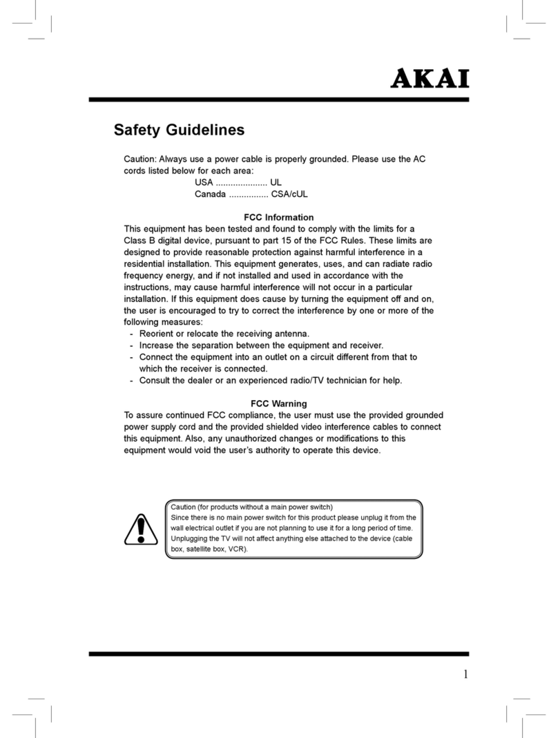
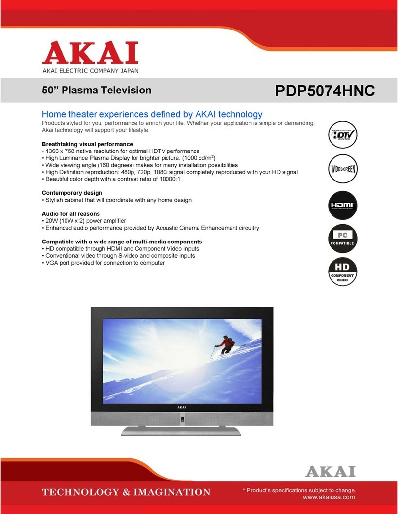
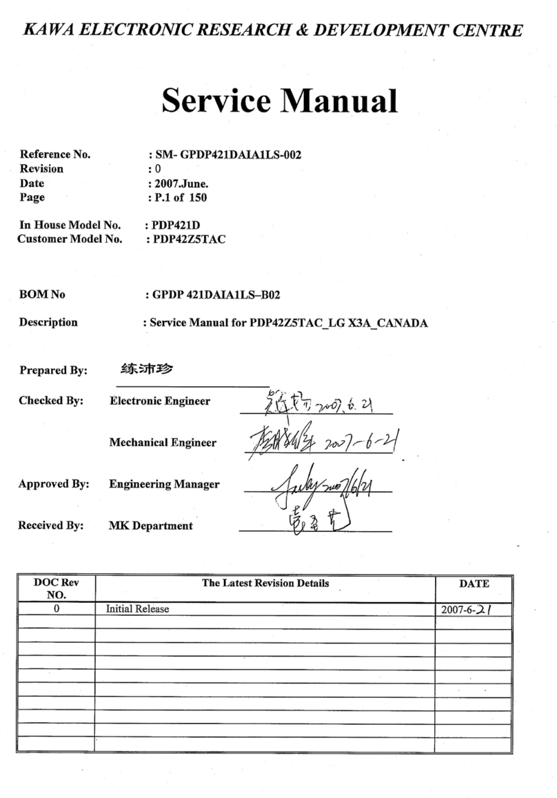
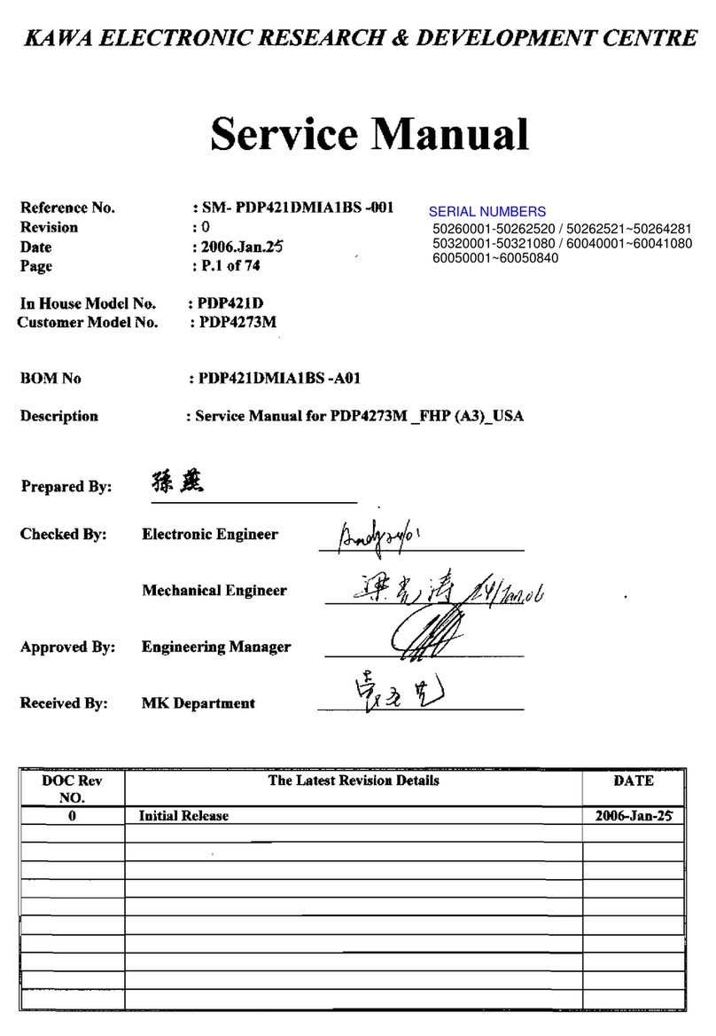
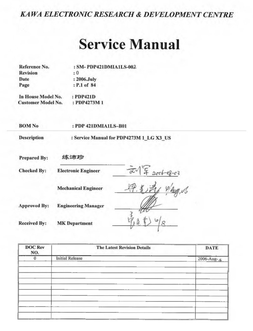
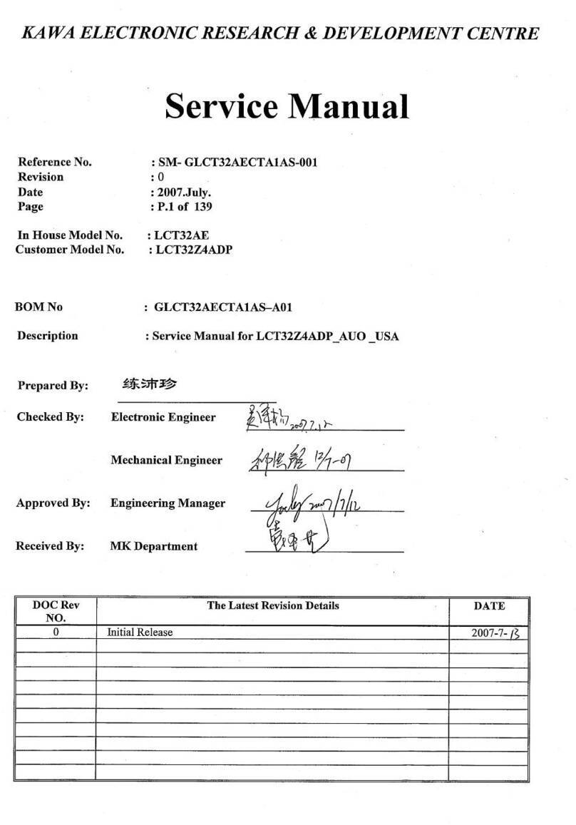
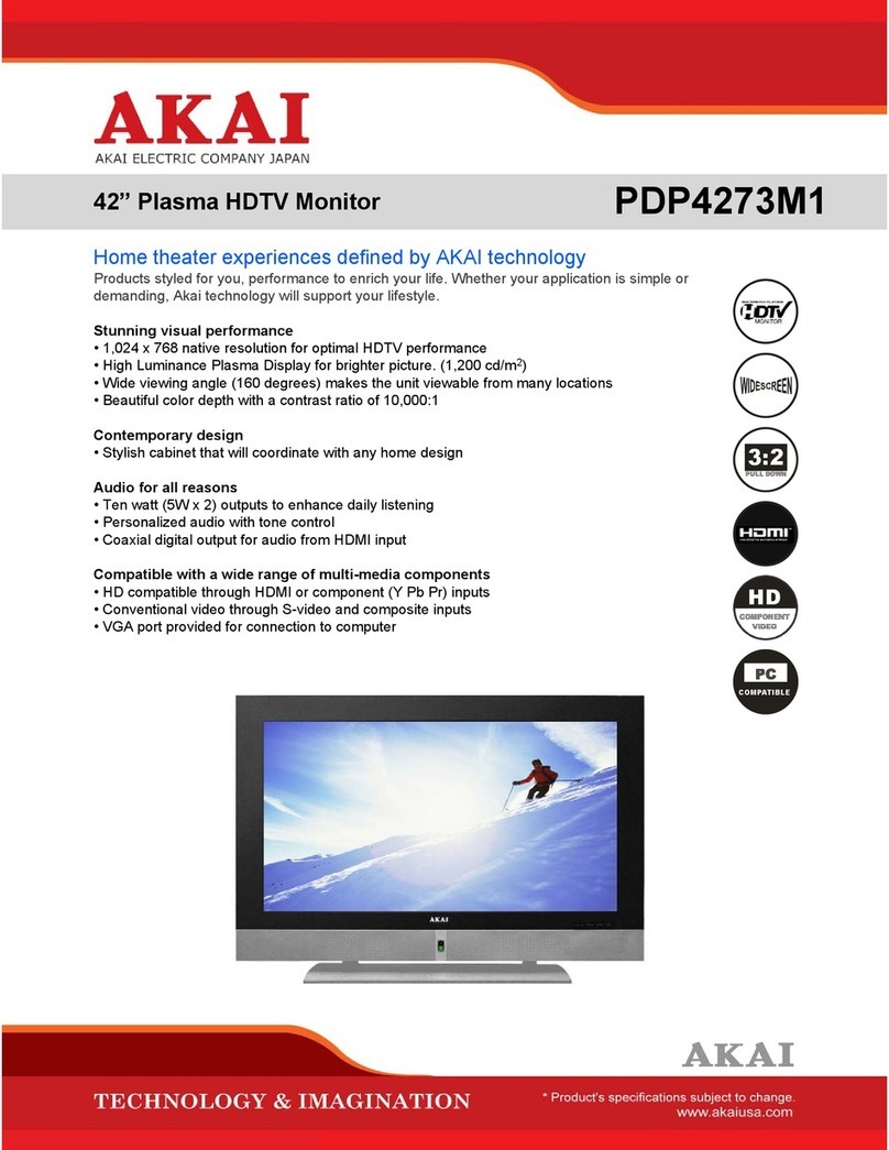
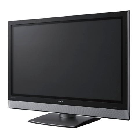
Akai PDP4273M User manual

KA WA ELECTRONIC RESEARCH & DEVELOPMENT CENTRE
S e r v i c e M a n u a l
Reference No.
Revision
Date
Page
In House Model No.
Customer Model No.
BOM No
Description
Prepared B :
Checked B :
Approved B :
Received B :
DOC Rev
NO. The Latest Revision Details DATE
0 Initial Release 2006-Jan-2£
: Service Manual for PDP4273M _FHP (A3)_USA
Electronic Engineer
lechanical Engineer
Engineering Manager
IK Department
SERIAL NUMBERS
50260001-50262520 / 50262521~50264281
50320001-50321080 / 60040001~60041080
60050001~60050840
: PDP421D
: PDP4273M
: PDP421DMIA1BS -A01
SM- PDP421DMIA1BS -001
0
2006.Jan.25
P.l of 74

SERVICE MANUAL
Model:
PDP4273M
Safety Pre aution............................................................................................1-2
Te hni al Spe ifi ations..............................................................................3-10
Blo k Diagram.............................................................................................11-12
Cir uit Diagram...........................................................................................13-28
Basi Operations & Cir uit Des ription
.................................................
29-33
Main IC Spe ifi ations...............................................................................34-54
Panel Information....................................................................................... 55-67
Spare Part list.............................................................................................68-69
Exploded View.................................................................................................70
If You Forget Your V-CHIP Password
........................................................
71
Software Upgrade............................................................................................72
This manual is the latest at the time of printing, and does not
include the modification which may be made after the printing,
by the constant improvement of product.

Safety Precaution
ACAUTION
RISK OF L CTRIC SHOCK
DO NOT OP N
CAUTION: TO R DUC TH RISK OF
L CTRIC SHOCK, DO NOT R MOV COV R
(OR BACK). NO US R-S RVIC ABL PARTS
INSID . R F R S RVICING TO QUALIFI D
S RVIC P RSONN L ONLY.
AThe lightning flash with arrowhead symbol,
within an equilateral triangle, is intended to
alert the user to the presen e of uninsulated
“dangerous voltage” within the produ t’s en lo
sure that may be of suffi ient magnitude to
onstitute a risk of ele tri sho k to persons.
The ex lamation point within an equilateral
triangle is intended to alert the user to the
presen e of important operating and
maintenan e (servi ing) instru tions in the
literature a ompanying the applian e.
PR CAUTIONS DURING
S RVICING
1. In addition to safety, other parts and
assemblies are spe ified for onforman e with
su h regulations as those applying to spurious
radiation. These must also be repla ed only
with spe ified repla ements.
Examples: RF onverters, tuner units, antenna
sele tion swit hes, RF ables, noise-blo king
apa itors, noise-blo king filters, et .
2. Use spe ified internal Wiring. Note espe ially:
1) Wires overed with PVC tubing
2) Double insulated wires
3) High voltage leads
3. Use spe ified insulating materials for hazardous
live parts. Note espe ially:
1) Insulating Tape
2) PVC tubing
3) Spa ers (insulating barriers)
4) Insulating sheets for transistors
5) Plasti s rews for fixing mi ro swit hes
4. When repla ing AC primary side omponents
(transformers, power ords, noise blo king
apa itors, et .), wrap ends of wires se urely
about the terminals before soldering.
5. Make sure that wires do not onta t heat
generating parts (heat sinks, oxide metal film
resistors, fusible resistors, et .)
6. Che k if repla ed wires do not onta t sharply
edged or pointed parts.
7. Make sure that foreign obje ts (s rews, solder
droplets, et .) do not remain inside the set.
MAK YOUR CONTRIBUTION
TO PROT CT TH
NVIRONM NT
Used batteries with the ISO symbol \5<9
for re y ling as well as small a umulators
(re hargeable batteries), mini-batteries ( ells) and
starter batteries should not be thrown into the
garbage an.
Please leave them at an appropriate depot.
WARNING:
Before servi ing this TV re eiver, read the
SAFETY INSTRUCTION and PRODUCT
SAFETY NOTICE.
SAF TY INSTRUCTION
The servi e should not be attempted by anyone
unfamiliar with the ne essary instru tions on this
apparatus. The following are the ne essary
instru tions to be observed before servi ing.
1. An isolation transformer should be onne ted in
the power line between the re eiver and the
AC line when a servi e is performed on the
primary of the onverter transformer of the set.
2. Comply with all aution and safety related
provided on the ba k of the abinet, inside the
abinet, on the hassis or pi ture tube.
3. To avoid a sho k hazard, always dis harge the
pi ture tube's anode to the hassis ground
before removing the anode ap.
4. Completely dis harge the high potential voltage
of the pi ture tube before handling. The pi ture
tube is a va uum and if broken, the glass will
explode.
1/72

5. When repla ing a MAIN PCB in the abinet,
always be ertain that all prote tive are
installed properly su h as ontrol knobs,
adjustment overs or shields, barriers, isolation
resistor networks et .
6. When servi ing is required, observe the original
lead dressing. Extra pre aution should be given
to assure orre t lead dressing in the high
voltage area.
7. Keep wires away from high voltage or high
tempera ture omponents.
8. Before returning the set to the ustomer,
always perform an AC leakage urrent he k
on the exposed metalli parts of the abinet,
su h as antennas, terminals, s rewheads, metal
overlay, ontrol shafts, et ., to be sure the set
is safe to operate without danger of ele tri al
sho k. Plug the AC line ord dire tly to the
AC outlet (do not use a line isolation
transformer during this he k). Use an AC
voltmeter having 5K ohms volt sensitivity or
more in the following manner.
Conne t a 1.5K ohm 10 watt resistor paralleled
by a 0.15pF AC type apa itor, between a
good earth ground (water pipe, ondu tor et .,)
and the exposed metalli parts, one at a time.
Measure the AC voltage a ross the ombination
of the 1.5K ohm resistor and 0.15 uF
apa itor. Reverse the AC plug at the AC
outlet and repeat the AC voltage measurements
for ea h exposed metalli part.
The measured voltage must not ex eed 0.3V
RMS.
This orresponds to 0.5mA AC. Any value
ex eeding this limit onstitutes a potential
sho k hazard and must be orre ted
immediately.
The resistan e measurement should be done
between a essible exposed metal parts and
power ord plug prongs with the power swit h
"ON". The resistan e should be more than
6M ohms. AC VOLTMETER
PRODUCT SAF TY NOTIC
Many ele tri al and me hani al parts in this
apparatus have spe ial safety-related
hara teristi s.
These hara teristi s are offer passed
unnoti ed by visual spe tion and the prote tion
afforded by them annot ne essarily be obtained
by using repla ement omponents rates for a
higher voltage, wattage, et .
The repla ement parts whi h have these
spe ial safety hara teristi s are identified by A
marks on the s hemati diagram and on the parts
list. Before repla ing any of these omponents,
read the parts list in this manual arefully. The
use of substitute repla ement parts whi h do not
have the same safety hara teristi s as spe ified
in the parts list may reate sho k, fire, or other
hazards.
9. Must be sure that the ground wire of the AC
inlet is onne ted with the ground of the
apparatus properly.
Good earth ground
such as the water
- pipe, conductor,
etc.
1500 ohmi, lOwatt
Place this probe
on each exposed
metallic part
AC Leakage Current Che k
2/72

T e c h n ic a l S p e c if ic a t io n s PDP4273M
1. S ta n d a rd T e s t C o n d itio n s
All tests shall be performed under the following onditions, unless otherwise spe ified.
1.1 Ambient light : 150ux (When measuring IB, the ambient luminan e
= 0.1Cd/m2)
1.2 Viewing distan e : 50 m in front of PDP
1.3 Warm up time : 30 minutes
1.4 PDP Panel fa ing : no restri ted
1.5 Measuring Equipment : PC, Chroma 2225 signal generator (with Chroma digital
additional ard) or equivalent, Minolta CA100 photometer
1.6 Magneti field : no restri ted
1.7 Control settings : Brightness, Contrast, Tint, Color set at Center(50)
1.8 Power input : 100~120Va 60Hz
1.9 Ambient temperature : 20°C ± 5°C (68°F ± 9°F)
1.10 Display mode : Resolution 1024 (H) x 1024 (V) Pixels
1.11 Other onditions
1.11.1 With image sti king prote tion of PDP module, the luminan e will des end
by time on a same still s reen and rapidly go down in 5 minutes. When
measuring the olor tra king and luminan e of a same still s reen, be sure t
o a omplish the measurement in one minute to ensure its a ura y.
1.11.2 Due to the stru ture of PDP, the extra-high-bright same s reen should not
hold over 5 minutes for fear of branding on the panel.
/72

T e c h n ic a l S p e c if ic a t io n s PDP4273M
L C T R IC A L C H A R A C T R IS T IC S
2. P o w e r In p u t
2.1 Voltage
2.2 Input Current
2.3 Maximum Inrush Current
Test ondition
2.4 Frequen y
2.5 Power Consumption
Test ondition
2.6 Power Fa tor
2.7 Withstanding voltage
3. D is p la y
3.1 S reen Size
3.2 Aspe t Ratio
3.3 Pixel Resolution
3.4 Peak Brightness
3.5 Contrast Ratio (Dark room)
3.6 Viewing Angle
3.7 OSD language
4. S ig n a l
4.1 AV & Graphi input
4.1.1 Composite signal
4.1.2 Y,C Signal
4.1.3 Component signal
4.1.4 Graphi I/P
4.1.5EDID ompatibility
4.1.6 I/P frequen y
100 ~120VAC 60Hz
5.0 /2.5A
<30 A (FOR AC110V ONLY)
Measured when swit hed off for at least 20 mins
60Hz(±3Hz)
330W Typi al
full white display with maximum brightness and
ontrast
Meets I EC 1000-3-2
1.5kVa or 2.2kVd for 1 se
42” Plasma display
16:9
852x480
1400 d/m2 (Typi al, Panel only)
3000:1 (Ratio, Typi al, in a dark room, Panel only)
Over 160°
English, Fren h, Spanish.
AV
S-Video
YPbPr, HDMI,VGA ompatible
Analog: D-sub 15pin deta hable able
Digital:HDMI
DDC 1.3
fH: 31.5kHz to 60kHz/fV: 56.25Hz to 75Hz(1024x768
re ommended)
4/72

T e c h n ic a l S p e c if ic a tio n s PDP4273M
4.2 Audio input
4.3 Audio output
VGA(D-Sub 15 Pin Type) xi
D-Sub 9 Pin (RS-232 Input) x 1
HDMI (Ver. 1.1) onne tor x 1
S-Video (Mini Din 4 Pin) x 1
Video Input (RCA Type) x 1
YPbPrx 2
Stereo, Audio x 6
Audio&Video Output (RCA Type) x 1, SPDIF(Opti al) x 1
PIP/PBP, Pi ture size, Pi ture Still, Sound mode,Last
memory, Timer
5. n v iro n m e n t
5.1 Operating environment
5.1.1 Temperature :
5.1.2 Relative humidity:
5.2 Storage and Transport
5.2.1 Temperature :
5.2.2 Relative humidity:
6. P an el C h a ra c te ris tic s
5° to 33°C
20% to 85%(non- ondensing)
-20°C to 60°C(-4° to 140°F)
5% to 95%
6.1 Type
6.2 Size
6.3 Aspe t ratio
6.4 Viewing angle
6.5 Resolution
6.6 Weight
6.7 Color
6.8 Contrast
6.9 Peak brightness
FHP(A3)
42”,932.94mm(W)X532.80mm(H)
(W/Ostand)
16:9
Over 160°
1024X1024
39.2 kg (Net)
16.7 millions of olors (R/G/B ea h 256 s ales)
Average 60:1 (In a bright room with 150Lux at enter)
Typi al 10000:1 (In a dark room 1/100 White Window
pattern at enter).
Typi al 1500 d/m2 (1/25 White Window)
6.10 Color Coordinate Uniformity :
Test Pattern :
Contrast; Brightness and Color ontrol at normal
setting
Full white pattern
Average of point A,B,C,D and E +/- 0.01
5/72

T e c h n ic a l S p e c if ic a t io n s PDP4273M
6.11 Color temperature Contrast at enter (50); Brightness enter (50);
Color temperature set at Natural
x=0.285±0.02
y=0.290±0.02
6.12 Cell Defe t Spe ifi ations
Subje t to Panel supplier spe ifi ation as appends.
7. F ro n t Pan el C o n tro l B u tto n
7.1 SEL. Up / Down Button
VOL. Left/Right Button
MENU Button
SOURCE Button
Sele t the Up/Down item in OSD menu.
Push the key to in rease the volume left or right.
When sele ting the adjusting item in OSD menu
in rease or de rease the data-bar.
Display or Exit the OSD menu.
Press this button and use up/down button to selle t
the signal sour es. AV, S-Video, YPbPr 1,YPbPr 2,
VGA or HDMI.
7.2 STANDBY Button Swit h on main power, or swit h off to enter power
Saving modes.
7.3 Main Power Swit h Turn on or off the unit.
8. O S D F u n c tio n
8.1 Pi ture : Brightness; Contrast; Saturation; Peaking; Phase; Sharpness; Frequen y;
Pi ture Mode (Normal, Bright, Cinema, User);
Color Temp (Warm, Normal, Cool); et .
8.2 Window : Image Size (Fill All, For e 4:3, Letter Box, Wide, Anamorphi , et );
H Position; V Position; H Resolution; Freeze Window (Off, On)
8.3 Audio : Balan e; Audio Mode (BBE, Cinema, Musi , News, User)
(Internal, External); aVc (Off, On)
Equalizer (120Hz, 500Hz, 1.2kHz, 3kHz, 12kHz)
8.4 Options : Osd Timeout (5 Se , 15 Se , 60 Se ); Menu Ba kground (Opaque,
Translu ent); Language(English, Fren h, Spanish); Default Setting;
Close Caption Mode; Close Caption; Content Blo king; Timer
8.5 Layout : Full S reen; PIP; Split S reen
6/72

Technical Specifications PDP4273M
9. Agency Approvals
Safety : UL, FCC, FDA
Emissions : UL, FCC, FDA
10. Reliability
MTBF : 20,000 hours(Use moving pi ture signal at 25°C ambient)
11. Accessories
User manual x1, Remote ontrol x1, Stand x 1, Battery x 2, AC Cable x 1
12. Remote Control
1 Standby(cb): Press this button to turn off to
standby and turn on from standby.
2 Mute(K): Press this button to quiet the sound
system. Press again to rea tivate the
sound system.
3 P. Still: Press this button to hold on the
s reen. Press again to normal.
4 P. Size: When the input sour e is YPbPr 1,
YPbPr 2, VGA or HDMI, press this button,
the pi ture will hange a ording to Fill All,
For e 4:3, Letter Box, Wide or Anamorphi .
When the input sour e is AV or S-Video, press
this button, the pi ture will hange a ording to
Fill All, 4:3, Letter Box, Wide or Anamorphi .
5 S. Sele: Press this button to sele t the sound
output from Main Window or Sub Window.
6 P. Mode : Press the button to sele t different
pi ture effe t.
7 Time: Press this button to pop up the "Clo k
Set” menu.
8 Sleep: Press this button to sele t the sleep
time.
9 Display: Press the button to display the
sour e information.
10 Auto: The Display automati ally adjusts the
phase, verti al / horizontal position when
pressing this button in VGA mode.
11 Layout: Press this button to pop up Layout
menu.
12 C/C: Press this button to enter the Closed
Caption Fun tion. (Only for AV or S-Video)
(Continued on next page)
14
Standby
CD CD CD
\CD CD CD
CD CD CD
CD. O ® '
z" Layout Swap /
□ a Q -
P. Still \V-Chlp C/C / Display
O O O' o-
Sound Time PIP Size P. Size
;o o Q. ov
P. Mode Sleep F. White
OOOO-
12
9
4
18
16
8
7/72

Technical Specifications PDP4273M
13 V-Chip: Press this button to enter the V-Chip
Fun tion. (Only for AV or S-Video)
14 Number buttons: Use these buttons to enter
the password.
15 Swap: Press this button to swit h the Main
window or Sub window pi tures in PIP and
Split S reen.
16 F. White: Press this button to show a full
white pi ture.
17 PIP POS. : Press the button to sele t different
Image Position in PIP Mode.
18 PIP Size : Press the button to sele t different
Image Size in PIP Mode.
19 VOL +/- : Press these buttons to in rease or
de rease the volume.
20 Sound: Press the button to sele t different
sound effe t.
21 W. Sele: Press this button to sele t the Main
Window or Sub Window.
22 Source: Press this button and use ▲ / ▼
button to sele t the signal sour es. AV, S-Video,
YPbPr 1, YPbPr 2, VGA or HDMI.
23 PIP: Press this button to hange different
Pi ture Mode.
24 Menu: Press this button to pop up the OSD
Menu and press it again to exit the OSD Menu.
25 OK : Press to enter or onfirm.
◄ / ► : They are used as ◄ / ► buttons in
the OSD Menu s reen.
▲ / ▼ : They are used as ▲ / ▼ buttons in
the OSD Menu s reen.
They also an be used for the sele tion of the
program when the OSD Menu is not shown on
the s reen, but only for the Model with Tuner.
8/72

Technical Specifications PDP4273M
13. Support the Signal Mode
13.1. VGA Mode, HDMI Mode or HDTV Mode (YPbPr 1 or YPbPr 2)
Mode Resolution Horizontal
Frequen y
(kHz)
Verti al
Frequen y
(Hz)
Dot Clo k
Frequen y
(MHz)
VGA Mode
640 x 480 31.50 60.00 25.18
800 x 600 37.90 60.32 40.00
1024x 768 48.40 60.00 65.00
1280x 1024 64.00 60.01 108.00
HDMI Mode 1080i 33.75 60.00 74.25
720p 45.00 60.00 74.25
480p 31.468 59.94 27.00
HDTV Mode
(YPbPr1/YPbPr2)
1080i 33.75 60.00 74.25
720p 45.00 60.00 74.25
480p 31.468 59.94 27.00
480i 15.734 59.94 13.50
13.2.PIP/PBP S reen Mode
Items VGA (Max.) HDMI/YPbPr1/YPbPr2
480p 720p 1080i
PIP
Main 1024 x 768 OK OK OK
Sub Large 1024 x 768 OK OK OK
Middle 1024 x 768 OK OK X
Small 1024 x 768 OK OK X
PBP Main 1024 x 768 OK OK OK
Sub 1024 x 768 OK OK OK
Note:
- “X” mea s out of ra ge (ca ot show).
- Whe the sig al received by the Display exceeds the allowed ra ge, a war i g
message shall appear o the scree .
- You ca co firm the i put sig al format from the o -scree .
- VGA 1280 x 1024 Mode do ’t recomme d worki g i PIP/PBP Scree Mode.
9/72

T e c h n ic a l S p e c if ic a t io n s pdp4273m
P H Y S IC A L C H A R A C T R IS T IC S
14. P o w e r C ord
Length :
Type :
15. C a b in e t
15.1 Color :
15.2 Weight(W/Ostand)
Net weight :
1.8m nominal
optional
bla k olour as defined by olour plaque referen e number
39.2kg
15.3 Dimensions
Width
Height
Depth
(W/O stand&handles)
1039mm
719.9mm
109.5mm
10/72

Block Diagram Product Specification of PDP Module
LVDS Input
Control Signal
(Serial Interface)
APL Data
Vs(180V~190V)
Va(55V~65V)
Vcc(+5V)
Displa data, Driver timing
Color Plasma Displa Panel
852 X 480 pixels
Address Driver
^ Applied Voltage level is specified at the time when Full-White pattern is displayed on the panel.
11/72

Block Diagram MAIN/AUDIO BOARD
12/72

Circuit Diagram
- Main (Video) board
- Audio/Tuner board
- Keypad board
- Remote control receiver board
- Remote control board
1 / 72


PLL1.8V OVDD . V#
INPUT OUTPUT
TAB
U90
INPUT OUTPUT
GN TAB
X T
J Z
X I
«=!=»C91 —*—
X .
INPUT OUTPUT
Q
§ TAB
= C914 xr
^ ^ C915—*—
X .
' C916 C917 C9
1 C919 C920 C9
' |c924 C925 C9
£
C926 C927
L902
1 C922 C9
DDC SCL5 6 VCLK VCC
SCL NC1
SDA NC2
GND NC
DATA2+
DATA2S
DATA2-
DATA1+
DATA1S
DATA1-
DATA0+
DATA0S
DATA0-
CLK+
CLKS
CLK-
CEC
NC
SCL
SDA
CEC/GND
+5V
HPDET
•—1 ■'T
TTTT
____
1
4HDMI D1+
5HDMI D1-
6:
____
1
7 HDMI D0+
8 HDMI D0-
9:
____
1
10 HDMI CK+
11 HDMI CK-
5V
T_ ■>h
-w
1 ' \ 1-
R942.-----------. HD1 G/Y
R94 HD1 B/Pb
R944 GYCbCr Cr
R945 i-----------. GYCbCr Y
R946 GYCbCr Cb
4^ -
6- -
<SDA#SO
<SCL#SO
9 _
0^ - HDMI CK+
VCLK VCC
SCL NC1
SDA NC2
GND NC
CVDD1.8V DVDD1.8V PLL1.8V
D D D
D D D
VVV
O O O
D D
D D
V V
u u D D
D D
V V
P P
•—1 <N ■'T
DDDD
DDDD
VVVV
AAAA
SCL
SDA
HDMI D0- 4
HDMI D0+ 5
HDMI D1- 7
HDMI D1+ 8
HDMI D2- 40
HDMI D2+ 41
HDMI CK+ 4
HDMI CK- 44
COAST/EXTCK
RAIN0
GAIN0
SOG0
BAIN0
VS0
HS0
RAIN1
GAIN1
SOG1
BAIN1
VS1
HS1
RX0-
RX0+
RX1-
RX1+
RX2-
RX2+
RXC+
RXC-
DDC_SCL
DDC_SDA
MCL
MDA
U901
R7
R6
R5
R4
R
R2
R1
R0
G7
G6
G5
G4
G
G2
G1
G0
B7
B6
B5
B4
B
B2
B1
B0
DE
HSOUT
SOGOUT
VSOUT/A0
FIELD
DCLK
S/PDIF
MCLKIN
MCLKOUT
SCLK
LRCLK
1250
1251
1252
125
PWRDN
D D D D
N N N N
G G G G
O O O D
D D
NN
G G
u u DDD
N N N
G G G
T T T
DDDDDD
OOÜOOO
V
SGND
SPDIFOUT 1 VIN
2
—L - C954 GND
1 r~
9 ADCR6 GRE6 /
94 ADCR5 GRE5 /
95 ADCR4 -W S r- GRE4 /
96 ADCR RP906
----------
GRE /
97 ADCR2 -*sAA r- GRE2 /
98 ADCR1 GRE1 /
99 ADCR0 GRE0 /
ADCG6 GGE6 /
4 ADCG5 GGE5 /
5 ADCG4 -W V - GGE4 /
6 ADCG RP904
----------
GGE /
7 ADCG2 -*sAA r- GGE2 /
8 ADCG1 GGE1 /
9 ADCG0 GGE0 /
Using digital interface:
DVdd (1.8V ) (DVdd+CVdd) 1 0mA 2 4m W
PVd (1.8V) (PVd+ALVdd) 0mA 54mW
Vd ( . V ) (Avdd+TVdd) 80mA 264m W
Vdd ( . V ) (Ovdd) 10-120mA, 0m A typical
99mW
Using analog interface:
DVdd 60m A 108m W
PVd 20m A 6m W
Vd 270m A 891mW
GRE[7..0] ;
12 ADCB7
1 ADCB6 GBE6 /
14 ADCB5 GBE5 /
15 ADCB4 -W V - GBE4 /
16 ADCB RP902
----------
GBE /
17 ADCB2 -*sA Ar- GBE2 /
18 ADCB1 GBE1 /
19 ADCB0 GBE0 /
GBE[7..0] ;
DDC SCL5
DDC SDA5 2
1
Title 9-HDMI-R
Size Number Revision
B
Date: 21-Jan-2006 Sheet of
File: F:\42 8\PC B\42 8.DDB Drawn By:
2 4 5 6
U902 5V
2
4
D D
SGND
2
928
4
U904 HDMI-1.8V
2
4
92 ADCR7 GRE7
C C
RTERM ADCG7 GGE7
D901 D902 U905
929
948 947 GBE7
HDMI D2+
B B
12
1
14
15 2
16
17
18 HDMI_5V
19
49
9 0 50
SGND 51
52
HDMI D0+
HDMI D1 +
A A
HDMI D2+
9 4
U906
2 4
14/72

15/72

16/72

17/72
Other manuals for PDP4273M
4
Table of contents
Other Akai Plasma TV manuals

Akai
Akai PDP4273M User manual

Akai
Akai PDP50Z6TA User manual

Akai
Akai PDP4294LV1 User manual

Akai
Akai PDP42Z5TA - 42" Plasma TV User manual

Akai
Akai PDP5074HNC User manual

Akai
Akai PDP6065TA User manual

Akai
Akai PDP4206EA Installation instructions

Akai
Akai PDP42Z5TA - 42" Plasma TV User manual

Akai
Akai PDP4273M User manual

Akai
Akai PDP4273M1 User manual