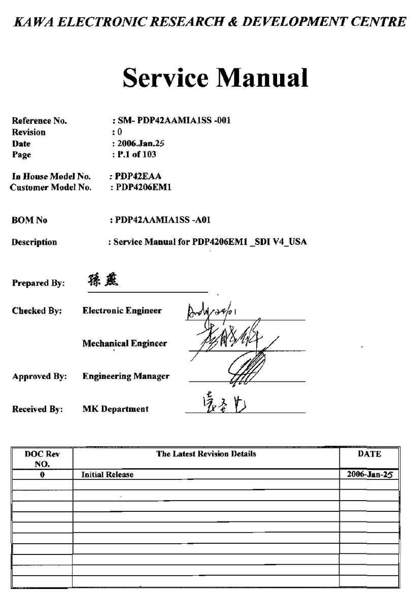
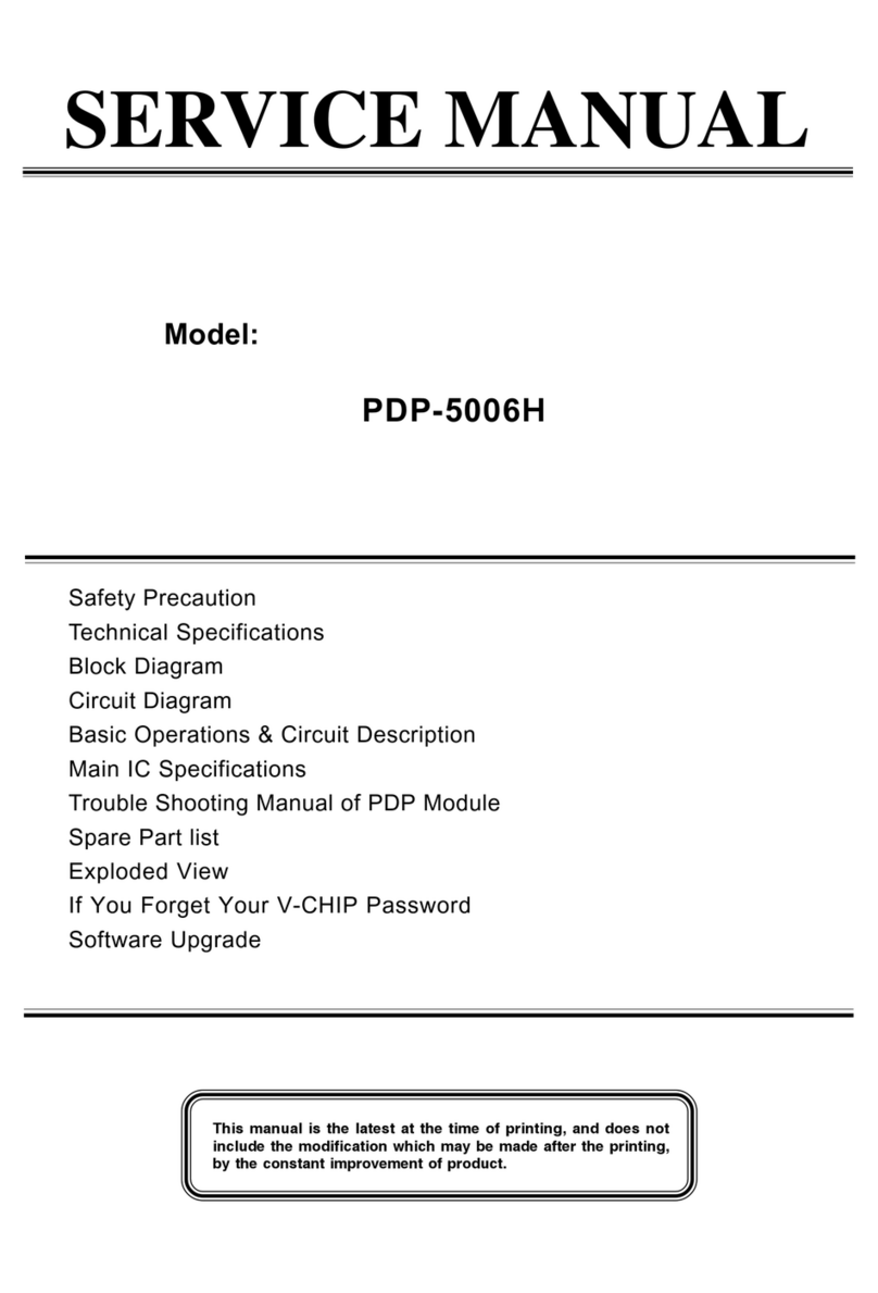
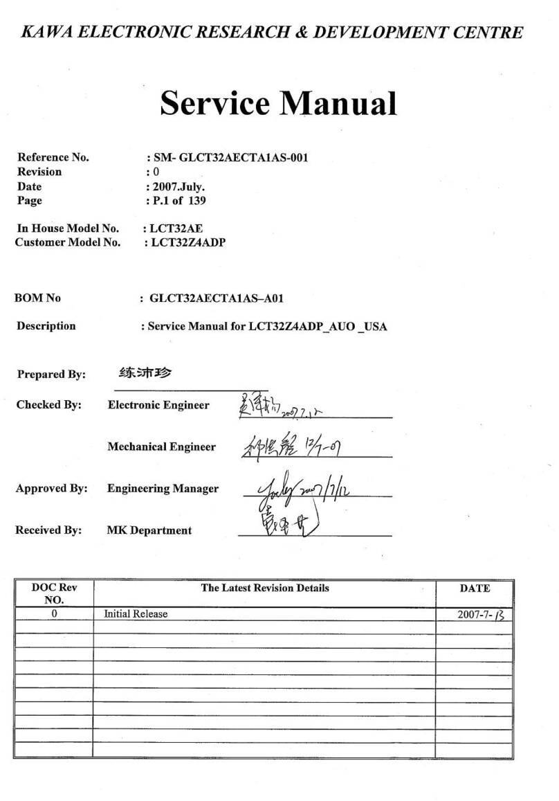
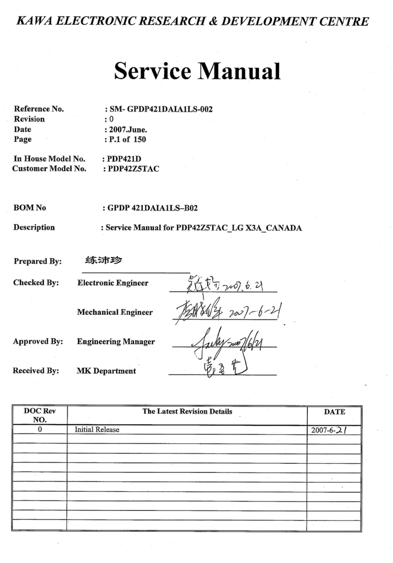
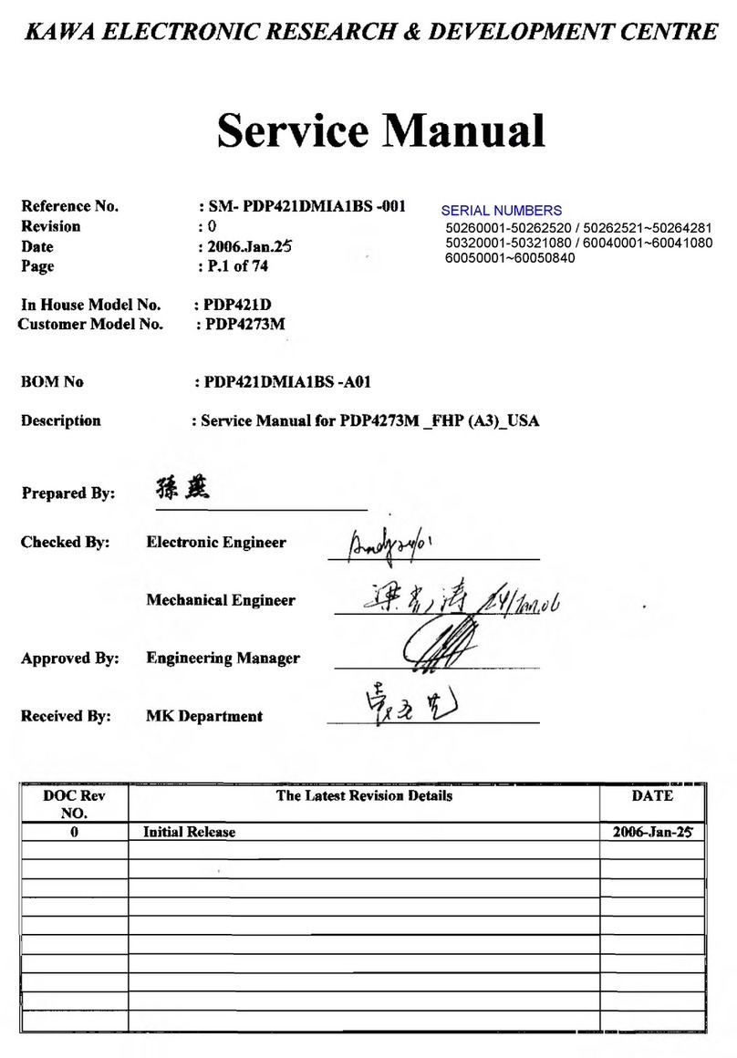
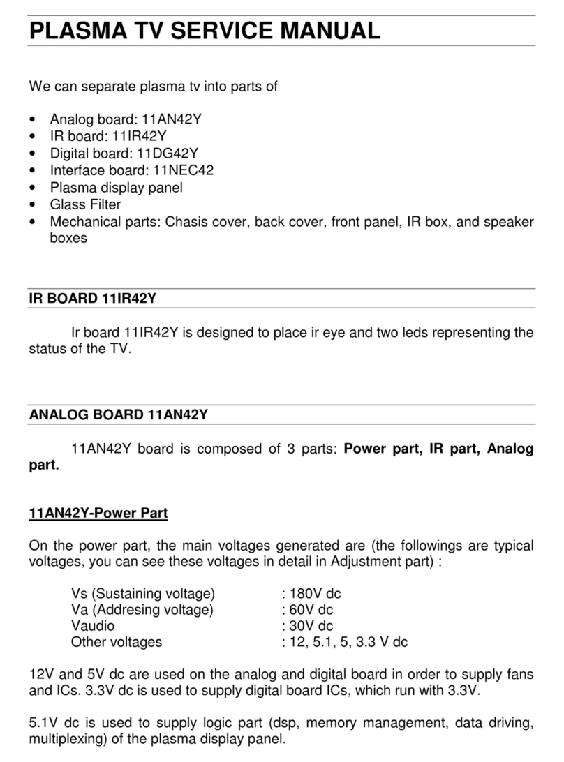
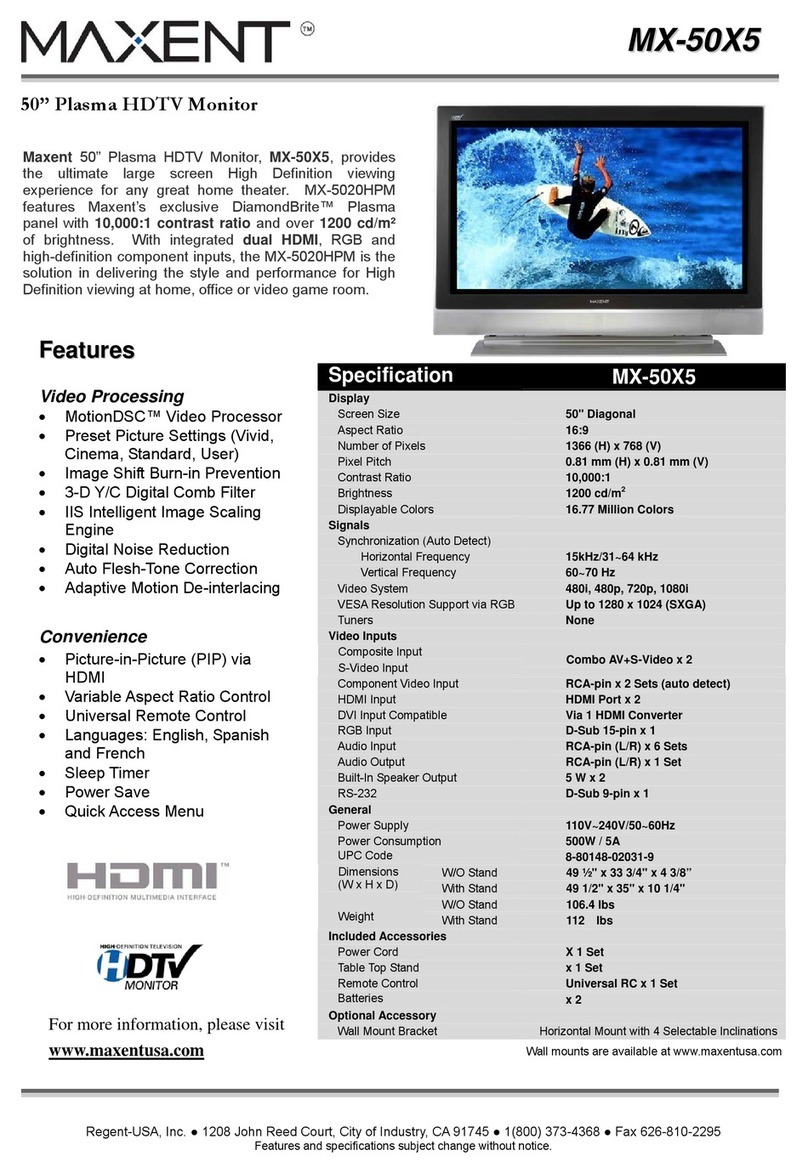
Akai PDP4273M User manual


AKAI
SERVICE MANUAL
Model: PDP4273M
1
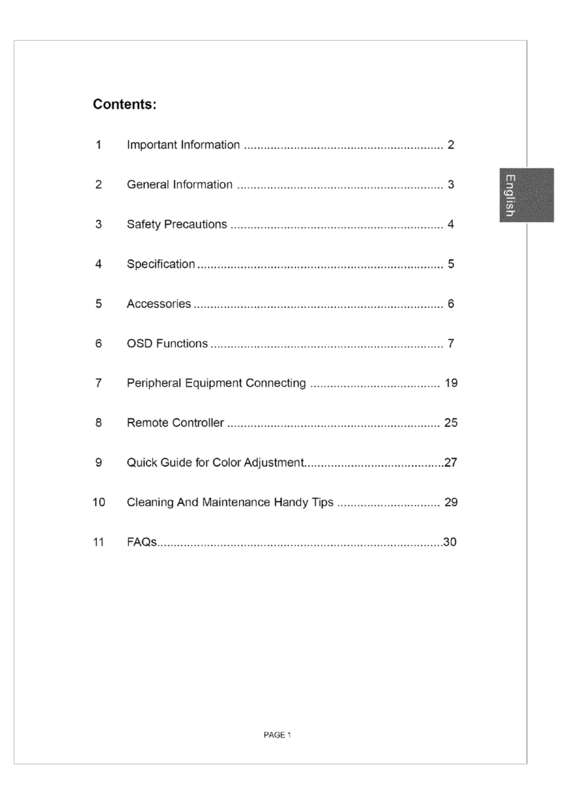
1. Safety Precaution.................................................................................................................2~3
2. Technical Specification ......................................................................................................4~10
3. C ircuit Di agram...................................................................................................................11 ~3 3
4. Ba ic Operation & Circuit De cription
........................................................................... 34~36
5. Main IC Information............................................................................................................37
6. Panel Information................................................................................................................38~67
7. Spare Pare Li t.....................................................................................................................68~71
8. Exploded View.....................................................................................................................72
9. If you forget your V-Chip Pa word................................................................................. 73
10. Software Upgrade................................................................................................................74~82
This manual is the latest at the time of printing, and does not
include the modification which may be made after the printing,
by the constant improvement of product.
1

Safety Precaution
ACAUTION
RISK OF ELECTRIC SHOCK
DO NOT OPEN A
CAUTION: TO REDUCE THE RISK OF
ELECTRIC SHOCK DO NOT REMOVE COVER
(OR BACK). NO USER-SERVICEABLE PARTS
INSIDE. REFER SERVICING TO QUALIFIED
SERVICE PERSONNEL ONLY.
A
A
The lightning flash with arrowhead symbol,
within an equilateral triangle, is intended to
alert the user to the presen e of uninsulated
“dangerous voltage” within the produ t's en lo
sure that may be of suffi ient magnitude to
onstitute a risk of ele tri sho k to persons.
The ex lamation point within an equilateral
triangle is intended to alert the user to the
presen e of important operating and
maintenan e (servi ing) instru tions in the
literature a ompanying the applian e.
2.
PRECAUTIONS DURING
SERVICING
In addition to safety, other parts and
assemblies are spe ified for onforman e with
su h regulations as those applying to spurious
radiation. These must also be repla ed only
with spe ified repla ements.
Examples: RF onverters, tuner units, antenna
sele tion swit hes, RF ables, noise-blo king
apa itors, noise-blo king filters, et .
Use spe ified internal Wiring. Note espe ially:
1) Wires overed with PVC tubing
2) Double insulated wires
3) High voltage leads
Use spe ified insulating materials for hazardous
live parts. Note espe ially:
1) Insulating Tape
2) PVC tubing
3) Spa ers (insulating barriers)
4) Insulating sheets for transistors
5) Plasti s rews for fixing mi ro swit hes
When repla ing AC primary side omponents
(transformers, power ords, noise blo king
apa itors, et .), wrap ends of wires se urely
about the terminals before soldering.
1 1
5. Make sure that wires do not onta t heat
generating parts (heat sinks, oxide metal film
resistors, fusible resistors, et .)
6. Che k if repla ed wires do not onta t sharply
edged or pointed parts.
7. Make sure that foreign obje ts (s rews, solder
droplets, et .) do not remain inside the set.
MAKE YOUR CONTRIBUTION
TO PROTECT THE
ENVIRONMENT
Used batteries with the ISO symbol
for re y ling as well as small a umulators
(re hargeable batteries), mini-batteries ( ells) and
starter batteries should not be thrown into the
garbage an.
Please leave them at an appropriate depot.
WARNING:
Before servi ing this TV re eiver, read the
SAFETY INSTRUCTION and PRODUCT
SAFETY NOTICE.
SAFETY INSTRUCTION
The servi e should not be attempted by anyone
unfamiliar with the ne essary instru tions on this
apparatus. The following are the ne essary
instru tions to be observed before servi ing.
1. An isolation transformer should be onne ted in
the power line between the re eiver and the
AC line when a servi e is performed on the
primary of the onverter transformer of the set.
2. Comply with all aution and safety related
provided on the ba k of the abinet, inside the
abinet, on the hassis or pi ture tube.
3. To avoid a sho k hazard, always dis harge the
pi ture tube's anode to the hassis ground
before removing the anode ap.
4. Completely dis harge the high potential voltage
of the pi ture tube before handling. The pi ture
tube is a va uum and if broken, the glass will
explode.
2


PRODUCT SAFETY NOTICE
5. When repla ing a MAIN PCB in the abinet,
always be ertain that all prote tive are
installed properly su h as ontrol knobs,
adjustment overs or shields, barriers, isolation
resistor networks et .
6. When servi ing is required, observe the original
lead dressing. Extra pre aution should be given
to assure orre t lead dressing in the high
voltage area.
7. Keep wires away from high voltage or high
tempera ture omponents,
8. Before returning the set to the ustomer,
always perform an AC leakage urrent he k
on the exposed metalli parts of the abinet,
su h as antennas, terminals, s rewheads,metal
overlay, ontrol shafts, et ., to be sure the set
is safe to operate without danger of ele tri al
sho k. Plug the AC line ord dire tly to the
AC outlet (do not use a line isolation
transformer during this he k). Use an AC
voltmeter having 5K ohms volt sensitivity or
more in the following manner.
Conne t a 1.5K ohm 10 watt resistor paralleled
by a 0.15pF AC type apa itor, between a
good earth ground (water pipe, ondu tor et .,)
and the exposed metalli parts, one at a time.
Measure the AC voltage a ross the ombination
of the 1.5K ohm resistor and 0.15 uF
apa itor. Reverse the AC plug at the AC
outlet and repeat the AC voltage measurements
for ea h exposed metalli part.
The measured voltage must not ex eed 0.3V
RMS.
This orresponds to 0.5mA AC. Any value
ex eeding this limit onstitutes a potential
sho k hazard and must be orre ted
immediately.
The resistan e measurement should be done
between a essible exposed metal parts and
power ord plug prongs with the power swit h
"ON". The resistan e should be more than
6M ohms. AC VOLTMETER
ctc. AC Leakage Current Check
Many ele tri al and me hani al parts in this
apparatus have spe ial safety-related
hara teristi s.
These hara teristi s are offer passed
unnoti ed by visual spe tion and the prote tion
afforded by them annot ne essarily be obtained
by using repla ement omponents rates for a
higher voltage, wattage, et .
The repla ement parts whi h have these
spe ial safety hara teristi s are identified by A
marks on the s hemati diagram and on the parts
list. Before repla ing any of these omponents,
read the parts list in this manual arefully. The
use of substitute repla ement parts whi h do not
have the same safety hara teristi s as spe ified
in the parts list may reate sho k, fire, or other
hazards.
9. Must be sure that the ground wire of the AC
inlet Is onne ted with the ground of the
apparatus properly.
3

Technical Specifications PDP4273M1
1. Standard Test Conditions
All tests shall be performed under the following onditions, unless otherwise spe ified
1.1 Ambient light : 150ux (When measuring lB, the ambient luminan e
£0.1Cd/m2)
1.2 Viewing distan e : 50 m in front of PDP
1.3 Warm ud time : 30 minutes
1.4 PDP Panel fa ing : no restri ted
1.5 Measuring Eguipment : Minolta CA 100 photometer
1.6 Magneti field : no restri ted
1.7 Control settings : Brightness, Contrast, Tint, Color set at Center(50)
1.8 Power input : 120Va , 60Hz
1.9 Ambient temperature : 20° C ± 5°C (68°F ± 9°F)
1.10 Display mode : Resolution 1024 (H) x 1024 (V) Pixels
1.11 Other onditions :
1.11.1 With image sti king prote tion of PDP module, the luminan e will des end
by time on a same still s reen and rapidly go down in 5 minutes. When
measuring the olor tra king and luminan e of a same still s reen, be sure
to a omplish the measurement in one minute to ensure its a ura y.
1.11.2 Due to the stru ture of PDP, the extra-high-bright same s reen should not
hold over 5 minutes for fear of branding on the panel.
4

5

Technical Specifications PDP4273M1
4.2 Audio input
Audio lnput(L/Rx5) : 1 for DVI / D-Sub
2 for YPbPr
1 for S-Video
1 for A V
4.3 Audio output
Audio Output (L/Rx1) : Monitor out(LVR)
SPDIF Coaxial x 1 (only for HDMI)
5. Environment
5.1 Operating environment
5.1.1 Temperature 5° to 33°C
5.1.2 Relative humidity: 20% to 85%(non- ondensing)
5.2 Storage and Transport
5.2.1 Temperature -20°C to 60°C (-4° to 1403F)
5.2.2 Relative humidity: 5% to 95%
6. Panel Chara teristi s
6.1 Type 42LGX3
6.2 Size 1005(H)x 597(V)x60.7(D)±1 mrn
6.3 Aspe t ratio 16:9
6.4 Viewing angle : Over 160°
6.5 Resolution 1024 x 168
6.6 Weight Approx 16kg
6.7 Color 1073.7 million olors by ombination of 10 bits R,G,B digi
6.8 Contrast 10000:1, Peak White, display rate: 1%, In dark room.
6.9 Peak brightness 1200 d/m\ Peak White, Max. gradation, display rate: 1%.
6.10 Color Coordinate Uniformity: Contrast; Brightness and Color ontrol
at normal setting
Test Pattern Full white pattern
Average of point A,B,C,D and E +/- 0.01
« . «
: w
@ 0
ó

7

Technical Specifications PDP4 73M1
:tI5 ' © ' Cfj'i
id ) CD <D|
i® ,_<3>
t e / ( P " i
■ g e b l Q .
■«t va- . r~~— .1
t e o >
- M i
oooa
■ Hof ■ • P.Sfa»
O ! ! O
(ZI
©
12 Remote Control
IX) Standby(Ci)): Press this button to
turn off to standby and turn on from
standby.
ED Mute(M): Press this button to quiet
the sound system. Press again to [Tj
rea tivate the sound system.
¡2 Number buttons: Use these
buttons to enter the password. ^
@ Sour e: Press this button to sele t
the signal sour es. AV, S-Video,
YPbPr 1, YPbPr 2, VGA or IIDMI. “
III Sleep: Press this button to sele t ®
the sleep time, su h as “15 Min, 30
Min, 60 Min, 90 Min, 120 Min or off’.
© VOL +/- : Press these buttons to
in rease or de rease the volume. (HI
(Z) P. Mode : Press the button to _
sele t different pi ture effe t, su h
as “Normal, Vivid, Hi-Bright, User
or Cinema”.
ED System: Press this button to sele t
the olor system, su h as “AUTO
or NTSC 3.58”. (Only for AV or
S-Video)
® These buttons have no fun tion.
Pressing the button will display:
"This button is not in use.”
§§ Enter : Press to enter or onfirm.
4 I ► : They are used as < i ► buttons in the OSD Menu s reen.
▲ I ▼ : They are used as A / ▼ buttons in the OSD Menu s reen.
HI) Exit: Press this button to exit the OSD Menu.
JH Menu: Press this button to pop up the OSD Menu and press it again to exit
the OSD Menu.
Ill) Freeze: Press this button to hold on the s reen. Press again to normal.
Jm) Display: Press the button to display the sour e information.
Ill) S. Mode: Press the button to sele t different sound effe t, su h as “Normal,
News, Cinema, Con ert or User”.
B V-Chip: Press this button to enter the V-Chip Fun tion. (Only for AV or S-Video)
@3 P. Size: Press this button, the pi ture will hange a ording to Full, 4:3 or
Panorami , (ina tive for VGA)
HI C/C: Press this button to enter the Closed Caption Fun tion. (Only for AV or
S-Video)
8

Technical Specifications PDP4273M1
13. Support the Signal Mode
A. VGA Mode
Resolution Horizontal
Frequen y
(KHz)
Verti al
Frequen y
(Hz)
31.50 60.00
37.86 72.81
35.16 56.25
37.90 60.32
OUUX DUU 46.90 75.00
48.08 72.19
1024x 768 48.40 60.00
B.YPbPr Mode
Resolution Horizontal
Frequen y
(KHz)
Verti al
Frequen y
(Hz)
480i 15.734 59.94
480p(720x480) 31.468 59.94
720p(1280x720) 45.00 60.00
1080i(1920x1080) 33.75 60.00
C.HDMI Mode
Resolution Horizontal
Frequen y
(KHz)
Verti al
Frequen y
(Hz) '
480p 31.468 59.94
720p 45.00 60.00
1080i 33.75 60.00
- When the signal re eived by the Display ex eeds the allowed range, a warning message
shall appear on the s reen.
- You an onfirm the input signal format from the on-s reen.
9

10

U i
11

- Main (Video) board
- Keypad board
- Remote control receiver board
- External L/R Speakers board
- Remote control board
Circuit Diagram
12

13

14

15

16

17

18

19
Other manuals for PDP4273M
4
Table of contents
Other Akai Plasma TV manuals

Akai
Akai LCT32Z4ADP User manual

Akai
Akai PDP4273M1 User manual

Akai
Akai PDP4273M User manual

Akai
Akai PDP4294LV1 User manual

Akai
Akai PDP6065TAC User manual

Akai
Akai PDP5074HNC User manual

Akai
Akai PDP4206EM1 User manual

Akai
Akai PDP42Z5TA - 42" Plasma TV User manual

Akai
Akai PDP50Z6TA User manual

Akai
Akai PDP42Z5TA - 42" Plasma TV User manual