ModelNo:14RBS3Wn
Version 1.0
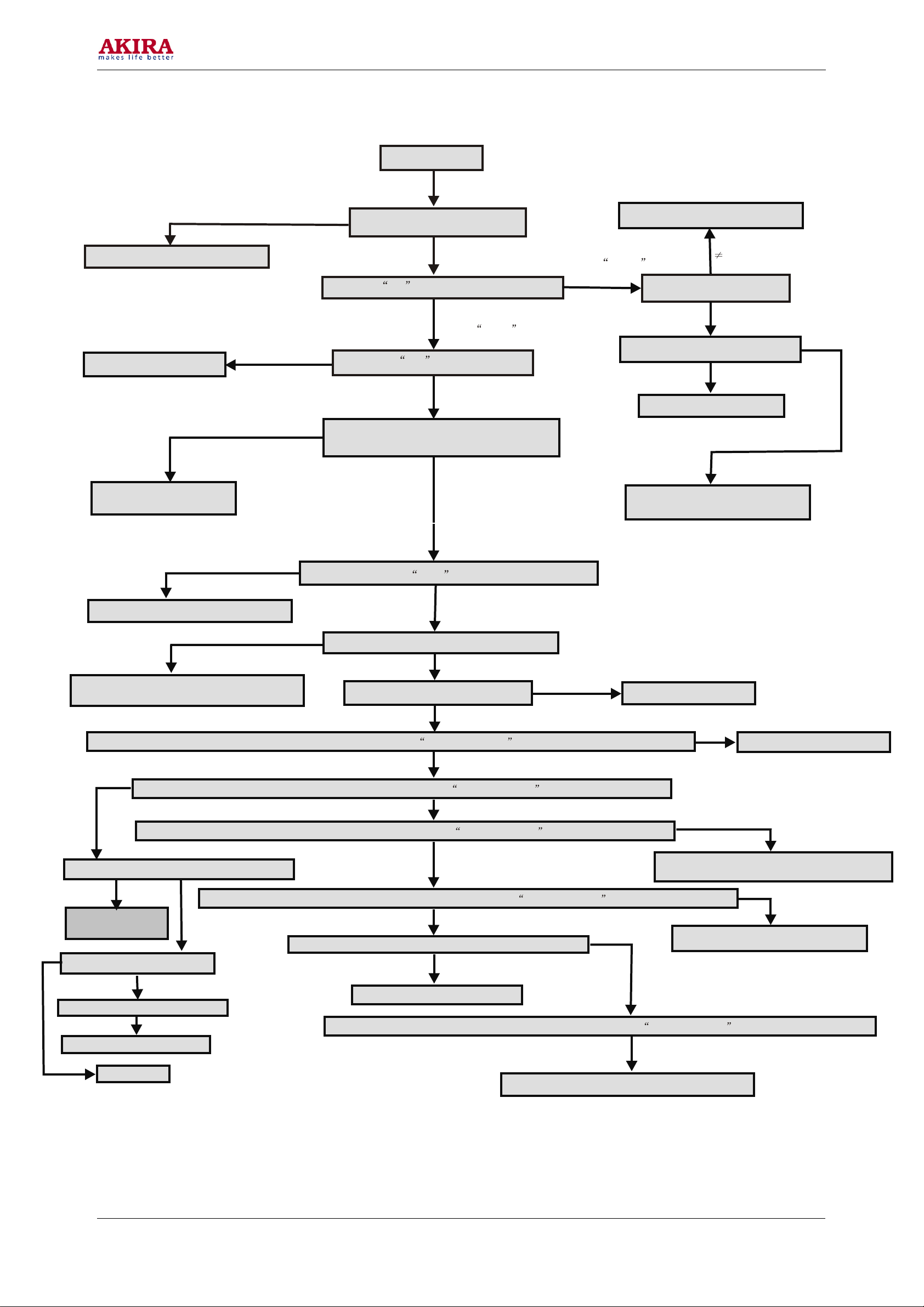
No picture
Check if U101has input signal
Check RF signal input and adaptor
No
Check the VT voltage when auto searching
Yes
The voltage on the C573
Check the MB voltage on U101
Out of the 0-33V range
In the 0-33V range
Check R576,C573,VD573,UPC574
Check the voltage on the C704
=33V
33V
Check R707,C103,U101
0-33V
Check R706,R705,VD701,R704
R703,V701,R701,R702,N701
No variation
Check L103,N203,U101
0V
The voltage between band1 and band2 vary
from 0V to 5V or not when auto searching
5V
Check R120,R121,R714
R715,N701,U101
0V
Yes
Exam the voltage of AGC on U101 without antenna
Yes
Check R104,R204,C206,U101,N201
Test the voltage on pin 1,3,17,28,36 of N201
<2V
>3.8V
Check L206 ,C122, N101,C120, R258 ,R569
C554,VD554,N201,L209,L201,R218,VD205
0V
Test the voltage on pin46 of N201
9V
Check N203,L203,N201
0V
Observe if there is snow-noise-wave disturbance on the CRT via using Signal-input way by touching pin 6 and pin8 of N201
5V
Check N203,L203,C239,N201
No
Yes
Observe if there is snow-noise-wave disturbance on the CRTvia using Signal-input way by touching pin 47 of N201
Check if the voltage on pin28 of N201 is 4.6V
Yes
Check C244,C245,
N201,L205,R228
The voltage on pin4 of N201
Check N201
The voltage on pin13 of N701
Check R720,N701,R202
<2V Yes
0V
2.38V
0V
Observe if there is snow-noise-wave disturbance on the CRTvia using Signal-input way by touching pin 35 of N201
No
Observe if there is snow-noise-wave disturbance on the CRTvia using Signal-input way by touching pin 39 of N201
No
Yes
Check C211,R252-255,V804,V204,V202,N201
ZN01,LN01,RN03,RN02,R244,R240,R227
Test if there is the sync signal on the pin36 of N701
No
Check R222,R223,V201,C228,R229
Yes
Check R780,C715,N701,N201
No
Observe if there is snow-noise-wave disturbance on the CRTvia using Signal-input way by touching pin 18-20 of N201
Yes
Check R206-R208,VD202-VD204,XS601,N201
No
9