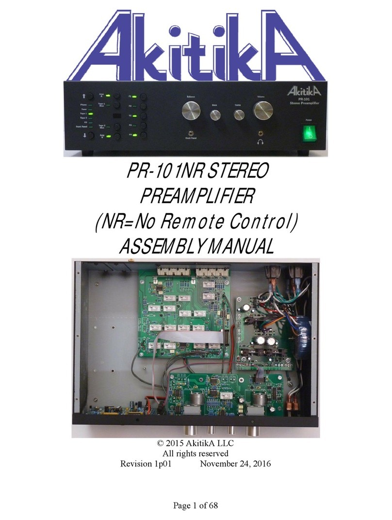
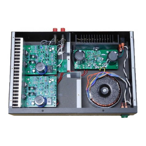
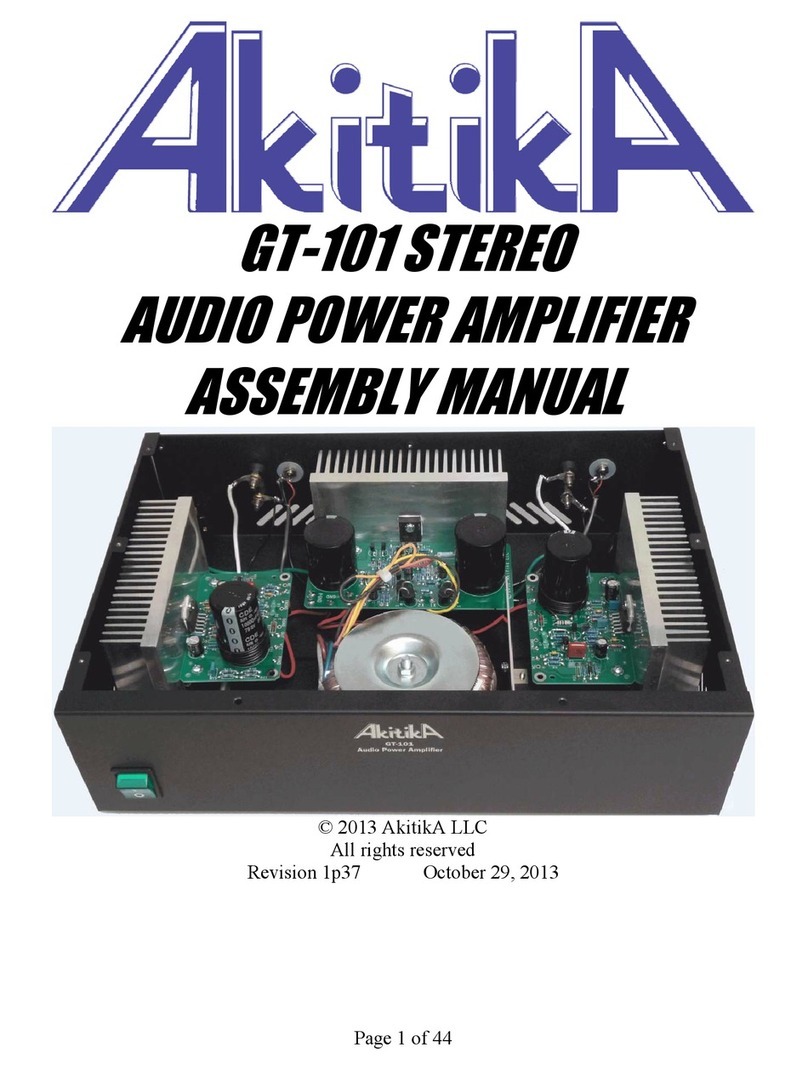
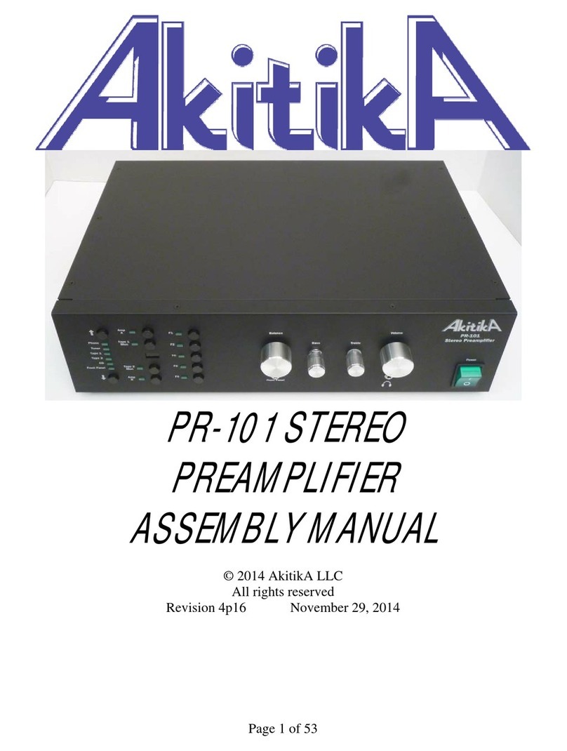
AkitikA DYNACO STEREO 120 User manual

Page 1 of 32
UPDATING THE
DYNACO STEREO 120
SOLID STATE
POWER AMPLIFIER
REV B
© 2013 AkitikA, LLC
All rights reserved
Revision 1.17
Jul 27, 2013

Page 2 of 32
Table of Contents
Table of Contents................................................................................................................ 2
Table of Figures .................................................................................................................. 3
Section 1: About this Manual ............................................................................................. 4
Who Should Attempt this Project? ................................................................................. 4
Tools You’ll Need........................................................................................................... 4
Project Overview ............................................................................................................ 5
Important Safet Notes ................................................................................................... 5
About Components ......................................................................................................... 5
Recommended Solder ..................................................................................................... 5
Section 2: Saving the Stuff that Should Be Saved.............................................................. 6
Opening the Amplifier .................................................................................................... 6
Cutting the wires on the old amplifier modules.............................................................. 6
Removing the LEFT channel module......................................................................... 6
Removing the RIGHT channel module ...................................................................... 7
Removing C7 RIGHT ............................................................................................... 10
Removing C7 LEFT.................................................................................................. 10
Removing the Output Zobel Networks ..................................................................... 10
Salvaging the Heat Sinks from the Amplifier Modules................................................ 12
Section 3: Checking the Stereo 120 Power Suppl .......................................................... 12
Prepare and Connect the Test Load .............................................................................. 12
Test the Power Suppl .................................................................................................. 13
The Voltage is Much More than 75.6 volts .................................................................. 13
The Voltage is Much Less than 68.4 volts.................................................................... 13
There’s No Voltage at All............................................................................................. 14
Section 4: Assembling the Amplifier Circuit Boards ....................................................... 14
Install the Resistors ....................................................................................................... 15
Install the Small Capacitors and the Diodes ................................................................. 17
Last Capacitors and the Transistors .............................................................................. 18
Winding the Output Inductor ........................................................................................ 19
Solder the LM3886 into the Board ............................................................................... 20
Final Inspection of the Circuit Board............................................................................ 22
Mounting the Updated Amplifier Board to the Heat Sink............................................ 23
Section 5: Wiring In the Updated Amplifier Modules...................................................... 24
Revise the Grounding S stem....................................................................................... 24
Revise the Power S stem.............................................................................................. 25
Complete the Ground S stem ....................................................................................... 26
Wiring the Inputs .......................................................................................................... 26
Wiring the Outputs........................................................................................................ 27
Connecting the Left Channel Amplifier Module .......................................................... 27
Connecting the Right Channel Amplifier Module........................................................ 28
Making the Speaker Binding Posts User Friendl ........................................................ 29
Section 6: Testing the Completed Amplifier .................................................................... 29
Test #1........................................................................................................................... 29
Test #2........................................................................................................................... 30
Page 3 of 32
Test #3........................................................................................................................... 30
Test #4........................................................................................................................... 30
Resistor Color Code...................................................................................................... 32
Table of Figures
Figure 1-Location of the four screws that hold the cover to the base................................. 6
Figure 2-Location diagram for cutting wires ...................................................................... 8
Figure 3-After the Amplifier Modules have been removed................................................ 9
Figure 4- Removal of components is completed .............................................................. 11
Figure 5- Separating heat sinks and circuit boards ........................................................... 12
Figure 6-Connecting a test load to the power suppl ....................................................... 13
Figure 7-Empt the amplifier components into a soup bowl............................................ 14
Figure 8-Closeup of Completed Amplifier board ( our big cap ma look a bit different)
........................................................................................................................................... 15
Figure 9-First four resistors are installed, leads bent on the back side, soldered, then
clipped............................................................................................................................... 15
Figure 10-Zero Ohm R22 installation detail..................................................................... 17
Figure 11-showing LED cathode orientation.................................................................... 18
Figure 12-Starting to wind the output inductor................................................................. 20
Figure 13-finishing step for the output inductor ............................................................... 20
Figure 14-Showing method of attaching brackets to the PCB.......................................... 21
Figure 15-Template for checking mounting height of LM3886....................................... 21
Figure 16-LM3886 installation step three, just the corner pins are soldered.................... 22
Figure 17-The LM3886 sits up off the board to avoid shorts between the front and back
rows of pins. The bod should be at right angles to the circuit board .............................. 22
Figure 18-Mounting assembled PCB to heat sink ............................................................ 23
Figure 19-a completed amplifier module.......................................................................... 24
Figure 20-Rewiring the Power and Half the Grounds ...................................................... 26
Figure 21-completed wiring.............................................................................................. 27
Figure 22-Schematic of amplifier module ........................................................................ 31
Figure 23-demonstrating the resistor color code .............................................................. 32

Page 4 of 32
Section 1: About this Manual
This manual gives ou all the information ou need to bring our Solid State D naco
Stereo 120 Power Amplifier up to date using UpdateM D naco replacement modules.
This manual covers the Rev B design. It’s ver similar to the original design, but includes
most (but not all of) the improvements made in the Akitika GT-101 design:
• Added components give quiet turn-off even when paired with C12 Upgrade kits
(the original design required the quiet turn-off mod to be retro-fit into the board)
• Value changes slightl increase the maximum output power prior to clipping.
• The PCB has a different grounding arrangement which allows the LED’s to run
more brightl .
• The GT-101 uses 0.1% tolerance gain setting resistors. The modules described
herein use standard 1% tolerance gain setting resistors.
The onl part of our Stereo 120 that reall needs to work is the power suppl . With this
kit, ou’ll build good sounding, highl reliable amplifiers to replace the original amplifier
modules.
Check www.updatemydynaco.com for “Hints for Kit Builders” before you begin
assembly
Who Should Attempt this Project?
You can build this kit and update our D naco Stereo 120 if ou can:
1. solder (using normal rosin core solder and a soldering iron).
2. use simple hand tools like screwdrivers, wire cutters, and pliers.
3. read and follow directions.
It helps if ou:
1. know a bit about electronics, or
2. have a friend who knows a bit about electronics
3. can get to YouTube to watch a video about the assembl process
Tools You’ll Need
You’ll need the following tools to update our Stereo 120:
1. flat blade screwdriver for #6 screws
2. Phillips screwdriver (#2)
3. pliers or nut drivers suitable for #6 hardware (5/16” nut driver or hex wrench)
4. needle nose pliers (helpful, but not strictl necessar )
5. pencil t pe soldering iron of 25 to 50 Watts (no huge honking soldering guns or
blowtorches)
6. wire cutters and strippers
7. multi-meter (helpful, but not strictl necessar )
8. magnif ing glass, to verif identification codes on the 3 COG capacitors

Page 5 of 32
Project Overview
The project consists of the following steps:
1. Removing the old amplifier modules, saving some parts for re-use.
2. Checking out the old D naco Stereo 120 power suppl .
3. Assembling the updated amplifier module PC Boards.
4. Mounting the updated amplifier modules to the heat sinks.
5. Wiring in the updated amplifier modules.
Important Safet Notes
B purchasing this kit, ou have agreed to hold AkitikA, LLC harmless for an injuries
ou ma receive in its assembl and/or use. To prevent injuries:
• Wear safet glasses when soldering to prevent e e injuries.
• Alwa s unplug the power before working on the amplifier.
• Large capacitors hold lots of energ for a long time. Before ou put our hands
into the amplifier:
o Pull the AC plug!
o Wait 1 full minute for the capacitors to discharge!
• Remove jewelr and rings from our hands and wrists, or an thing that might
dangle into the amplifier.
• If working in the amplifier, keep one hand in our pocket, especiall if ou’re
near the power suppl or power suppl wires. This can prevent serious shocks.
• Build with a budd nearb . If ou’ve ignored all the previous advice, the can
dial 911 or get ou to the hospital.
About Components
We reserve the right to make design/or component changes at an time without prior
notification.
Recommended Solder
The kit must be assembled with 60/40 Rosin Core solder. The recommended diameter is
0.032 inches. Among man such sources of solder, I have used Radio Shack part number
64-009. It contains 8 oz. of solder, which is much more than ou’ll need to assemble the
kit.

Page 6 of 32
Section 2: Saving the Stuff that Should Be Saved
Opening the Amplifier
1. Make sure the amplifier is unplugged. f it was recently powered allow the amp
to sit for one full minute before proceeding.
2. Remove the four screws along the outside edge of the bottom that hold the cover
in place (see Figure 1).
Figure 1-Location of the four screws that hold the cover to the base
3. Holding both the top and bottom of the amplifier, flip it over.
4. Lift the perforated metal top off of the amplifier.
Cutting the wires on the old amplifier modules
Refer to Figure 2. It shows where the wires must be cut to remove the old amplifier
modules. Those cuts are detailed in the text below. Each cut is marked b an X.
Removing the L FT channel module
1. To remove the LEFT channel module, cut the following wires close to the end
that connects to the LEFT channel PC-14 module. Make onl one cut per wire,
leaving the wire attached at the end farthest from the LEFT PC-14 module.
a. E elets 8, 9, 10, 11, 12, and 13
2. Cut the wire that attaches to E elet 5 of the PC-15 power suppl circuit board
close to the PC-15 circuit board.
3. Loosen the two screws that hold the left channel heat sink in place (note that one
of the screws holds a mounting foot
1
). Save the hardware for later re-use.
4. Cut the red wire that connects to Q5’s collector, close to the lug. Although there
are multiple wires on the collector, onl cut the wire that connects to C12.
1
If our mounting feet are falling apart, ou can order a replacement set from updatem d naco.com.

Page 7 of 32
5. Cut the black wire that connects to Q6’s emitter, near the emitter. There are two
wires on the emitter... ou need onl cut the wire that runs to the black left speaker
binding post.
Save the LEFT module and mounting hardware. We will re-use the heat-sink and some
other bits as described in “Salvaging the heat sinks from the amplifier modules”.
Removing the RIGHT channel module
6. To remove the RIGHT channel module, cut the following wires close to the end
that connects to the RIGHT channel PC-14 module. Make onl one cut per wire,
leaving the wire attached at the end farthest from the RIGHT PC-14 module.
a. E elets 8, 9, 10, 11, 12, and 13
7. Loosen the two screws that hold the RIGHT channel heat sink in place (note that
one of the screws holds a mounting foot
2
). Save the hardware for later re-use.
8. Cut the red wire that connects to Q5’s collector, close to the lug. Although there
are multiple wires on the collector, onl cut the wire that connects to C12.
9. Cut the black wire that connects to Q6’s emitter, near the emitter. There are two
wires on the emitter... ou need onl cut the wire that runs to the black RIGHT
speaker binding post.
Save the RIGHT module and mounting hardware. We will re-use the heat-sink and some
of the other bits as described in “Salvaging the heat sinks from the amplifier modules”.
2
If our mounting feet are falling apart, ou can order a replacement set from updatem d naco.com.

Page 8 of 32
Figure 2-Location diagram for cutting wires

Page 9 of 32
Figure 3-After the Amplifier Modules have been removed

Page 10 of 32
Removing C7 RIGHT
1. Remove the 3 sets of #6 hardware that hold C7 RIGHT to the bottom of the
chassis.
2. Unroll one foot of the wire that’s wrapped around C7 RIGHT and connects to the
RIGHT RED Binding post.
3. Cut this wire near C7 RIGHT so that about 1 foot of wire remains connected to
the RIGHT RED Binding post.
Removing C7 L FT
4. Remove the 3 sets of #6 hardware that hold C7 LEFT to the bottom of the chassis.
5. Unroll one foot of the wire that’s wrapped around C7 LEFT and connects to the
LEFT RED Binding post.
6. Cut this wire near C7 LEFT so that about 1 foot of wire remains connected to the
LEFT RED Binding post.
Removing the Output Zobel Networks
1. Clip the lead of the 0.1 uF capacitor that connects to the RIGHT RED binding
post, near the RIGHT RED Binding post.
2. Clip the lead of the 4.7 Ohm resistor that connects to the RIGHT BLACK binding
post, near the RIGHT BLACK binding post.
3. Clip the lead of the 0.1 uF capacitor that connects to the LEFT RED binding post,
near the LEFT RED Binding post.
4. Clip the lead of the 4.7 Ohm resistor that connects to the LEFT BLACK binding
post, near the LEFT BLACK binding post.
5. Remove the terminal strip and the two attached resistors and capacitors.
Figure 4 shows what the amplifier should look like when ou’ve completed this step.

Page 11 of 32
Figure 4- Removal of components is completed

Page 12 of 32
Salvaging the Heat Sinks from the Amplifier Modules
Figure - Separating heat sinks and circuit boards
Remove the four numbered nuts, bolts, and standoffs. Cut the wires that connect the
power transistors to the circuit board. Remove the four screws that hold the power
transistors to the heat sink. Remove the power transistors. Feel free to save ever thing for
a later project. Remove the Mica insulators from the heat sink. After 40 ears, the ma
be prett stuck on...a single-edged razor slid between the insulator and the heat sink ma
be the easiest wa to separate the two.
Save the old heat-sinks! The ’re part of the new assembl ! Clean off the old thermal
compound using Isoprop l Alcohol and paper towels. The best kind of isoprop l alcohol
for the job is 90%. The t pical 70% is ok, but will take more scrubbing. One motorhead
who assembled the kit reports that carburetor cleaner is ver effective. When ou use
Isoprop l alcohol or an other solvent, remember the following:
1. It’s flammable! Keep it awa from our soldering iron and don’t smoke!
2. Use it in a well ventilated area.
3. Try not to get too much on your skin!
Section 3: Checking the Stereo 120 Power Supply
The onl part of our old Stereo 120 that reall needs to work is the power suppl . After
ou’ve completed the previous section, onl the power suppl remains in the chassis.
This section describes how to verif proper operation of the power suppl .
Make sure that the power cord is out, and has been out for at least 1 minute before
starting this section.
Prepare and Connect the Test Load
We’ll rec cle parts of the amplifier boards to make a test load resistor for the power
suppl . If ou know that our power suppl and regulator are working correctl , ou ma
skip ahead to Section 4, Building the amplifier boards.
1. Keeping the leads as long as possible, remove two 300 Ohm power resistors from
one of the PC-14 circuit boards. If ou have an doubts about the resistors, check
them with an ohm-meter.
2. Connect the two resistors in series, twisting and soldering.
3. Connect the series resistors across C12. Figure 6 shows how the test circuit will
look. The ground side connection is a bit round-about, but it’s there none the less.

Page 13 of 32
Figure 6-Connecting a test load to the power supply
Test the Power Suppl
4. Make sure that neither the resistors nor their connections rest on the chassis. This
is important.
5. Make sure that none of the other dangling wires is making contact with an thing
else.
6. When ever one is clear of the amplifier, plug it in, and turn it on.
7. Measure the DC voltage on the terminals of C12.
8. The voltage should be between 68.4 and 75.6 Volts, with a nominal voltage of 72
Volts. If it falls in this range, our power suppl checks out. Remove the load
resistors and move onto section 4.
The Voltage is Much More than 75.6 volts
Most likel the pass transistor is shorted. However, repairing the power suppl module is
be ond the scope of this manual. You can complete Section 4 but don’t move on to
Section 5 until ou have repaired the module. Check www.updatem d naco.com , the
Power Suppl Circuit Description, for more information.
The Voltage is Much Less than 68.4 volts
Most likel the pass transistor is open. However, repairing the power suppl pass module
is be ond the scope of this manual. Don’t continue until ou have fixed the module.
Check www.updatem d naco.com , the Power Suppl Circuit Description, for more
information.

Page 14 of 32
There’s No Voltage at All
Check:
1. Is the AC socket powered?
2. Is the amp plugged in?
3. Is the power turned on?
Remove the power, check and replace the fuse with a properl rated fuse. Sometimes,
fuses just get tired. Sometimes the blow to prevent a disaster. At this point, we’re not
sure what the case is here.
Maintaining a respectful distance, power the amp again, and observe if the fuse blows. If
it blows quickl , unplug the amp, and go to www.updatem d naco.com , the Power
Suppl Circuit Description, for more information. The FAQs at the end of the document
ma be especiall helpful.
At this point, if ou’re scared, confused, or nervous, find someone who knows what
the ’re doing to help ou. Above all, be safe!
Section 4: Assembling the Amplifier Circuit Boards
This section details the process of building the amplifier module circuit boards. We start
with an overview on this page. Begin b carefull empt ing the contents of one of the
envelopes marked “Akitika Stereo 120 Amp RevB Updatem d naco” into a broad soup
bowl, as shown in Figure 7.
In general, ou’ll start with the components that la closest to the board, working our
wa toward the taller components. You will:
1. Install the resistors
2. Install the small capacitors
3. Install the diodes
4. Install the LEDs
5. Install the medium size capacitors
6. Install the transistors
7. Install the big capacitor
8. Wind and install the output
inductor.
9. Install the LM3886.
Figure 7-Empty the amplifier components into a
soup bowl

Page 15 of 32
Figure 8-Closeup of Completed Amplifier board (your big cap may look a bit different)
Install the Resistors
In general, ou install the resistors b placing the bod on the silk screen side of the
board, and the leads through the indicated holes. Bend the leads over on the back of the
board to keep the resistors from falling out until our solder them in place. Tr to bend
the leads in a direction that won’t lead to solder bridges between traces that should
remain disconnected.
We recommend the following procedure:
1. Insert all the resistors of the same value, e.g. R14, R19, R20, and R21.
2. Bend the leads as described above.
3. Solder the leads on the back of the board.
4. clip the leads.
Figure 9-First four resistors are installed, leads bent on the back side, soldered, then clipped.
Turn the page for specific directions about each resistor.
When you have completed this section, there will only be one empty resistor slot, R 6, a
no-load, which will remain empty.

Page 16 of 32
Keep track of our progress b placing a check-mark in the done column as ever resistor
is installed. The resistor values can be checked with a meter, or b reading the color
code
3
. Orient the resistor with the fat brown band on the right, then ou can read both the
Color Code column and the resistor from left to right.
You will build two identical channels. We’ve provided two Done columns, Done for the
first channel you build, and Done2 for the second channel. We recommend that you build
the channels one at a time, completing the first channel, then returning to this point to
build the second channel.
Designation Value Color Code Done
1
Done
2
R14 10 Brown, Black, Black, Gold, Brown
R19 10 Brown, Black, Black, Gold, Brown
R20 10 Brown, Black, Black, Gold, Brown
R21 10 Brown, Black, Black, Gold, Brown
R13 100 Brown, Black, Black, Black, Brown
R1 48K7 Yellow, Gra , Violet, Red, Brown
R2 51K1 Green, Brown, Brown, Red, Brown
R3 100K Brown, Black, Black, Orange, Brown
R5 100K Brown, Black, Black, Orange, Brown
R7 9K09 White, Black, White, Brown, Brown
R8 11K Brown, Brown, Black, Red, Brown
R12 20K Red, Black, Black, Red, Brown
R4 1K Brown, Black, Black, Brown, Brown
R6 1K Brown, Black, Black, Brown, Brown
R9 1K Brown, Black, Black, Brown, Brown
R18 1K Brown, Black, Black, Brown, Brown
R10 1K Brown, Black, Black, Brown, Brown
R11 20K Red, Black, Black, Red, Brown
R17 1K (1
Watt) 5%
Brown, Black, Red, Gold (there are less
stripes on a 5% resistor)
4
R15 10 (1
Watt) 5%
Brown, Black, Black, Gold (there are
less stripes on a 5% resistor). This
resistor has a larger bod .
R16 This Location Remains Empt
R22 0 Ohms Use one of the cut resistor leads from a
previous step to span the R22 mounting
holes, making a 0 Ohm resistor.
Note: R8 and R18 are near each other on the board. Be careful not to mix them up!
3
See “Resistor Color Code” on page 32 to see how to read resistor color codes.
4
The resistor bod of this “1 Watt” resistor seems small to me, but the manufacturer’s data sheet swears
that it’s a 1 Watt resistor. In most cases, it will be called on to dissipate considerabl less.

Page 17 of 32
Figure 10-Zero Ohm R22 installation detail
Install the Small Capacitors and the Diodes
Now we’ll install the following small capacitors:
Designation Value Marking Done
1
Done
2
C3 220 pF 221
C4 220 pF 221
C9 47 pF 470
Here’s what these three caps look like (not to scale):
Next we install diodes D1, D4 and D5.
Be careful! Diodes have a polarity. Make sure the band on the diode aligns with
the banded end of the silk screen!
Designation Value Marking Done1 Done2
D1 1N4004 4004
D4 1N4004 4004
D5 1N4004 4004
Here’s what the diodes look like (not to scale):

Page 18 of 32
Next we install LEDs D2 and D3 (Light Emitting Diodes – the green light from these
LEDs will be of medium brightness, and thus visible in a normall lighten room.
Be careful! Light Emitting Diodes have a polarity, also! Read carefully to make
sure you’re putting the diodes in the right way! The cathode of the LED is
indicated by a bar (negative sign) molded into the package. On some packages,
there is no bar, but seen from the top, the circular outline with have a flat side.
That flat side is the cathode. Finally, if the leads are uncut, the shorter of the two
leads will be the cathode.
Designation Value Marking Done1 Done2
D2 T1 st le none
D3 T1 st le none
Figure 11-showing LED cathode orientation
Last Capacitors and the Transistors
Now, the medium tall polarized electrol tic capacitors:
C and C6 are polarized. Make sure the negative sign on the capacitors faces away from
the positive sign on the silk screen!
Designation Value Marking Done
1
Done
2
C1 100 µF, 50 V 100 µF, 50 V, and minus sign for polarit
C6 47 µF, 100 V 47 µF, 100 V, and minus sign for polarit
And the non-polarized capacitors:
Designation Value Marking Done
1
Done
2
C2 1 µF, 63 V or
100V
105K, 63 V or 100V (pillow shaped m lar
capacitor)
C5 0.1 µF, 100V µ1J100, small blue box shape
C8 0.1 µF, 100V µ1J100, small blue box shape
C10 0.1 µF, 100V µ1J100, small blue box shape

Page 19 of 32
Install the transistors. Spread the outside leads a bit to make it easier to insert them into
the board.
Orient the transistor so its body shape matches the silk-screen outline. Leave the top of
the transistor about ½” off the board! The lead length prevents stress on the body and
keeps the transistor safe from too much heat during the soldering operation.
Designation Value Marking Done
1
Done
2
Q1 2N5551, NPN 2N5551
Q2 2N5551, NPN 2N5551
Q3 2N5551, NPN 2N5551
Now install the speaker coupling capacitor:
Watch the polarity! Make sure the minus sign faces away from the plus sign on the silk
screen. That puts the minus side of the cap along the outer edge of the circuit board.
Designation Value Marking Done
1
Done
2
C11 3300 uF 63V 3300 uF, 63 WVDC
The speaker coupling capacitor will either snap or push into place. Verif once more that
ou have polarit correct, and then solder both speaker terminals to the circuit board.
This will probabl take more heat, time, and solder than an thing ou have soldered up to
now.
Winding the Output Inductor
This step takes just a bit of finesse, but if ou’ve come this far, ou have nothing to worr
about. If ou’re a bit frazzled, take a break before proceeding.
There...feel better? OK, let’s go. Just follow these steps, measuring the wire length
carefully if you want to succeed the on first shot.
1. Cut a 21 1/2” length of solid wire. A great place to get it is from the output
inductors wound around the old D naco output capacitors.
2. Strip back 3/8” of insulation from both ends of the wire. Be careful not to nick the
conductors.
3. From the component side, place one stripped end of the wire into the L1A
terminal. Route it around the output capacitor as shown in (see Figure 12) Solder
the wire into the L1A hole.
4. Wind 5 turns of wire, closel spaced, so it looks like Figure 13. When ou get to
the end of the coil, fold the end across the existing turns, toward the L1B hole.
5. Pull the end of the wire through the L1B hole, and solder it on the back of the
board.

Page 20 of 32
Figure 12-Starting to wind the output inductor
Figure 13-finishing step for the output inductor
Solder the LM3886 into the Board
This is the last step in stuffing the circuit board. B now, ou are prett good at soldering.
Your skill will help ou with this step. Just follow the instructions calml and carefull ,
and ou’ll do just fine.
1. You’ll start with one small bit of mechanical assembl as shown in Figure 14.
Use two #6-32x1/4” Phillips head screws (the have captive lock-washers) to
fasten two brackets to the solder side of the amplifier PC board. Watch the
bracket orientation, and don’t install an more fasteners at this time!
2. With the brackets attached to the PC board, use the template in Figure 15 to check
the LM3886 mounting height. If our printer has printed to the correct scale, the
square in the figure should be ver nearl 1” b 1”. Print this page, and set the
board and brackets against the page to check the LM3886’s height above the
board.
3. Match the outline of the LM3886 and the PC board to the drawing. When the
match is prett good, solder one corner pin of the LM3886. Recheck the match,
and solder an opposite corner pin (see Figure 16). If something has moved, just
reheat the corner pins and pull the LM3886 in or out as needed. If ou miss a right
angle b a little, don’t worr . Since ou’ve onl soldered two pins down, it’s eas
enough to reheat those two pins, and move the LM3886 up and down a bit until it
sits at the right height.
4. Check our work:
a. The LM3886 bod should sit up off the board to avoid short circuits
between the rows of pins (See Figure 17).
Table of contents
Other AkitikA Amplifier manuals

AkitikA
AkitikA GT-102 User manual

AkitikA
AkitikA GT100 User manual

AkitikA
AkitikA PR-101 User manual

AkitikA
AkitikA PR-101 User manual

AkitikA
AkitikA PR-101NR User manual

AkitikA
AkitikA PAT5RCA User manual

AkitikA
AkitikA PAT-4 User manual

AkitikA
AkitikA GT-101 STEREO User manual

AkitikA
AkitikA PR-101 User manual

AkitikA
AkitikA PR102NR User manual

AkitikA
AkitikA PR-101NR User manual

AkitikA
AkitikA PR-102 User manual

AkitikA
AkitikA PR-102 User manual

AkitikA
AkitikA PR-101 User manual

AkitikA
AkitikA GT-108 User manual

AkitikA
AkitikA PR-101 User manual

AkitikA
AkitikA EE-101 User manual

AkitikA
AkitikA GT-104 User manual

AkitikA
AkitikA GT-104 User manual

AkitikA
AkitikA VC102 User manual