Alacron FASTIMAGE 1300 Quick setup guide

i
FASTIMAGE 1300
CAMERA INTEGRATION GUIDE
30002-00183

ii
COPYRIGHT NOTICE
Copyright
2002 by Alacron Inc.
All rights reserved. This document, in whole or in part, may not be copied, photocopied,
reproduced, translated, or reduced to any other electronic medium or machine-readable form
without the express written consent of Alacron Inc.
Alacron makes no warranty for the use of its products, assumes no responsibility for any error
which may appear in this document, and makes no commitment to update the information
contained herein. Alacron Inc. retains the right to make changes to this manual at any time
without notice.
Document Name FastImage 1300 Camera Integration Guide
Document Number: 30002-00183
Revision History: 1.3 April 25, 2002
Trademarks:
Alacron is a registered trademark of Alacron Inc.
AltiVec is a trademark of Motorola Inc.
Channel Link is a trademark of National Semiconductor
CodeWarrior is a registered trademark of Metrowerks Corp.
FastChannel is a registered trademark of Alacron Inc.
FastSeries is a registered trademark of Alacron Inc.
Fast4, FastFrame 1300, FastImage, FastI/O, and FastVision are registered
trademarks of Alacron Inc.
FireWire is a registered trademark of Apple Computer Inc.
3M is a trademark of 3M Company
MS DOS is a registered trademark of Microsoft Corporation
SelectRAM is a trademark of Xilinx Inc.
Solaris is a trademark of Sun Microsystems Inc.
TriMedia is a trademark of Philips Electronics North America Corp.
Unix is a registered trademark of Sun Microsystems Inc.
Virtex is a trademark of Xilinx Inc.
Windows, Windows 95, Windows 98, Windows 2000,and Windows NT are
trademarks of Microsoft Corporation
All trademarks are the property of their respective holders.
Alacron Inc.
71 Spit Brook Road, Suite 200
Nashua, NH 03060
USA
Telephone: 603-891-2750
Fax: 603-891-2745
Web Site: http://www.alacron.com/

iii
TABLE OF CONTENTS
Copyright Notice ……………………………………………………………………………….. ii
Table of Contents …………………………………………………………………………….... iii
Manual Figures & Tables ……………………………………………………………………… iv
Other Alacron Manuals ………………………………………………………………………… v
System Requirements …………………………………………………………………………. v
I. INTRODUCTION................................................................................................................................ 1
A. Camera Connections................................................................................................................... 1
B. Camera Data ............................................................................................................................... 1
C. Input Taps and Camera Link Input.......................................................................................... 2
D. Control Signals to Camera......................................................................................................... 2
E. Control Signals from Camera.................................................................................................... 2
1. Input Signals from Line Cameras.................................................................................................. 2
2. Input Signals from Frame Cameras............................................................................................... 3
3. NTSC/PAL/S-Video Input Signals............................................................................................... 3
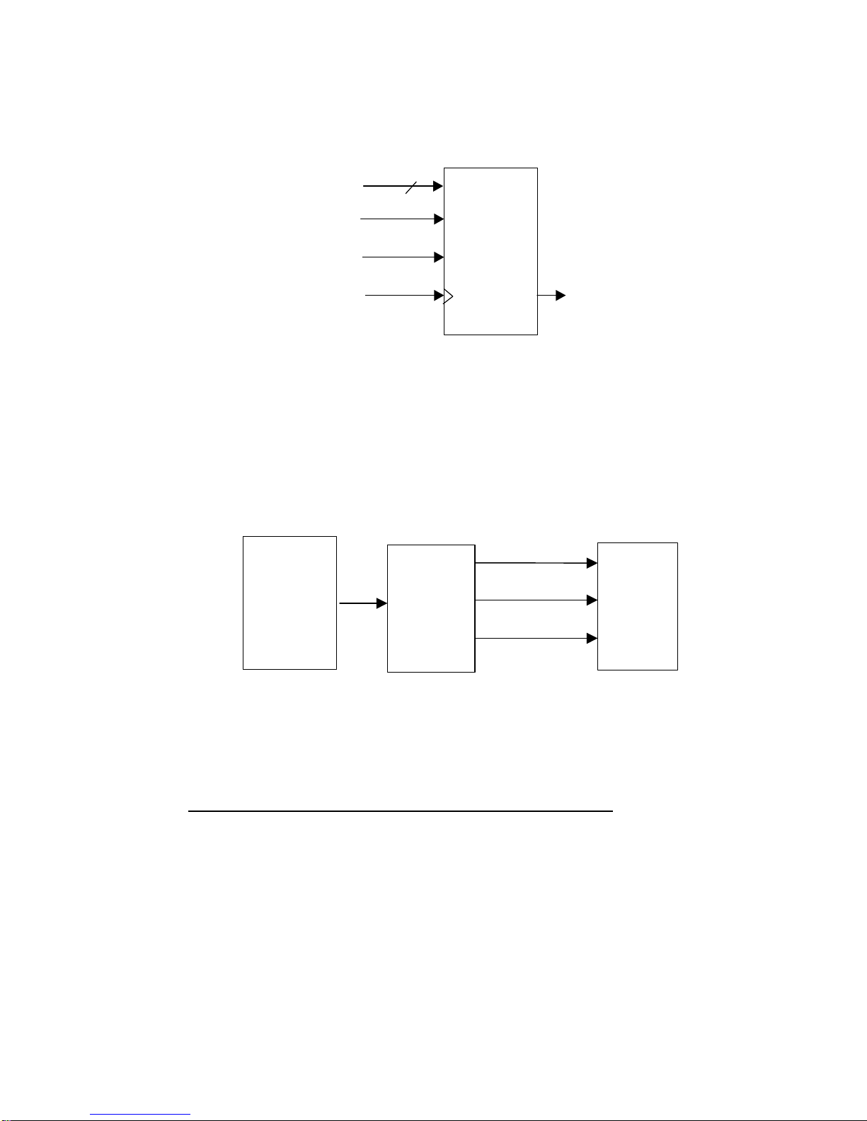
F. Image Capture, Distribution, Processing, and Output............................................................ 3
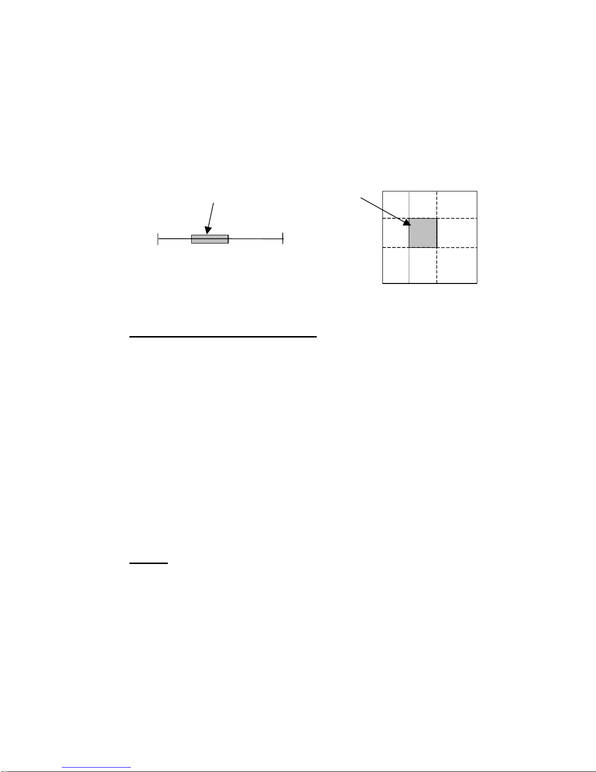
1. Region of Interest.......................................................................................................................... 4
G. Capture Profile and PAL Software........................................................................................... 4
H. Cables........................................................................................................................................... 4
I. Power Considerations..................................................................................................................... 5
II. ANALOG CAMERAS...................................................................................................................... 6
A. Analog Video Input..................................................................................................................... 6
1. NTSC/PAL Composite and S-Video Component Input................................................................ 6
2. Monochrome and RGB Analog Video Input ................................................................................ 7
B. Analog Input Connector (J1A/J1B) .......................................................................................... 8
C. Analog Camera Cables............................................................................................................... 9
1. Alacron Analog Input Cable......................................................................................................... 9
2. Camera-Specific Cables................................................................................................................ 9
D. Analog Input PAL Files.............................................................................................................. 9
1. PALs for RS-170 Analog............................................................................................................ 10
2. PALs for NTSC Analog.............................................................................................................. 10
3. Camera-Specific PAL Files......................................................................................................... 10
III. DIGITAL CAMERAS.................................................................................................................... 10
A. Digital Input.............................................................................................................................. 10
B. Digital Control Inputs .............................................................................................................. 11
C. Digital Control Outputs............................................................................................................ 11
1. Frame/Line Start and Exposure................................................................................................... 11
2. Master Clocks............................................................................................................................. 11
3. General-Purpose Outputs............................................................................................................ 12
D. Digital Input Connector (J1A/J1B)......................................................................................... 12
E. Digital Input Cables.................................................................................................................. 12
1. Alacron Digital Input Cable........................................................................................................ 12

iv
2. Camera-Specific Cables.............................................................................................................. 14
F. Digital Input PAL Files ............................................................................................................ 14
1. 16-Bit Digital Line Scan Cameras .............................................................................................. 15
2. 32-bit Digital Line Scan Cameras............................................................................................... 16
3. 8-bit Digital Area Scan Cameras................................................................................................. 16
4. 12-Bit Digital Area Scan Cameras.............................................................................................. 16
5. 32-bit Digital Area Scan Cameras............................................................................................... 16
6. Camera-Specific PAL Files......................................................................................................... 17
IV. CAMERA LINK CAMERAS......................................................................................................... 18
A. Camera Link Connector (J2)................................................................................................... 18
B. Camera Link Cable................................................................................................................... 19
V. TROUBLESHOOTING................................................................................................................. 20
VI. ALACRON TECHNICAL SUPPORT........................................................................................... 21
A. Contacting Technical Support................................................................................................. 21
B. Returning Products for Repair or Replacements................................................................... 22
C. Reporting Bugs.......................................................................................................................... 23
MANUAL FIGURES & TABLES
FIGURE PAGE SUBJECT TABLE PAGE SUBJECT
11Camera Connector to FI1300 16Composite Analog Video Inputs
22Line Camera Input Signal 278-Bit Analog Input Channels
33Frame Camera Input Signal 38Analog Input Connector
43NTSC/PAL/S-Video Input Signal 49Analog Input Cable (10024-00162)
54Line & Area Scan Cameras 512 Analog & Digital Input connectors
67RS-170 Analog Video Input 613 Digital Input Cable (10024-00161),P2
710 Digital Video Input714 Digital Input Cable (10024-00161),P3
818 Camera Link Connectors J2
919 Camera Link Cable (10025-00175)

v
OTHER ALACRON MANUALS
Alacron manuals cover all aspects of FastSeries hardware and software installation and
operation. Call Alacron at 603-891-2750 and ask for the appropriate manuals from the list below
if they did not come in your FastSeries shipment.
•
30002-00146 FastImage and FastFrame HW Installation for PCI Systems
•
30002-00148 ALFAST Runtime Software Programmer’s Guide & Reference
•
30002-00150 FastSeries Library User’s Manual
•
30002-00153 Fast I/O Hardware User’s Guide
•
30002-00155 FastMem Hardware User’s Manual
•
30002-00169 ALRT Runtime Software Programmer’s Guide & Reference
•
30002-00170 ALRT, ALFAST & FASTLIB Software Installation Manual for Linux
•
30002-00171 ALRT, ALFAST, & FASTLIB Software Installation for Windows NT
•
30002-00172 FastImage 1300 Hardware User’s Guide
•
30002-00173 FastMem Programmer’s Guide & Reference
•
30002-00174 FastMem Hardware Installation Manual
•
30002-00180 Fast4 1300 Hardware User’s Guide
•
30002-00184 FastSeries Getting Started Manual
•
30002-00185 FastVision Hardware Installation Manual
•
30002-00186 FastVision Software Installation Manual
•
30002-00188 FOIL –
F
astSeries
O
bject
I
maging
L
ibrary
SYSTEM REQUIREMENTS
•
Windows
NT with service pack 6 or Windows
2000 with service pack 2 operating
systems fully installed.
•
Minimum 128MB memory installed.
•
Software Development Environment (SDE)
•
WinZip software.
•
Acrobat Reader Software
•
ALFAST & ALRT software is available for Linux and Windows
NT & Windows
2000 operating systems.
•
Air circulation of at least 200 LFM is required for the Alacron FastSeries boards.
•
The operating temperature range of the FastImage boards is 0
°
Celsius to 40
°
Celsius.

1
I. INTRODUCTION
A. Camera Connections
The FastImage1300 imaging system can process continuous video streams from up to four
cameras. The board is designed to operate with analog and digital cameras from most
manufacturers. However, each camera and each application may have unique requirements.
This manual describes in general terms how to connect a camera to the FastImage1300 and
integrate the FastImage1300 in your application. Figure 1 diagrams the issues you must
consider.
Figure 1. Camera Connections to the FastImage1300
B. Camera Data
The camera data depends on the type of camera you want to integrate.
The video format can be RS-170 analog monochrome or RGB, NTSC/PAL analog, up to 32-
bit differential digital, or 28-bit Camera Link digital. The camera format governs the connector
and cabling you will need.
The camera can be line scan or area scan (frame). Line scan and area scan cameras use
different control signals. You must specify the line or frame rate, and the pixel depth.
Together, these parameters set the overall data rate that must be supported.
The camera can be single-or multi-tap. You must specify how the camera divides the image
up into its output taps.
Image Capture,
Distribution,
Processing, and
Output
CAMERA
CONTROL
OUTPUTS
CAMERA DATA
24 bits RS-170 or
RGB Analog
NTSC/PAL/SVideo
Analog
32 bits Digital
28 bits Camera
Link
LVALs, FVALs,
Clocks
Tap1, Tap2,
Tap3, Tap4,
Camera Link
CAMERA
CONTROL
INPUTS
Strobes, Clocks
Cable(s)
Runtime
Capture Profile,
Application-Specific
PAL SW

2
C. Input Taps and Camera Link Input
The board has four inputs, Tap1 through Tap4. Each Tap consists of 8 bits data, 2 bits
control, and pixel clock. A Tap can be configured for analog input or for digital input (but not
both). Tap1 through Tap3 can be populated as either digital input or RS170 compatible analog
input. Tap4 can be either digital input or analog input (connected as one-wire NTSC/PAL
composite or two-wire NTSC/PAL S-Video component).
The FastImage1300 implements the 28-bit Camera Link digital I/O interface as an option.
Compatible cameras or other input devices connect directly to the Camera Link inputs.
The mapping of signals to FastImage1300 inputs depends on the camera type. Subsequent
chapters provide the details for each type of camera.
D. Control Signals to Camera
Some cameras need sync triggers, exposure timers, or master clocks. These signals are
available as outputs to the camera from the FastImage1300.
E. Control Signals from Camera
Cameras provide control signals such as LVAL, FVAL, as well as data or pixel clocks. The
FastImage1300 can use these signals to control the image capture operation.
1. Input Signals from Line Cameras
Figure 2. Line Camera Input Signals
For digital line cameras, the Data, Line Valid, and CLK input signals come directly from
the connector. For analog line cameras, the input data and controls go through the Sync
separators and A/D converters to be converted to the Data, Line Valid, and CLK signals.
Image
Capture
To Distribution
8
Data
Line Valid
CLK
Frame Valid

3
2. Input Signals from Frame Cameras
Figure 3. Frame Camera Input Signals and Region of Interest
For digital frame cameras, the Data, Line Valid, Frame Valid, and CLK input signals come
directly from the digital input drivers. For analog frame cameras, the input data and
controls go through the Sync separators and A/D converters to be converted to the Data,
Line Valid, Frame Valid, and CLK signals.
3. NTSC/PAL/S-Video Input Signals
Figure 4. NTSC/PAL/S-Video Input Signals
Composite or component video input to the Enhanced Video Input Processor (EVIP) is
converted to YUV data that can be processed directly by the TriMedia. The EVIP provides
Frame Valid and Odd/Even field signals.
F. Image Capture, Distribution, Processing, and Output
Analog image data from the camera is captured, converted (as needed) into RGB or YUV
digital data by the front end and distributed to the TriMedia processors and to any enabled
outputs (SVGA/TV, PMC daughtercards, Host PMC bus).
Digital data inputs pass through two FPGAs, each with an external SDRAM. The FPGAs can
perform multiplexing and re-order incoming data for Odd/Even and Left/Right tapped
cameras. When using three or four tap cameras, half the bits from each tap are routed to
each FPGA, allowing the two parts to operate identically.
EVIP Image
Capture
NTSC/PAL
or S-Video YUV Data
Frame Valid
Odd/Even Field
Image
Capture
To Distribution
8
Data
Line Valid
CLK
Frame Valid

4
1. Region of Interest
A linear region of interest may be specified as begin and end points (X, Y). To
accommodate variations in camera timing, the ROI may be specified as a negative value
or as a point beyond the upper limit of the line
A rectangular region of interest may be specified as a rectangle with start and end pixels
(SP, EP) and start and end lines (SL, EL). To accommodate variations in camera timing,
the ROI may be specified using negative values or outside the frame boundaries.
Figure 5. Line and Area Scan Cameras Region of Interest
G. Capture Profile and PAL Software
Image capture, conversion, distribution, processing, and output must be matched to the
requirements of the application. The FastImage1300 is configured by programming FPGAs,
crosspoint switches, and clock chips on the FastImage1300. The programs for these devices
collectively comprise the PAL software for the application.
The PAL SW and other parameters to use for the application are specified in a Runtime
Capture Profile. The Capture Profile is loaded and executed by the primary TriMedia on the
board at runtime. The Capture Profile specifies the binary files for programming the FPGAs
and crosspoint switches. It contains initial register values for the EVIP and default frequencies
for the programmable clocks. The Capture Profile specifies the dimensions of the image to be
acquired, and the mode of capture (YUV, RAW8, RAW10, MESSAGE PASSING). Each
camera type uses a different Capture Profile, but two or more cameras (e.g., the PULNIX
TMC-1000 and TMC-6700) can use the same set of PAL binary files.
Many applications can use standard PAL SW furnished with the FastImage1300. Other
applications will require customized PAL SW. Custom PAL SW can be created by Alacron to
customer specifications under a contract for Non-Recurring Engineering. Contact your
Alacron Representative for NRE pricing.
H. Cables
Alacron can supply standard cables for Analog and Digital input, and for Camera Link Input.
The details on the standard cables are given in subsequent chapters.
Many applications will require custom cabling to complete the integration. Alacron can create
custom cables to customer specifications under a contract for Non-Recurring Engineering.
Contact your Alacron Representative for NRE pricing.
Region of Interest
EL
SP
SL
EP
Region of Interest
01023
X Y

5
I. Power Considerations
The FastImage1300 does not supply any power to the camera. Power must be supplied to the
camera by an external source.
The FastImage1300 has two auxiliary power connections. The FastImage1300 requires
approximately 8 amps of +5V. 6.5 amps are drawn from the PC power supply via the power
cable 10024-00160. The remainder, as well as +/-12V @100MA max, is drawn from the Host
PCI connector.
The application may require an Alacron FastMem or Fast4 PMC daughtercard. One or two
daughter cards can be mounted. One source of +3.3V must be connected via power cable
10024-00160 for each FastMem or Fast4, using two power cables when two daughtercards
are mounted.

6
II. ANALOG CAMERAS
A. Analog Video Input
The FastImage1300 supports capture from analog cameras using composite NTSC/PAL one-
wire connection, component S-Video two-wire connection, monochrome RS-170, or RGB RS-
170 data.
1. NTSC/PAL Composite and S-Video Component Input
An Enhanced Video Input Processor (EVIP) with four RS-170 level video inputs allows
selection from four composite video sources or two pairs of S-video signals.
The EVIP digitizes composite or S-video from any source adhering to the NTSC, PAL or
SECAM standards for 525-line 59.94 Hz and 625-line 50 Hz video. The chip has four
inputs VID1 through VID4 as shown in Table 1. Each input can receive a separate
composite video source, one of which is selected to be sent through the processors. Two
S-video sources can be connected (Y on VID1,UV on VID3 or Y on VID2, UV on VID4),
one of which is the selected input. These inputs are multiplexed into a common converter
(two converters in S-video mode). The primary TriMedia controls the input selection.
J1B Pins J1B Signal Analog In to EVIP EVIP Input Pin
58, 59 Tap4_D0, GND VID1 AI11
56, 57 Tap4_D1, GND VID2 AI12
54, 55 Tap4_D2, GND VID3 AI21
52, 53 Tap4_D3, GND VID4 AI22
Table 1. Composite Analog Video Inputs
The EVIP outputs 8-bit parallel digitized video encoded per ITU-R BT.656 which can be
directly acquired by the TriMedia processors or the S3 Virge GX2. The pixel rate is phase
locked to the horizontal scan rate of the input image and is nominally 13.5 MHz. Since
each pixel requires 16 bits of data, the data output clock rate is 27 MHz. Color video
requires three values per pixel. NTSC and PAL use Y (luminance) Cr (red portion of
chroma) and Cb (blue portion of chroma). For eight-bit resolution of each component, 24
bits per pixel would be required.
The pixel size of 16 bits (rather than 24 bits) is realized by sub-sampling the chroma
portion of the input signal per ITU-R BT.601 (ITU recommendation -broadcast television
601, formerly known as CCIR601) 13.5 MHz 4:2:2 encoding standard. The mnemonic
4:2:2 refers to the fact that for every four pixels, luminance (Y) is sampled four times,
while chroma (Cr and Cb) components are only sampled twice. This sub-sampling is in
line with the chroma bandwidth limits of the NTSC / PAL standards and does not cause a
degradation of picture quality.

7
2. Monochrome and RGB Analog Video Input
Three 8-bit RS-170 level video inputs can be used to capture images from three
monochrome cameras or one RGB camera. Each channel has sync detection and pixel
clock generation to allow simultaneous acquisition from three independent (non-
genlocked) sources. Sync and pixel clocks may also be driven from an external RS-422
source. Independent offset and gain controls are available for each of the three channels.
Maximum conversion rate (pixel clock) is 80 Mpixels/s. Output from the A/D converters
can be further processed.
Figure 6. RS-170 Analog Video Input
Table 2 shows the connector pins and associated taps for RS-170 Analog input on the
FastImage1300.
Pins Signal
J1A-10, J1A-11 Tap1-D0, GND
J1A-58, J1A-59 Tap2-D0, GND
J1B-10, J1B-11 Tap3-D0, GND
Table 2. 8-Bit Analog Input Channels
A/D
A/D
A/D
RS-170 Analog
3 X Monochrome
or
1 X RGB
TAP1
TAP2
TAP3

8
B. Analog Input Connector (J1A/J1B)
The Analog Input connector is on the Rear PCI Bracket: JA1/J1B is a Dual 68-Pin Connector
(Table 3). Analog signals connect to the lower-numbered pins with return on the higher-
numbered pins. Here is a summary of the analog input pins on this connector.
J1A/J1B
Pins J1A Signal J1B Signal J1A/J1B
Pins J1A Signal J1B Signal
1,2 Tap1_LVAL Tap3_LVAL 35, 36 STROBE_1 STROBE_3
3, 4 Tap1_FVAL Tap3_FVAL 37, 38 STROBE_2 STROBE_4
5, 6 Tap1_PXCK Tap3_PXCK 39, 40 MASTER_CK1 MASTER_CK3
7, 8 GPIN1 GPIN3 41, 42 MASTER_CK2 MASTER_CK4
9GND GND 43 GND GND
10, 11 Analog RS170
Input 1 Analog RS170
Input 3 44, 45 Not used Not used
12, 13 Not used Not used 46, 47 Not used Not used
14, 15 Not used Not used 48, 49 Not used Not used
16, 17 Not used Not used 50, 51 Not used Not used
18, 19 Not used Not used 52, 53 Not used Analog
Composite 4,
S-Video C2
20, 21 Not used Not used 54, 55 Not used Analog
Composite 3,
S-Video C1
22, 23 Not used Not used 56, 57 Not used Analog
Composite 2,
S-Video Y2
24, 25 Not used Not used 58, 59 Analog RS170
Input 2 Analog
Composite 1,
S-Video Y1
26 GND GND 60 GND GND
27, 28 EXT_TRIG1 EXT_TRIG2 61, 62 GPIN2 GPIN4
29, 30 GPIN5 GPIN6 63, 64 Tap2_LVAL Tap4_LVAL
31, 32 GPOUT1 GPOUT3 65, 66 Tap2_FVAL Tap4_FVAL
33, 34 GPOUT2 GPOUT4 67, 68 Tap2_PXCK Tap4_PXCK
Table 3. Analog Input Connector J1A/J1B

9
C. Analog Camera Cables
1. Alacron Analog Input Cable
The Alacron Analog Input cable 10024-00162 has a 68-pin connector (Cable-P1) on one
end and four output connectors, three BNC (Cable-P2, -P3, and -P4) and one DB-9F
(Cable-P5). The Three BNC connectors are labeled P2, P3, and P4. Cable-P1 mates with
one of the 68-pin sockets in the dual 68-pin input connector, J1A/J1B on FastImage.
Table 4 shows the signals for the pins of P2, P3, P4, and P5 when connected to either
J1A or J1B.
Conn-Pin J1A/J1B Pin J1A Signal J1B Signal
P2-Center 10 Tap1 RS170 In Tap3 RS170 In
P2-Shell 11 Tap1 RS170 Return Tap3 RS170 Return
P3-Center 54 Not Used for Analog Tap4 EVIP VID3 In
(Comp/C)
P3-Shell 55 Not Used for Analog Tap4 EVIP VID3
Return
P4-Center 58 Tap2 RS170 In Tap4 EVIP VID1 In
(Comp/Y)
P4-Shell 59 Tap2 RS170 Return Tap4 EVIP VID1
Return
P5-11Tap1 Line Valid Pos Tap3 Line Valid Pos
P5-25Tap1 Pixel Clock Pos Tap3 Pixel Clock Pos
P5-326 GND GND
P5-427 Ext Trigger 1 Pos Ext Trigger 2 Pos
P5-537 Strobe 2 Pos Strobe 4 Pos
P5-62Tap1 Line Valid Neg Tap3 Line Valid Neg
P5-76Tap1 Pixel Clock Neg Tap3 Pixel Clock Neg
P5-828 Ext Trigger 1 Neg Ext Trigger 2 Neg
P5-938 Strobe 2 Neg Strobe 4 Neg
Table 4. Analog Input Cable 10024-00161
The cable to J1A provides RS170 analog video inputs to Tap1 and Tap2. The cable to
J1B provides RS170 analog input to Tap3 and composite or component video inputs to
Tap4. A composite video source (NTSC/PAL/SECAM) can connect to either VID1 or VID3
(the input to the EVIP is software-downloadable). A component (S-video) source connects
the Y (luma) component to VID1 and the C (chroma) component to VID3.
2. Camera-Specific Cables
Alacron has developed cables for many analog camera models. Ask your Alacron
Representative for details.
D. Analog Input PAL Files
Alacron provides standard sets of FastImage1300 PAL SW files for analog video capture and
processing as examples in the ALFAST Runtime SW.

10
1. PALs for RS-170 Analog
These PALs (RS-170.ex2) implement analog video capture for 60 Hz / 525 line interlaced
cameras. These PALs are example 2 of the ALFAST distribution.
The timing parameters are programmed into the PALs and require re-compilation to
change. Because of the split “crosspoint switch” in the FastImage 1300, the mapping of
input taps to processors is as follows:
Tap 1 (RS-170) -TriMedia 0
Tap 2 (RS-170) -TriMedia 2
Tap 3 (RS-170) -TriMedia 1
Tap 4 (NTSC / PAL) -TriMedia 3
2. PALs for NTSC Analog
These PALs (NTSC.ex3) implement analog video capture for NTSC/PAL cameras. These
PALs are example 3 of the ALFast distribution.
The “crosspoint switch” PALs (PAL3 and PAL4) connect the output of the EVIP to all four
TriMedia.
3. Camera-Specific PAL Files
Alacron has developed integration PALs for many analog camera models. Ask your
Alacron Representative for details.
III. DIGITAL CAMERAS
A. Digital Input
Digital video input lines allow direct connection of digital line-scan or area-scan cameras of up
to 32 bits. The 32 Digital data inputs are received by high-speed LVDS differential receivers.
Figure 7. Digital Video Input
8 bits Data, CLK,
LVAL, FVAL
8 bits Data, CLK,
LVAL, FVAL
8 bits Data, CLK,
LVAL, FVAL
8 bits Data, CLK,
LVAL, FVAL
TAP1
TAP2
TAP3
TAP4

11
B. Digital Control Inputs
Four clock inputs (Tapn_PIXCK) come in through the input connector J1A/J1B. These inputs
are received by high-speed differential receivers. The outputs of these receivers go to
dedicated global clock inputs. PIX_CLK1 should be used for multi-tap cameras.
Programmable clock polarity and input delay allow compensation for clock to data skew.
Eight additional control inputs (Tapn_LVAL and Tapn_FVAL) come in through the Digital input
connector J1A/J1B. These inputs are received by high-speed differential receivers. The
outputs of these receivers (LVALn, FVALn) go to the FPGAs. These lines may be used for
frame valid and line valid signals when attaching multiple cameras.
Four general purpose static inputs (GPINn) are provided. These inputs are received by
differential receivers. The outputs of these receivers can be read by the primary TriMedia via
the I2C bus.
C. Digital Control Outputs
Two outputs are provided for line or frame start. The two frame start signals are generated in
the CPLD in response to external trigger inputs (after a programmed delay) or on command of
the primary TM1300. These differential outputs are intended for use with line scan or area
scan cameras which require a scan start pulse.
Two outputs are provided for exposure control. These differential outputs are intended for
use with line scan or area scan cameras which require a scan start pulse. They are
generated in the CPLD in response to external trigger inputs (without a delay) or on command
of the primary TM1300. Camera exposure time is controlled by the delay between these
signals and the line / frame start signals.
Two master clock outputs are provided to generate a time base for cameras. These RS422
differential outputs are intended for use with line scan or area scan cameras which require an
external time base.
Four general purpose static outputs are provided. These RS422 differential outputs can be
written directly by the primary TM1300 via the I2C bus.
1. Frame/Line Start and Exposure
Four strobe lines, STROBE1-STROBE4, are output to connector J1A/J1B. These RS422
differential outputs are for line scan or area scan cameras which require a scan start
pulse, readout, or exposure control signals (e.g., EXSYNC and PRIN to Dalsa cameras).
The CPLD has two counters for generating line/frame start and exposure timing signals.
STROBE1 outputs Counter1 start, STROBE2 outputs Counter1 exposure. STROBE3
outputs Counter2 start, and STROBE4 outputs Counter2 exposure.
The camera control signals provide a flexible control interface. In a typical application, a
Cmp1 signal could be used to start camera exposure. The corresponding Cmp2 signal
could initiate transmission of the camera data to the FastImage.
2. Master Clocks
Four master clock outputs (MASTER_CKn) to connector J1A/J1B are provided to
generate a time base for cameras. These RS422 differential outputs are intended for use
with line scan or area scan cameras which require an external time base. Master clock
outputs are generated by the primary and secondary TriMedia’s using the AI_OSCLK
outputs. Only one clock source is available on the single processor model. These pins
can generate any frequency from 1 Hz to 40 MHz in .07 Hz steps using the direct digital
synthesizer of the TriMedia. Nominal jitter on these outputs due to digital synthesis is 3.3

12
nanoseconds. This is reduced to less than 1 nanosecond in the TM1300 when the
improved mode is used. In TM1300 improved mode, the frequency resolution is 0.3 Hz.
3. General-Purpose Outputs
Four general purpose static outputs (GPOUT0-3) are provided to connector J1A/J1B.
These RS422 differential outputs can be written out through the UART by the primary
TriMedia (via the I2C bus).
D. Digital Input Connector (J1A/J1B)
The Digital Input connector is on the Rear PCI Bracket: JA1/J1B is a Dual 68-Pin Connector,
with 32-bit Digital Inputs and Control (Table 6). Digital signals are differential, consisting of a
positive and a negative signal pair; in the table, they are combined (e.g., differential signals
Tap1_LVALP and Tap1_LVALN* are shown as just Tap1_LVAL). The positive signal is
always the lower-numbered pin in each pair; the negative signal is the higher-numbered pin.
J1A/J1B
Pins J1A Signal J1B Signal J1A/J1B
Pins J1A Signal J1B Signal
1,2 Tap1_LVAL Tap3_LVAL 35, 36 STROBE_1 STROBE_3
3, 4 Tap1_FVAL Tap3_FVAL 37, 38 STROBE_2 STROBE_4
5, 6 Tap1_PXCK Tap3_PXCK 39, 40 MASTER_CK1 MASTER_CK3
7, 8 GPIN1 GPIN3 41, 42 MASTER_CK2 MASTER_CK4
9GND GND 43 GND GND
10, 11 Tap1_D0 Tap3_D0 44, 45 Tap2_D7 Tap4_D7
12, 13 Tap1_D1 Tap3_D1 46, 47 Tap2_D6 Tap4_D6
14, 15 Tap1_D2 Tap3_D2 48, 49 Tap2_D5 Tap4_D5
16, 17 Tap1_D3 Tap3_D3 50, 51 Tap2_D4 Tap4_D4
18, 19 Tap1_D4 Tap3_D4 52, 53 Tap2_D3 Tap4_D3
20, 21 Tap1_D5 Tap3_D5 54, 55 Tap2_D2 Tap4_D2
22, 23 Tap1_D6 Tap3_D6 56, 57 Tap2_D1 Tap4_D1
24, 25 Tap1_D7 Tap3_D7 58, 59 Tap2_D0 Tap4_D0
26 GND GND 60 GND GND
27, 28 EXT_TRIG1 EXT_TRIG2 61, 62 GPIN2 GPIN4
29, 30 GPIN5 GPIN6 63, 64 Tap2_LVAL Tap4_LVAL
31, 32 GPOUT1 GPOUT3 65, 66 Tap2_FVAL Tap4_FVAL
33, 34 GPOUT2 GPOUT4 67, 68 Tap2_PXCK Tap4_PXCK
Table 5. Analog and Digital Input Connector J1A/J1B
E. Digital Input Cables
1. Alacron Digital Input Cable
The Alacron Digital Input Cable 10024-00161 is a Y cable with one 68-pin connector
(Cable-P1) and two 37-pin female DSUB37 connectors (Cable-P2 on the direct cable to
Cable-P1 and Cable-P3 at the end of the Y). Cable-P1 mates with one of the 68-pin sides
on the dual 68-pin connector (J1A/J1B). Tables 1 and 2 show the signals at the pins of P2
and P3 (respectively) when connected to either J1A or J1B. Each digital input signal is a
differential pair. The positive-true signal has suffix P; the negative-true signal has suffix N.

13
Conn-Pin J1A Signal J1B Signal
P2-1EXT_TRIG1P EXT_TRIG2P
P2-2STROBE_1P (Output) STROBE_3P (Output)
P2-3GPOUT1P (Output) GPOUT3P (Output)
P2-4MASTER_CK1P (Output) MASTER_CK3P (Output)
P2-5GND GND
P2-6Tap1_D7P Tap3_D7P
P2-7Tap1_D6P Tap3_D6P
P2-8Tap1_D5P Tap3_D5P
P2-9Tap1_D4P Tap3_D4P
P2-10 Tap1_D3P Tap3_D3P
P2-11 Tap1_D2P Tap3_D2P
P2-12 Tap1_D1P Tap3_D1P
P2-13 Tap1_D0P Tap3_D0P
P2-14 GND GND
P2-15 Tap1_PXCKP Tap3_PXCKP
P2-16 GPIN1P GPIN3P
P2-17 Tap1_LVALP Tap3_LVALP
P2-18 Tap1_FVAL Tap3_FVALP
P2-19 N/C N/C
P2-20 EXT_TRIG1N EXT_TRIG2N
P2-21 STROBE_1N (Output) STROBE_3N (Output)
P2-22 GPOUT1N (Output) GPOUT3N (Output)
P2-23 MASTER_CK1N (Output) MASTER_CK3N (Output)
P2-24 N/C N/C
P2-25 Tap1_D7N Tap3_D7N
P2-26 Tap1_D6N Tap3_D6N
P2-27 Tap1_D5N Tap3_D5N
P2-28 Tap1_D4N Tap3_D4N
P2-29 Tap1_D3N Tap3_D3N
P2-30 Tap1_D2N Tap3_D2N
P2-31 Tap1_D1N Tap3_D1N
P2-32 Tap1_D0N Tap3_D0N
P2-33 N/C N/C
P2-34 Tap1_PXCKN Tap3_PXCKN
P2-35 GPIN1N GPIN3N
P2-36 Tap1_LVALN Tap3_LVALN
P2-37 Tap1_FVALN Tap3_FVALN
Table 6. Digital Input Cable 10024-00161, DSUB37 Connector P2

14
Conn-Pin J1A Signal J1B Signal
P3-1GPIN5P GPIN6P
P3-2STROBE_2P (Output) STROBE_4P (Output)
P3-3GPOUT2P (Output) GPOUT4P (Output)
P3-4MASTER_CK2P (Output) MASTER_CK4P (Output)
P3-5GND GND
P3-6Tap2_D7P Tap4_D7P
P3-7Tap2_D6P Tap4_D6P
P3-8Tap2_D5P Tap4_D5P
P3-9Tap2_D4P Tap4_D4P
P3-10 Tap2_D3P Tap4_D3P
P3-11 Tap2_D2P Tap4_D2P
P3-12 Tap2_D1P Tap4_D1P
P3-13 Tap2_D0P Tap4_D0P
P3-14 GND GND
P3-15 Tap2_PXCKP Tap4_PXCKP
P3-16 GPIN2P GPIN4P
P3-17 Tap2_LVALP Tap4_LVALP
P3-18 Tap2_FVALP Tap4_FVALP
P3-19 N/C N/C
P3-20 GPIN5N GPIN6N
P3-21 STROBE_2N (Output) STROBE_4N (Output)
P3-22 GPOUT2N (Output) GPOUT4N (Output)
P3-23 MASTER_CK2N (Output) MASTER_CK4N (Output)
P3-24 N/C N/C
P3-25 Tap2_D7N Tap4_D7N
P3-26 Tap2_D6N Tap4_D6N
P3-27 Tap2_D5N Tap4_D5N
P3-28 Tap2_D4N Tap4_D4N
P3-29 Tap2_D3N Tap4_D3N
P3-30 Tap2_D2N Tap4_D2N
P3-31 Tap2_D1N Tap4_D1N
P3-32 Tap2_D0N Tap4_D0N
P3-33 N/C N/C
P3-34 Tap2_PXCKN Tap4_PXCKN
P3-35 GPIN2N GPIN4N
P3-36 Tap2_LVALN Tap4_LVALN
P3-37 Tap2_FVALN Tap4_FVALN
Table 7. Digital Input Cable 10024-00161, DSUB37 Connector P3
2. Camera-Specific Cables
Alacron has developed cables for many digital camera models. Ask your Alacron
Representative for details.
F. Digital Input PAL Files
Alacron provides off-the-shelf sets of FastImage1300 PAL SW files for digital video capture
and processing.

15
1. 16-Bit Digital Line Scan Cameras
These PALs (2by16bitLS) implement a 16-bit line-scan camera input for the FastImage
board. Two TriMedias are fed from each 16-bit line-scan camera. Each TriMedia can
start or stop capture at the end of a line using the I2C bus.
PAL1 does all of the data capture for processors 0 and 1. PAL2 provides for a second
camera input which connects to processors 2 and 3.
Processors must use raw 8-bit capture mode and set the buffer size to an integral number
of lines. Note that in continuous capture mode it is possible to set the buffer as small as 1
line, however this places a high interrupt overhead on the TriMedia processor as it needs
to set up for the next buffer as each buffer is filled.
Taps 1 and 2 provide data inputs for the odd and even bytes of the first camera
respectively. Strobe (pixel clock) and Line Valid signals must be presented on Tap 1.
Taps 3 and 4 provide data inputs for the odd and even bytes of the second camera
respectively. Strobe (pixel clock) and Line Valid signals must be presented on Tap 3.
Data and control are sampled on the rising edge of the pixel clock. The cabling below
represents a swap in the STROBE differential pair to effectively invert the clock to the
frame grabber.
Minimum connections for each camera:
Camera: Signal: Alacron 10024-00161 cable
(Mates with 2 x DB37 male)
OS1-1D7 P2-6
OS1-2D7B P2-25
OS1-3D6 P2-7
OS1-4D6B P2-26
OS1-5D5 P2-8
OS1-6D5B P2-27
OS1-7D4 P2-9
OS1-8D4B P2-28
OS1-9D3 P2-10
OS1-10 D3B P2-29
OS1-11 D2 P2-11
OS1-12 D2B P2-30
OS1-13 D1 P2-12
OS1-14 D1B P2-31
OS1-15 D0 P2-13
OS1-16 D0B P2-32
OS1-17 STROBE P2-34
OS1-18 STROBEB P2-15
OS1-19 LVAL P2-17
OS1-20 LVALB P2-36
OS2-1D7 P3-6
OS2-2D7B P3-25
OS2-3D6 P3-7
OS2-4D6B P3-26
OS2-5D5 P3-8
OS2-6D5B P3-27
OS2-7D4 P3-9
OS2-8D4B P3-28
OS2-9D3 P3-10
OS2-10 D3B P3-29
OS2-11 D2 P3-11
OS2-12 D2B P3-30
OS2-13 D1 P3-12
OS2-14 D1B P3-31
OS2-15 D0 P3-13
OS2-16 D0B P3-32
Table of contents
Popular Video Card manuals by other brands

MSI
MSI RX2400PRO-TD256EH Quick user guide

ATI Technologies
ATI Technologies ALL-IN-WONDER PRO Installation and setup

EVGA
EVGA GeForce GTX 590 Classified Hydro Copper Quad SLI 2... specification

Asus
Asus V7100/Pure user manual

Gigabyte
Gigabyte GV-N450OC2-1GI user manual

Diablotek
Diablotek V5700-128A specification