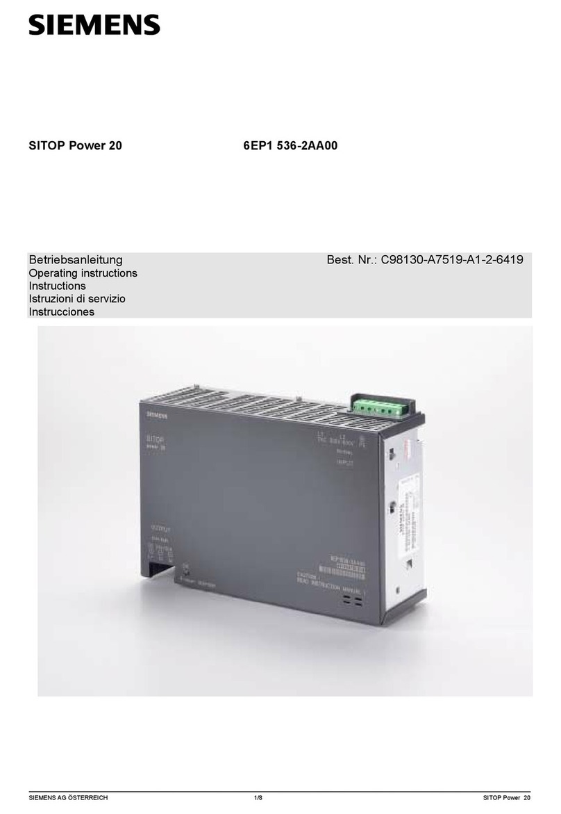
Albalá Ingenieros PSU2000C02 User manual

PSU2000C02
100 - 240 V AC SWITCHING MODE POWER SUPPLY WITH REMOTE
MANAGEMENT FOR UR2000R01 & R02 MOUNTING FRAMES
Version 1.0
Albalá Ingenieros, S.A.
Medea, 4 - 28037 Madrid - Spain
16 December 2014 - © Albalá Ingenieros S.A. - All rights reserved

PSU2000C02

PSU2000C02
100 - 240 V AC SWITCHING MODE POWER SUPPLY WITH REMOTE
MANAGEMENT FOR UR2000R01 & R02 MOUNTING FRAMES
Version 1.0
1. DESCRIPTION ...................................................................................................................... 5
1.1. The TL2000 module family ......................................................................................................... 5
1.2. The PSU2XXX family of power supplies ................................................................................. 5
1.3. The PSU2000C02 ............................................................................................................................ 6
1.4. Features ............................................................................................................................................. 7
1.5. Block diagram .................................................................................................................................. 8
2. SPECIFICATIONS ................................................................................................................. 9
3. INSTALLATION .................................................................................................................. 11
3.1. Initial inspection .......................................................................................................................... 11
3.2. Safety instructions ...................................................................................................................... 11
3.3. Environmental considerations ................................................................................................ 12
3.4. Installing the module in the mounting frame ................................................................... 12
3.5. Proper placement of the mounting frame .......................................................................... 12
3.6. Interconnection ............................................................................................................................ 13
4. OPERATION ...................................................................................................................... 15
4.1. Front panel description .............................................................................................................. 15
4.2. Response to protections ............................................................................................................ 16
4.3. Redundant power supply operation ..................................................................................... 16
4.4. Module remote control and supervision ............................................................................. 18
4.4.1. Details of the PSU2000C02 registers ........................................................................... 19
5. GLOSSARY ........................................................................................................................ 21
6. REGULATIONS .................................................................................................................. 23
7. VERSIONS ......................................................................................................................... 25

PSU2000C02

Albalá Ingenieros | Manual PSU2000C02
1. DESCRIPTION
1.1. The TL2000 module family
The TL2000 family is an advanced, modular design that includes a wide variety of signal
conditioning devices for using in audio and video production, distribution and
broadcasting environments. This modular design provides versatility, ease-of-use and
also a high degree of radio frequency shielding with the goal of avoiding possible
electromagnetic interference problems in hostile environments, such as operation close
to radio frequency transmitters.
1.2. The PSU2XXX family of power supplies
One of the most important aspects of any telecommunications infrastructure
installation is the versatility and the reliability of the power supply network. In order to
provide the greatest degree of versatility for the TL2000 and TL3000 Terminal Lines
Albalá Ingenieros provides switching power supplies for both DC and AC inputs. In
addition, two power supplies, either of the same type or of different types can be
combined within the same mounting frame in order to provide power supply
redundancy. To ensure high reliability both the power supplies and the modules of both
lines include fanless designs and high quality components.
The increase in the cost of real estate together with ever more sophisticated
telecommunications networks require placement of more and more electronics in
smaller and smaller spaces. The TL2000 and TL3000 Terminal Line modules from Albalá
Ingenieros address these requirements and include more and more functionality in the
same space. This increase in the density of both functionality and electronics involves an
increase in the power requirements of the modules and requires both improvement in
the efficiency of the mounting frame power supplies and adequate removal of the heat
generated.
The TL2000 family modules are installed in 19" rack-style, 2 RU mounting frames, model
number UR2000, which has a total of 21 slots. Depending upon the model of the power
supply units to be installed uses one or two slots and whether or not power supply
redundancy is needed, the number of slots available for signal processing modules can
vary from 17 (two power supplies occupying two slots each) to 20 (one single-slot power
supply).
The PSU2XXX family includes a series of power supplies for the UR2000 mounting frame.
Variants of the family are as follows:
• PSU2000C01: 100 - 240V AC / 60 W input switching power supply for the UR2000R01
5

Albalá Ingenieros | Manual PSU2000C02
and UR2000R02 mounting frame.
•PSU2000C02: 100 - 240V AC / 60 W input switching power supply that includes a
communications controller for the UR2000R01 and UR2000R02 mounting frame.
•PSU2100C01: 100 - 240V AC / 100 W input switching power supply that includes a
communications controller for the UR2000R01, UR2000R02 and UR2000R03 mounting
frame.
•PSU2001C01: 20 - 60V DC / 100 W input switching power supply that includes a
communications controller for the UR2000R01, UR2000R02 and UR2000R03 mounting
frame.
•PSU2400C01: 260 - 400V DC / 100 W input switching power supply that includes a
communications controller for the UR2000R01, UR2000R02 and UR2000R03 mounting
frame.
1.3. The PSU2000C02
The PSU2000C02 is a TL2000 Terminal Line module that includes a 100 to 240V AC
input switching power supply capable of powering the modules installed in a U2000
mounting frame.
The PSU2000X family does not uses forced ventilation, increasing reliability and assuring
a low failure rate during years of use. However, the rack where the mounting frame is
installed should include the necessary measures to remove the heat generated by the
modules during operation.
The PSU2000C02 includes remote supervision of the internal temperature of the power
supply, the number of hours of operation and other parameters.
One UR2000 mounting frame can house two PSU2000C02 power supply modules in a
redundant configuration. Also, other PSU2XXX power supply modules can be installed in
a mounting frame along with a PSU2000C02 module. This provides functionality with
both AC and DC input power sources.
6

Albalá Ingenieros | Manual PSU2000C02
1.4. Features
• AC input switching power supply.
• Fits into two slots of UR2000 mounting frames.
•Can be combined with additional AC or DC power supplies within the same mounting
frame to provide redundancy.
• Wide input voltage range.
• Does not need a voltage selector.
• Fanless design provides silent and reliable operation.
• Front panel power-on indicator.
•Module control and supervision can be done remotely when the mounting frame is
equipped with a communications controller module.
• High efficiency.
7

Albalá Ingenieros | Manual PSU2000C02
1.5. Block diagram
8

Albalá Ingenieros | Manual PSU2000C02
2. SPECIFICATIONS
AC power supply input
Connector EN 60320-1-C14
Rated voltage range 100 .. 240VAC ± 10 %
Maximum current 940 .. 420 mA
Rated frequency range 45 .. 65 Hz
Maximum output power 60 W
Maximum input power 68 W
CE marking according to B class EN 55022, EN 60950-1,
EN 61000-3-2 and
ETSI ETS 300 132-1
Hot pluggable Yes
Power on time <2 s
General
Operating temperature range 0 .. 50 °C
Approximate weight 375 g
9

Albalá Ingenieros | Manual PSU2000C02
PSU2000C02
10

Albalá Ingenieros | Manual PSU2000C02
3. INSTALLATION
THE PSU2000C02 MODULE CONTAINS ELECTRONIC DEVICES SENSITIVE TO
ELECTROSTATIC DISCHARGE. Always use antistatic bags clearly identified
with a high degree of shielding for storage and transportation.
3.1. Initial inspection
Make sure that the package has been handled properly during transport. After opening
the package, verify that the PSU2000C02 power supply and the appropriate cable are
inside.
You must notify your Albalá Ingenieros distributor or dealer of any damage or defects
observed.
Follow the instructions in this manual to install this module in the mounting frame.
3.2. Safety instructions
•Dangerous voltages are present inside the power supply. Certain elements
store energy at dangerous voltages. The covers of the power supply should
never be removed. No user-serviceable parts are contained within the power
supply, and in case of malfunction service should be performed by a
technician authorized by Albalá Ingenieros.
•The equipment is a Class I electronic device as per EN60950. The electrical
outlet that supplies this equipment must provide a connection to protective
earth. Keep the electrical output clean and free of humidity. Each AC power
supply is supplied with a certified power cable that should be used to
connect the supply to the outlet.
•The PSU2000C02 does not include an interrupt switch for the electrical
current. The power supply network must include a minimum of a clearly
identified and accessible circuit breaker and a current limiting device in the
immediate vicinity. When a mounting frame has two power supplies
installed both supplies must be turned off in order to cut off the power
supply to the frame.
•The PSU2000C02 module and the mounting frame should always be
installed, maintained, operated and removed by personnel with sufficient
technical qualifications. The equipment should never be placed in damp
areas, near splashing liquid, or in explosive or corrosive atmospheres.
Neither modules nor mounting frames can be used in applications that
11

Albalá Ingenieros | Manual PSU2000C02
could endanger human life.
3.3. Environmental considerations
This symbol indicates that this equipment must be deposited at a collection
point for proper waste treatment once it has reached the end of its useful
life.
3.4. Installing the module in the mounting frame
The following steps should be followed in order to install a PSU2000C02 module in the
mounting frame.
1 - Select two adjacent slots of the mounting frame, preferably the two at the far right.
2 - Insert the module from the front into the selected slot. To ensure proper mounting,
the circuit board should slide into the guides located inside the mounting frame.
Make sure the module's power supply cable is disconnected during this process.
3 - Secure the module in the mounting frame by pressing the two front panel screws.
3.5. Proper placement of the mounting frame
The PSU2000C02 power supply does not use forced ventilation. Therefore the mounting
frame placement must be selected for proper removal of the heat generated by all the
modules installed. Heat extraction can be done with natural convection or with external
forced ventilation.
When forced ventilation is not available for heat extraction then at least one rack unit
(44mm) should be left free both above and below the mounting frame to allow free
circulation of air.
Heat extraction is especially important because the power supply includes automatic
shutdown in case of over temperature, cutting off the power to all the modules installed
in the mounting frame until the temperature falls to a safe level. The behavior of the
supply during over-temperature shutdown is described in the Operation section.
12

Albalá Ingenieros | Manual PSU2000C02
3.6. Interconnection
Once the power supply module is installed in its slot the electrical supply cable can be
connected.
The arrangement of the front panel connector of the PSU2000C02 module is shown in
the following figure.
Front panel of the PSU2000C02
The AC power supply connector on the front of the module is a C6 type as per EN
60320-1. The AC power supply cable used should have a C5 type connector as per EN
60320-1 on one end and the appropriate connector for the mains network on the other.
The EMI capacitors in the EMI filter generate a small current in the protective earth
connection. If too many power supplies are connected to the same mains network the
differential circuit breaker may trip due an excess of current in earth ground. In such
cases the number of power supplies connected to the differential circuit breaker must be
reduced.
13

Albalá Ingenieros | Manual PSU2000C02
PSU2000C02
14

Albalá Ingenieros | Manual PSU2000C02
4. OPERATION
This section describes the significance of the front panel indicators of the PSU2000C02
module and their remote control and monitoring ability.
4.1. Front panel description
The appearance of the front panel and the elements it contains are shown in the
following illustration.
Front panel of the PSU2000C02
The PSU2000C02 power supply does not include a power switch. The supply will begin
operating between one and two seconds after connection to the electrical supply. The
red ON LED lights up to indicate that the power supply is operating.
The ON LED will light up whenever the supply is delivering power. When the
over-temperature protection or any of the other internal protection circuits activate this
LED turns off and the supply stops delivering power.
The ON LED will blink when the temperature of the supply rises, as described in the
following section.
15

Albalá Ingenieros | Manual PSU2000C02
4.2. Response to protections
The power supply includes passive protection against discharges and transient
overvoltages coming from the supply network as well as active protection that will shut
the power down in case of anomalous situations.
The main active protection is for thermal overload (OTP), and features automatic restart.
Shutdown in case of thermal overload avoids damage in cases such as a lack of proper
ventilation. This overtemperature protection will also engage if the power supply
overheats due to degradation or failure of its internal components. Thermal shutdown
engages whenever the temperature of the area dedicated to the rectifiers exceeds 100
°C (the overtemperature threshold). When the power supply reaches this temperature
the output shuts down and stops delivering power to the mounting frame. This will cut
off the power to the mounting frame unless a redundant power supply is installed and
also operating in the mounting frame. The power supply affected by thermal shutdown
will return to operation once the temperature has fallen to a safe level. This time period
depends upon the ambient temperature and is typically around 10 minutes, however it
can be longer when the ambient temperature is elevated and/or little airflow is
available. The shutdown period can be shortened by momentarily disconnecting the
input power supply as the overtemperature shutdown protection will reset as long as
the temperature is below 100 °C when input power is reconnected.
The heat generated by the power supply is proportional to the load. Mounting frames
with varying numbers of modules installed will vary in their thermal behavior, where a
higher number of modules generates more heat.
In addition to thermal overload protection the power supply includes protection against
output short circuits and internal protections that do not use automatic restart because
they may be due to internal failures detected by the supply.
Once thermal overload protection has engaged the ON LED will turn off. This LED will
turn back on once the temperature has fallen by 10 °C. At this point the supply turns
back on and begins powering the mounting frame once again.
When power is disconnected due to activation of the overtemperature protection the
remaining protection circuits are not affected. The supervisory microcontroller remains
powered and the counter for the number of times that the supply has been turned on
and off does not increment.
4.3. Redundant power supply operation
The PSU2000C02 power supply is capable of powering all the modules installed in the
mounting frame. A second power supply can be installed in order to add redundancy to
the power system.
When two power supplies are installed in a mounting frame the total load will be shared
among them, however the proportion of the load supplied by each is not predictable.
Each power supply includes internal circuitry that adjusts the output voltage in order to
balance the power delivered. Management of the power delivered is based upon both
16

Albalá Ingenieros | Manual PSU2000C02
the current requirements and the operating temperature. When the temperature of
each power supply is more or less equal then the power delivered by each is also more or
less equal. Otherwise, whichever supply is hotter will deliver less current and whichever
is cooler will deliver more. Power supplies installed at the ends of the mounting frame
will run cooler because of the additional surface area exposed to the exterior.
When one of the power supplies is an AC input type and the other is a DC input type the
majority of the power will be delivered by the AC input supply. If the AC input supply
fails then the DC input supply will take over without any transient or interruption in the
operation of the mounting frame.
Power supplies with AC inputs do not have the output voltage adjust feature, and
therefore the load is always shared between two such redundant supplies.
The Specifications section of the PSU2000C02 indicates the power capabilities of the
power supply and the Specifications sections of each TL2000 module indicate their
power consumption during operation. This information can be used to calculate the
total power requirements of the mounting frame and determine if the power supply
delivers enough current.
17

Albalá Ingenieros | Manual PSU2000C02
HUB/SWITCH
TL2000
COMMUNICATIONS
CONTROLLER MODULE
OTHER TL2000
MODULES
Ethernet
Ethernet
Ethernet
Ethernet
REMOTE CONTROL UNIT
TLE2001 PSU2000 PSU2000
TLE2001 PSU2000 PSU2000
UR2000 INTERNAL BUS
UR2000 INTERNAL BUS
Module remote control and supervision
4.4. Module remote control and supervision
The PSU2000C02 can optionally be remotely controlled/supervised.
The main function of the communications control module is to interface between a
10/100 Ethernet port and the internal bus of the mounting frame. The following
illustration shows the most common control situations: from a computer or control
panel via Ethernet.
Certain communications control modules provide additional, more advanced functions
such as an SNMP agent, logging of status changes of the modules and a Web interface
for remote control, etc.
Software for simple configuration and supervision with a GUI for multiple modules can
be downloaded from the Albalá Ingenieros website.
18

Albalá Ingenieros | Manual PSU2000C02
The following functions of the PSU2000C02 can be performed remotely:
-Supervision of the power supply status: internal operating temperature, thermal
warning (high temperature), historical maximum temperature, counter for hours of
operation, etc.
4.4.1. Details of the PSU2000C02 registers
The PSU2000C02 module provides control and status registers that can be read and
written by means of specific commands described in the communication control
module user manuals.
The STATUS section parameters are read-only and cannot be modified.
The parameters that can be controlled and supervised remotely for each version of
the firmware are listed below:
In order to perform remote configuration and supervision of the module an optional
TL2000 family remote communications controller must be installed in the mounting
frame.
VERSION 1.X
STATUS
Name add ext msk snmp trap Description
POWER_OFF 0x01 0x01 Y Y Indicates the power supply status
0=OK,1=Fail
TEMP_WARNING 0x01 0x02 Y Y Indicates that actual temperature is over expected range
0=OK,1=Fail
TEMP_FAIL 0x01 0x04 Y Y Indicates that actual temperature is over recommended range
0=OK,1=Fail
ACT_TEMP 0x02 0x7F Y N Displays internal actual temperature
= x ºC
MEAN_TEMP 0x03 0x7F Y N Displays internal mean temperature
= x ºC
MAX_TEMP 0x04 0x7F Y N Displays internal maximun temperature
= x ºC
PON_HOURS 0x05 0xFFFF Y N Displays module power on time
= x h
TOT_MAX_TEMP 0x07 0x7F Y N Displays internal maximun tempertature since first power on
= x ºC
TOT_PON_HOURS 0x08 0xFFFF Y N Displays module power on time since first power on
= x h
TOT_PON_TIMES 0x0A 0xFFFF Y N Displays module power on events since first power on
= x
19

Albalá Ingenieros | Manual PSU2000C02
PSU2000C02
20
Table of contents
