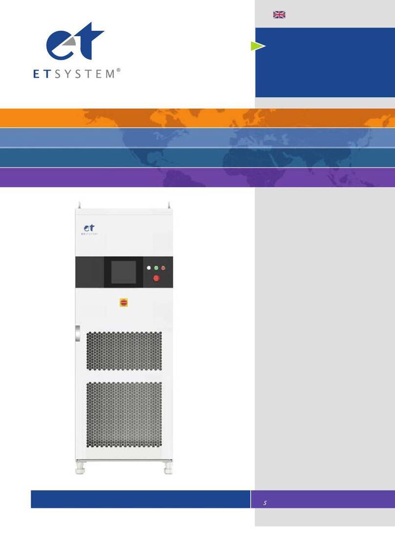
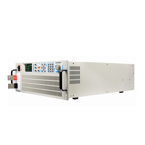
Et system LAB-HP/E Series User manual

ET System electronic GmbH
Telefon 06205 3948-0
Fax 06205 37560
Hauptstraße 119-121
68804 Altlußheim
www.et-system.de
C
LAB-HP/E

Software version: V15
November 2016

Table of Contents
Info & Contact Addresses ............................................................................................................................................1
Technical Specifications ..............................................................................................................................................2
Input Specifications ........................................................................................................................................................2
Output Specifications .....................................................................................................................................................3
AI Interface.....................................................................................................................................................................4
RS 232.............................................................................................................................................................................4
RS 485.............................................................................................................................................................................4
EMC and Safety standards .............................................................................................................................................4
Ambient Conditions........................................................................................................................................................4
Important Safety Instructions .....................................................................................................................................5
Initial Operation .............................................................................................................................................................5
Unpacking.......................................................................................................................................................................5
Setting Up.......................................................................................................................................................................5
Visual Inspection ............................................................................................................................................................5
Mains Operation ............................................................................................................................................................5
Intended Use ..................................................................................................................................................................5
Drawing ......................................................................................................................................................................6
Functional Description ................................................................................................................................................7
General Settings..........................................................................................................................................................8
Configuration..................................................................................................................................................................8
Voltage Settings ..........................................................................................................................................................9
Ulimit and Ilimit ...................................................................................................................................................................9
OVP (Over Voltage Protection).......................................................................................................................................9
AI-Type ...........................................................................................................................................................................9
Description of the different LEDs ...................................................................................................................................9
Universal interface ...................................................................................................................................................10
Commands ...................................................................................................................................................................10
Format .....................................................................................................................................................................10
Instruction Set .........................................................................................................................................................10
Quick view of commands ........................................................................................................................................10
Detailed description of commands..........................................................................................................................10
Response String .......................................................................................................................................................16
Ext. Control: Computer.............................................................................................................................................. 18
GPIB..............................................................................................................................................................................18
Status Word.............................................................................................................................................................19
ESR-Register - Event-Status-Register.......................................................................................................................19
RS232 Interface ............................................................................................................................................................20
Interface Reconfiguration........................................................................................................................................21
RS485 Interface ............................................................................................................................................................21
Interface Reconfiguration........................................................................................................................................22
Ext. Control: AI Interface ..........................................................................................................................................23
Pin Assignment AI Interface .........................................................................................................................................23
Analog Input .................................................................................................................................................................24
Set Point U (USet)......................................................................................................................................................24
Set Point I (ISet).........................................................................................................................................................24
Set Point OVP (UOVP) ................................................................................................................................................24
Analog Output ..............................................................................................................................................................24
Monitor Set Point U (Umon PRESET) .........................................................................................................................24
Monitor Set Point I (Imon PRESET) ............................................................................................................................24
Monitor Output Voltage (UIstmon Real value) ...........................................................................................................24
Monitor Output Current (IIstmon Real value).............................................................................................................25

Digital Input ................................................................................................................................................................. 25
Activation (Ext. Control).......................................................................................................................................... 25
Blocking (Standby) .................................................................................................................................................. 25
Digital Output .............................................................................................................................................................. 25
Blocking (Standby) .................................................................................................................................................. 25
Const. Voltage mode (CV)............................................................................................................................................ 25
Error............................................................................................................................................................................. 25
Ext. Control: Ethernet (LAN)...................................................................................................................................... 26
Determinating the IP using the Device Installer by LANTRONIX ................................................................................. 26
Controlling the device via Telnet ................................................................................................................................. 27
TELNET Connection with REALTERM ........................................................................................................................... 27
Ext. Control: USB....................................................................................................................................................... 28
Interface Reconfiguration....................................................................................................................................... 28
Sense Mode .............................................................................................................................................................. 29
Load connection without Sensor Conductor ............................................................................................................... 29
Load Connection without Sensor conductor ............................................................................................................... 29
Load connection with Sensor Conductor .................................................................................................................... 29
General Information for sensing ................................................................................................................................. 30
Warning indtructions for using Relays to the Load Draft ............................................................................................ 30
Appendix .................................................................................................................................................................. 31
Equivalent leakage current measurement according to VDE 0701 ............................................................................. 31
ET-System Rippel Measurment Specification .............................................................................................................. 32
Notes ........................................................................................................................................................................ 34


Info & Contact Addresses
ET System electronic GmbH 1
INFO & CONTACT ADDRESSES
ET System electronic GmbH was founded in 1986 in the heart of the Rhine-Neckar-Triangle. As a subsidiary of a
leading electricity utility group, the company quickly took on a leading role in the area of laboratory power electronics
and associated electrical measurement. The existing know-how in power technologies in the 90s gave rise to the
“Power Solutions” product division as a strong extension of the historical “Test & Measurement” range.
Since 1997, we have been working successfully as an independent, privately held company with customers in all lines
of business from industry, medical care, railway technology and automotive electronics.
By means of our high vertical range of manufacture and our ever expanding development division we can fast and
flexibly adjust to our customers’requirements. Necessary approvals such as CSA, UL, VDE, TÜV etc. are flexibly carried
out by qualified personnel. The approval procedures are performed within the scope of development planning and
thus do not negatively impact the start of manufacturing. Permanent manufacturing control through accredited
laboratories and an ISO 9001 compliant quality management system guarantee a constant high-level series-
production quality.
We offer repairs and adjustment for units outside of our warranty period. Please contact your local distributor for
further information:
Place of Business: Altlußheim, Germany
VAT Identification Number: DE 144 285 482
Register Court: Mannheim, Germany
Register Number: HRB 421186
Managing Director: Dipl.-Ing. Eric Keim
Sales Manager: Roland Kosmowski
Development Leader: Hermann Amtsberg
Germany
Great Britain
France
Korea
ET System electronic GmbH
Hauptstraße 119-121
68804 Altlußheim
Germany
ET Power Systems Ltd.
The Bridge Business Centre
Chesterfield
S41 9FG
United Kingdom
ET Systeme electronic
4 rue Ampère
38080 L’Isle d’Abeau
France
ET System electronic
Korea Corporation
DaeHyeon Techno World 1203
19,Ojengongeup-gil,
Uiwang-si,
Gyeonggi-do 437-753
Republic of Korea
Phone: +49 (0) 6205 39480
Fax: +49 (0) 6205 37560
Phone: +44 (0) 1246 452909
Fax: +44 (0) 1246 452942
Phone: +33 (0) 474 278234
Fax: +33 (0) 474 278068
Phone: +82 (0) 31 451 4491
Fax : +82 (0) 31 453 4459
em@il: info@et-system.de
web: www.et-system.de
em@il: sales@etps.co.uk
web: www.et-system.com
em@il: info@et-system.fr
web: www.et-system.fr

Technical Specifications
2 ET System electronic GmbH
TECHNICAL SPECIFICATIONS
INPUT SPECIFICATION:
Device Power 5kW 10kW 15kW 20kW 30kW 45kW 60kW
Connection
Input 1P/230
Input 3P/200
Input 3P/209
Input 3P/400
Input 3P/440
Input 3P/480
Maxallowed non
symetry
(3P-Systeme)
Input current 1,2
1P/230 Modell
33 A eff
X 14 X 14 X 14 X 14 X 14 X 14
Input current 1,2
3P/200 Modell
25 A eff 50 A eff 74 A eff 99 A eff 148 A eff 221 A eff 295 A eff
Input current 1,2
3P/208 Modell
23 A eff 46 A eff 69 A eff 92 A eff 138 A eff 207 A eff 276 A eff
Input current 1,2
3P/400 Modell
11,5 A eff 22,9 A eff 34,4 A eff 45,8 A eff 68,7 A eff 103,1 A eff 137,5 A eff
Input current 1,2
3P/440 Modell
11 A eff 21 A eff 32,5 A eff 42 A eff 63,5 A eff 95 A eff 127 A eff
Input current 1,2
3P/480 Modell
10 A eff 19,5 A eff 30 A eff 39 A eff 58 A eff 87 A eff 117 A eff
Nominal current
Internal Fuse
3P/400 Modelle
15 A 30 A 45 A 60 A 90 A 135 A 180 A
Recommended Supply
breaker 3P/400 Model
(value and curve)
16A
Type D/K
32A
Type D/K
63A
Type D/K
63A
Type D/K
80A
Type D/K
120A
Type D/K
150A
Type D/K
Leakage current
cos phi
Harmonic content 3
Efficiency Type
50Hz = 72% / 100Hz = 2% / 150Hz = 0,9% / 200Hz = 0,1% / 250Hz = 11% / 350Hz = 0,6%
94%
<153 A
<229 A
3 x440VAC (396-484VAC 47-63Hz)
3 x480VAC(432-528VAC47-63Hz)
< 3%
<305
<35 mA
>0,7
Inrusch
transientcurrent 2
<25 A
<51 A
<76 A
<102 A
3 x400VAC(360-440VAC47-63Hz)
LAB/HP/E
3 Leitungen (1P+N+E) / 5 Leitungen (3P+N+E)
1 x230VAC(207-253VAC47-63Hz)
3 x200VAC(180-220VAC47-63Hz
3 x208VAC(187-229VAC47-63Hz)
1 For nominal current and voltage
2 For nominal input voltage
3 Total harmonic distortion input current ([%] I in)
4 250A is the maximum possible current for an 5kW Unit
5 If the ripple is not specified, maximum allowed ripple is 0,2% of F.S.
6 The measurement of the peak peak ripple is strongly dependent of the measurement setup
7 The given accuracy is also all interfaces valid
9 Higher number is possible, ask manufacturer
11 The ripple measurment methode of ET-System is specified at application note „ET Ripple-Spec. (Page 32)
12 The ripple specification is reservation to change on the part of manufacturer
13 Device is at the moment only available with highspeed output (Low output cap.)
14 Not as standard Unit available

Technical Specifications
ET System electronic GmbH 3
OUTPUT SPECIFICATION:
Static Regulation
Line Regulation Voltage
Line Regulating Current
Load Regulation Voltage
Load Regulation Current
Dynamic Response Time
@Load Step 10 - 90%
Output Voltage [V] 15 20 25 35 40 45 70 80 100 150 300 600 800 1000 1200 1500
HP/E 5KW Unit [A] x250 200 150 125 120 75 65 50 35 17 8,5 6,5 5 4,2 3,3
HP/E 10KW Unit [A] x500 x350 250 250 175 130 100 75 40 17 13 10 8 6,6
HP/E 15KW Unit [A] x750 x x 375 x x 195 150 100 50 25 19 15 12 9,9
Voltage ripple (p-p)
20MHz
40 12 80 12 80 12 80 12 140 12 140 12 140 12 140 12 140 12 900 12 900 12 900 12 1000 12 1200 2500 2500
Voltage ripple (p-p)
300KHz
15 12 35 12 35 12 35 12 60 12 60 12 60 12 60 12 60 12 400 12 400 12 400 12 700 12 800 1500 1500
Voltage ripple (rms)5mV
20MHz
15 35 35 35 60 60 60 60 60 400 400 400 400 400 400 500
Voltage ripple (rms)5mV
300KHz
10 12 25 12 25 12 25 12 40 12 40 12 40 12 40 12 40 12 300 12 300 12 300 12 300 12 300 300 400
Current ripple (p-p)
Current ripple (rms)
Primary / Sekundary
DC - Output/ Earth
Primary / Earth
Rise time full Load 13 6 ms 6 ms 6 ms 6ms 12 ms 12 ms 12 ms 20 ms 20 ms 20 ms 20 ms 20 ms 40 ms 40 ms 40 ms 6 ms
Rise time no Load 13 5 ms 5 ms 5 ms 5 ms 10 ms 10 ms 10 ms 10 ms 10 ms 10 ms 10 ms 10 ms 10 ms 20 ms 20 ms 5 ms
Fall time full Load 13 15 ms 15 ms 15 ms 15 ms 20 ms 20 ms 20 ms 20 ms 20 ms 40 ms 40 ms 50 ms 60 ms 80 ms 100 ms 25 ms
Fall time no Load
Rel. Accuracy ±[%]7
Voltage [V] 0,25 0,038 0,050 0,063 0,088 0,100 0,113 0,175 0,200 0,250 0,375 0,750 1,500 2,000 2,500 3,000 3,750
Current [A] 0,4 1,000 1,000 0,800 0,580 0,500 0,480 0,288 0,260 0,200 0,140 0,068 0,034 0,026 0,020 0,017 0,013
Voltage [V] 0,5 0,075 0,100 0,125 0,175 0,200 0,225 0,350 0,400 0,500 0,750 1,500 3,000 4,000 5,000 6,000 7,500
Max. Sens Voltage over
nominal Voltage 7
Max. Sens Voltage inside the
normal Voltage range7
Resolution Voltage
Display
Voltage setting resolution
Resolution Current
Display
Current setting resolution
OVP
UI-Modus
100V - 999,9V
000.0
15V - 99,99V
00.00
10A - 99,99A
00.00
100A - 999,9A
000.0
1.000A - 9.999A
0000
Over Voltage Protection: is adjustable between 0% and 120% of Voltage full range
Voltage and Current operation mode: Voltage and current are setable
Device Function
OTP
Over Temperature Protection: if the internal heat sink tempearatury is go above 90°C
the divice will automaticaly shut down
Resolution
<0,4 % of F.S.
Ripple and Noise 11
Accuracy
3.000VAC
500VDC
2.000VDC
2.150VDC
Isolation
5 s unter 50VDC
Output speed
Relative Accuracy for Sens operation (worst case) [%]
1.000V - 1.500V
0000
0A - 9,999A
0.000
5% of F.S. (if higher voltage is needed ask manufacturer)
±1% of F.S.
OCP
Over Current Protection: is realised by the current set point.
The output current can not go over the set value
Regulation
± 0,1% of F.S.
± 0,02% F.S.
± 0,02% F.S.
± 0,05 % F.S. ± 2mV
± 0,05% F.S. ± 20mA
< 3ms
Other combinations of Voltage and Current also possible, ask the Manufakturer
Basic calculation of possible combinations are:
Pout = Vout x Iout / Pmax for one Unit 90KW / Cmax = 250A each 5KW
Output Current
<0,5 % of F.S.

4 ET System electronic GmbH
IMPORTANT SAFETY INSTRUCTIONS

Important Safety Instructions
ET System electronic GmbH 5
Please read this manual thoroughly before putting the device
into operation. Pay regard to the following safety instructions
and keep this manual nearby for future purpose.
This operating manual is based on the state of technology at the time of printing. However, it is possible that despite
regular control and correction, the present document contains printing errors or deficiencies. ET System electronic
GmbH assumes no liability for any technical, printing or translational errors within this manual.
INITIAL OPERATION
UNPACKING
Please make sure that the shipping carton and the packaging is free of damage. If external damage is found, it is
important to record the type of damage. Please keep the original packaging to ensure the device is adequately
protected in case it needs to be transported in the future or claims for compensation need to be asserted.
SETTING UP
To avoid electric shocks and product failure, the device should be installed in a temperature and humidity controlled
indoor environment. The ambient temperature must not exceed 50 °C. The device must never be exposed to liquids or
extreme humidity.
VISUAL INSPECTION
The unit must be examined immediately for defects or damages in transit. Damages caused during transport may be
loose or broken control knobs and bent or broken connectors. Do not use the device if any physical damage is
apparent. Please inform the carriers and a representative of ET System electronic immediately.
MAINS OPERATION
Make sure to verify the model number and voltage stated on the nameplate. Damages due to wrong power feed are
not covered by guarantee conditions.
The unit must only be operated when connected directly to the
mains. To avoid damage, do not connect the unit to
isolating transfo rm ers, auto-transformers, magnetic current
limiters or similar devices.
INTENDED USE
The device corresponds to protection class I and has a galvanic isolation between the input and the output circuit. The
device must be grounded on the input side, since the grounding ensures protection against contact. In the case of
locally variable devices, the earth is connected to the device by means of a cold-plug connector, and the ground is
connected to the screw terminal provided for locally-variable devices (screw contacts at the grid input). In the case of
devices with high leakage current (marking on the device), the existing grounding bolt must additionally be connected
to the domestic installation earth. For compliance with the EMC and safety regulations (CE, approvals), the device may
only be operated with PE connected. The device may only be operated by trained personnel and in accordance with
the instructions for use. Typical fields of application are laboratories, industry and service engineering. Applications
which can lead to injuries or death in the event of a fault in the device are not permitted.

Important Safety Instructions
6 ET System electronic GmbH

Important Safety Instructions
ET System electronic GmbH 7
FUNCTIONAL DESCRIPTION
THE FOLLOWING BLOCK DIAGRAM GIVES INFORMATION ABOUT THE VARIOUS ADJUSTMENT OPTIONS.
UI-Mode
Unit is oprated with current and voltage limitation.

General Settings
8 ET System electronic GmbH
GENERAL SETTINGS
CONFIGURATION
The front panel has three buttons to change the parameters for voltage, current and OVP (Over Voltage Protection).
Since the device is operated in UI mode only, the set values for voltage and current will be transferred directly to the
switching regulator. There is no additional digital control. The following picture displays the control panel and control
structure of the device.

Voltage Settings
ET System electronic GmbH 9
VOLTAGE SETTINGS
ULIMIT AND ILIMIT
Ulimit limits the maximum output voltage. The output voltage is limited to the selected value, irrespective of the values
that have been set at the front panel or at one of the interfaces. The adjustment range is 0 V up to the maximum
rated voltage of the device.
Ilimit limits the maximum output current. The output current is limited to the selected value, irrespective of the values
that have been set at the front panel or at one of the interfaces. The adjustment range is 0 A up to the maximum
rated current of the device.
These settings can only be changed at the display and they apply to all interfaces.
OVP (OVER VOLTAGE PROTECTION)
The output is shut immediately if the output voltage exceeds the selected value. The display indicates this status with
the word ‚OVP‘. To reset this error, push the button Standby. The OVP value applies to the front panel operation.
There may apply different values for the AI-interface and the digital interface. The digital interface is initialized with
the value which has been adjusted on the front panel. The adjustment range is 0 V up to the maximum rated voltage
of the device + 20%.
AI-TYPE
This feature adjusts the voltage levels of analog input signals and analog output signals. Selectable ranges are 0-5 V
and 0-10 V.
DESCRIPTION OF THE DIFFERENT LEDS
CV
Constant Voltage
PV
Preset Voltage
CC
Constant Current
PC
Preset Current
CP
Over Voltage Protection
Remote
Local or Remote Operation
Standby
Standby Status

Universal interface
10 ET System electronic GmbH
UNIVERSAL INTERFACE
All interfaces of the digital interface are equal. There is no shift between the interfaces. For example, the first
command can be issued via the IEEE interface while the second command can be issued via the RS232 interface. The
return values will be sent from that interface the command was issued from.
COMMANDS
Communication is based on an ASCII protocol. The following chapters describe how to write a command and give an
overview over the commands.
Format
A command consists of the command word, a parameter (if necessary) and a terminator. The character for the
terminator is Carriage Return <CR> or Line Feed <LF>.
Character
ASCII
Dec value
Hex value
Carriage Return
<CR>
13
0d
Line Fee
<LF>
10
0a
If the command contains a <DEL> or <ESC> character, it will not be processed. Therefore, a command can be cancelled
while entering. Though, a terminator (<CR> or <LF>) is necessary.
Character
ASCII
Dec value
Hex value
Escape
<ESC>
27
1b
Delete
<DEL>
127
7f
Commands are not case sensitive and may be mixed up. Therefore, the effect of the following commands is the same:
GTL, Gtl, gTL. Decimal places are optional and separated by a full stop ‘.‘ . The number of decimal places is not limited.
Therefore, the effect of the following commands is the same: UA,10, UA,10.0, UA,10.000000000, UA,0010,
UA,010.0000
The number of decimal places to be analyzed depends on parameter and unit type. It corresponds to the number of
decimal places, a command without a parameter would return.
Example: Evaluation of decimal places of power supplies maximum output voltage and current
Range 100V- 999,9V 1000V- 1500V
Voltage 000.0 0000
Range 0A- 9,999A 10A- 99,99A 100A - 999,9A 1000A- 9999A
Current 0.000 00.00 000.0 0000
15V - 99,99V
00.00
Example: LAB/HP/E 580 (80VDC; 65A) digital interface reading Voltage 0.00 –80.00V; Current 0.00 –65.00A
Optional, after a numerical value, a letter may be added to indicate the unit. However, this letter will not be analyzed.
Example: Attached letter as unit
UA,10.0 V Resets output voltage to 10 V
UA,10.0 m Caution! The ‚m‘ will not be evaluated, output voltage here is also 10 V
Example: A valid command with corresponding hex values
U
A
,
1
0
.
2
<CR>
55 h
41 h
2 ch
31 h
30 h
2 eh
32 h
0 dh
Example: Adjustment of output voltage 10 V/5 A (full command sequence)
OVP,100 adjusts OVP to 100 V
UA,10 adjusts output voltage to 10 V
IA,5 current limiting 5 A
SB,R output enabled

Universal interface
ET System electronic GmbH 11
Instruction Set
The IEEE-488.2 standard demands several basic commands. Some commands may occur twice for compatibility
reasons (once in the ETS version and once in the (old) IEEE-488.2 version). The following syntax is used to describe the
commands:
[]
Square brackets
optional parameter
<>
Angle bracket
numerical value
{}
Curly bracket
selection list
|
Vertical line
separator within selection list
Example
GTR[,{0|1|2}] means that the command GTR can be used with or without parameters. If a parameter exists, it has to be 1, 2 or 3. Valid
commands are: GTR GTR,1 GTR,2 GTR,3
IA[,<imax>] means that the command IA can be used either with or without parameters. If a parameter exists, it has to be a numerical
value.
Quick view of commands
Command
Description
Result
CLS* or CLS
Clear Status
Deletes the status byte
DCL
Device Clear
Initialization data reset
GTL
Go To Local
Activates front panel operation
GTR[,{0|1|2}]
Go To Remote
Activates digital interface operation
IA[,<imax>]
Set Imax
Adjusts current limiting
ID or *IDN?
Identification
Displays identification string
LLO
Local Lockout
Deactivates LOCAL button
LIMI
Limit Ia
Reads maximum adjustable current limitation
LIMU
Limit Ua
Reads maximum adjustable voltage limitation
MI[,<Nr>]
Measure Ia
Measures present output current
MU[,<Nr>]
Measure Ua
Measures present output voltage
*OPT?
Optional Identification Query
Displays units current hardware/software version
OVP[,<Uovp>]
Overvoltage Protection
Adjusts over voltage protection
PCx[,<baud>,<parity>,
<data bits>,<stop bits>,
<handshake>,<echo>,
<timeout>]
Program
Communication
Adjusts the interfaces
RI or *RST
Reset Instrument
Resets hardware (no return value)
SB[,{S|R|1|0}]
Standby
Enables/blocks the output
SS or *PDU
Save Setup
Saves previously made channel and interface parameter adjustments (no return
value)
STATUS
Status
Query of the units’ status (return values in binary format) (also see following
table)
STB or *STB?
Interface Status
Displays the interface status.
UA[,<ua>]
Set Ua
Adjusts output voltage (if there are no parameters, present set point is
displayed)
Detailed description of commands
CLS* or CLS - Clear Status
This command deletes the status byte. It affects only the status byte of the interface, the command was sent from. No
return value. For detailed description of the status byte see the different interface chapters.
DCL - Device Clear
This command resets the initialization data. No return value.
Caution: Interface parameters are also reset!

Universal interface
12 ET System electronic GmbH
GTL - Go To Local
This command activates front panel operation. If ‚Local Lockout‘ (LLO) was activated before, it will also be reset. No
return value.
GTR[,{0|1|2}] - Go To Remote
This command activates digital interface operation. The optional parameter affects the future behavior of the unit
after switch on. Setting is saved permanently. No return value.
Optional parameter 0 = Deactivates automatic remote operation
The command GTR must be entered to activate the unit’s remote operation mode. This mode is useful if the unit shall be operated
manually and at the same time, measurement values shall be read out via the digital interface.
Optional parameter 1 = Activates remote operation on first addressing
Unit switches to remote operation when receiving a command via digital interface. The only exception is the GTL command, which
switches the unit to local mode.
Optional parameter 2 = Activates remote operation immediately after switch on
After the unit was switched on, remote mode is immediately activated. Front panel operation is deactivated.
IA[,<imax>] - Set Imax
This command adjusts current limiting. Entering the command without parameters displays the set value. If the set
value is higher than the maximum current of the unit, the range-error-bit within the ESR register of the interface is set.
The present set value remains unchanged. If the set value is higher than the Ilimit value, which was adjusted by the
user’s settings, but lower than the maximum current of the unit, the current is limited to the Ilimit value. No error
message.
Example: 300 A unit, Ilimit adjusted to 200 A via configuration menu
GTR
Remote operation
OVP,200
Over voltage protection 200 V
UA,10
Output voltage 10 V
IA,100
Output current 100 A
SB,R
Output open
IA,400
Output current 400 A, this command is ignored, because the current is higher than the maximum current of the device.
„Rangeerror“ is set within the status byte.
IA,250
Output current 250 A, since the output current was limited to 200 A via configuration menu, current limiting is set to 200
A. Error bit is not set.
IA
Query of the adjusted current.
IA,200.0A
Unit answers: Ilimit = 200,0 A
ID or IDN? - Identification
This command displays the identification string. Return value: <ID-String>.
LLO - Local Lockout
This command deactivates the Local button. Unit cannot be switched to local mode by holding the button Standby.
No return value.

Universal interface
ET System electronic GmbH 13
LIMI - Limit Ia
With this command the user can read the maximum adjustable current limiting.
Example: 300A unit, Ilimit was adjusted to 200 A via configuration menu
LIMI
Query of maximum adjustable current
LIMI,200.0A
Unit answers: Ilimit = 200,0 A
LIMU - Limit Ua
Reads maximum adjustable voltage limitation. This command requests the previously defined maximum output
voltage.
Example: 300 V unit was adjusted to 200 V via configuration menu
LIMU
Query of maximum adjustable current
LIMU,200.0V
Unit answers: Ulimit = 200.0 V
MI[,<Nr>] - Measure Ia
This command measures the present output current.
Example:LAB/HP/E 15100 (100VDC; 150A)
GTR
Remote operation
OVP,140
Over voltage protection 140 V
UA,100
Output voltage 100 V
IA,50
Output current 50 A
SB,R
Output open
MI
Measures present output current
MI,50.0A
Unit answers: 50,0 A
MU[,<Nr>] - Measure Ua
This command shows the measurement value of the present output voltage.
Example:LAB/HP/E 15100 (100VDC; 150A)
GTR
Remote operation mode
OVP,140
Over voltage protection 140 V
UA,10
Output voltage 10 V
IA,1
Output current 1 A
SB,R
Output open
MU
Measures present output voltage
MU,10.0V
Unit answers: 10,0 V

Universal interface
14 ET System electronic GmbH
*OPT? - Optional Identification Query
This command does an optional identification query, which means it displays the software version.
Example:
*OPT?
Query of version number
08.06.2012 V42
Unit answers: Version 42 vom 08.06.2012
OVP[,<Uovp>] - Over Voltage Protection
This command adjusts the over voltage protection. Entering the command without parameter displays the present set
point. If the set point is higher than a maximum of 1.2 x voltage of the unit, the range error bit within the ESR register
of the interface is set. The present set point remains unchanged.
Example:
GTR
Remote operation mode
OVP,200
Over voltage protection 200 V
UA,100
Output voltage 100 V
IA,10
Output current 10 A
SB,R
Output open
PCx[,<baud>,<parity>,<data bits>,<stop bits>,<handshake>,<echo>,<timeout>] - Program Communication
This command adjusts the interfaces. The LAB/HP/E has a maximum of 3 digital interfaces (x = 1, 2 or 3). The
corresponding commands are PC1, PC2 or PC3. Type and number of parameters depend on the type of interface.
Currently there are no settings available for GPIB and LAN. Entering the command without parameter displays present
interface parameters.
Parameter
Function
<baud>
Baud rate in bps
<parity>
Data parity
O = Odd = Uneven parity
E = Even = Even parity
N = None = No parity bit
<data bits>
Number of data bits
<stop bits>
Number of stop bits
<handshake>
Handshake
H = Hardware
S = Software
N = None (no handshake)
<echo>
Character echo
E = Echo = echo on
N = None = echo off
<timeout>
Timeout in ms when switching between sending and receiving (RS485 only)
Allowed parameters for RS232 interface:
PCx,<baud>,<parity>,<data bits>,<stop bits>,<handshake>,<echo>
Parameter
Function
Baud:
1200, 2400, 4800, 9600, 14400, 19200, 38400, 57600, 62500, 115200
Parity:
O, E, N
Data bits:
7, 8
Stop bits
1, 2
Handshake:
H, S, N
Echo:
E, N
This manual suits for next models
3
Table of contents
Other Et system Power Supply manuals
