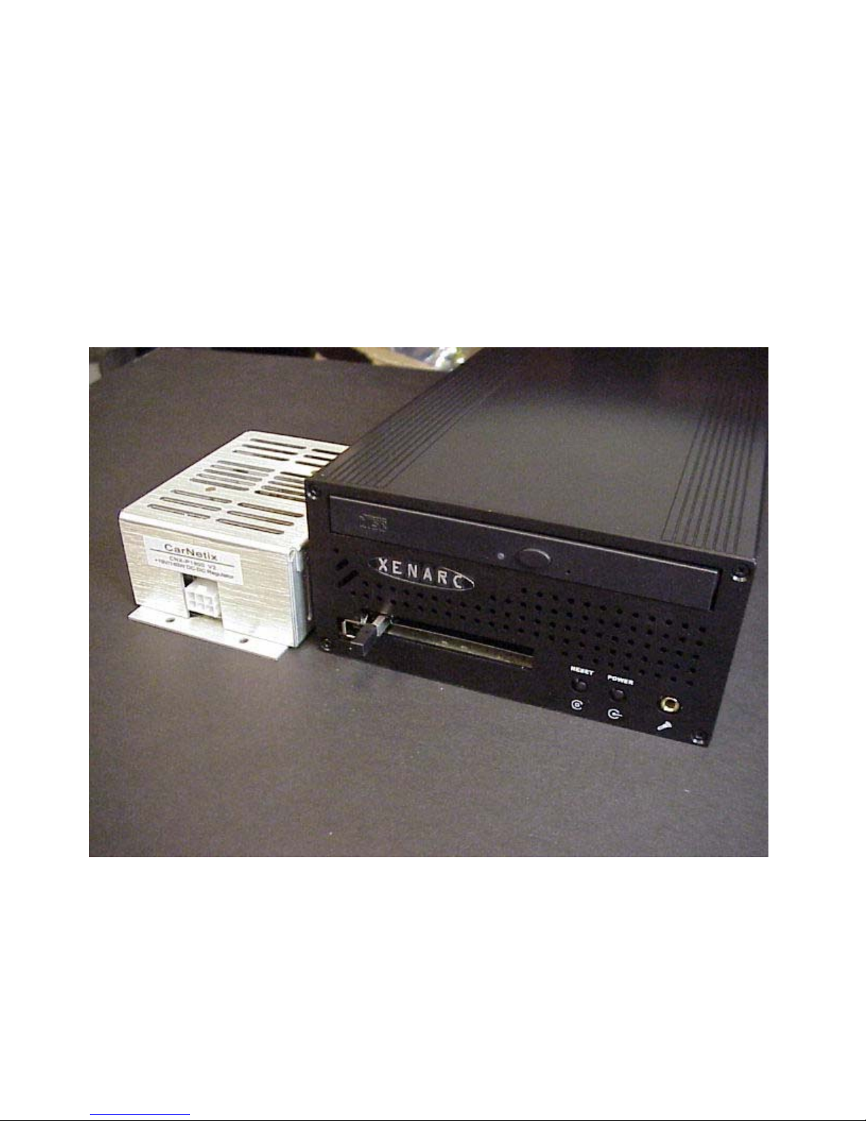
CarNetix PSU-PC19 V2.0 Installation Manual
Table of Contents
1.0 PSU-PC19 Introduction..................................................................................................................4
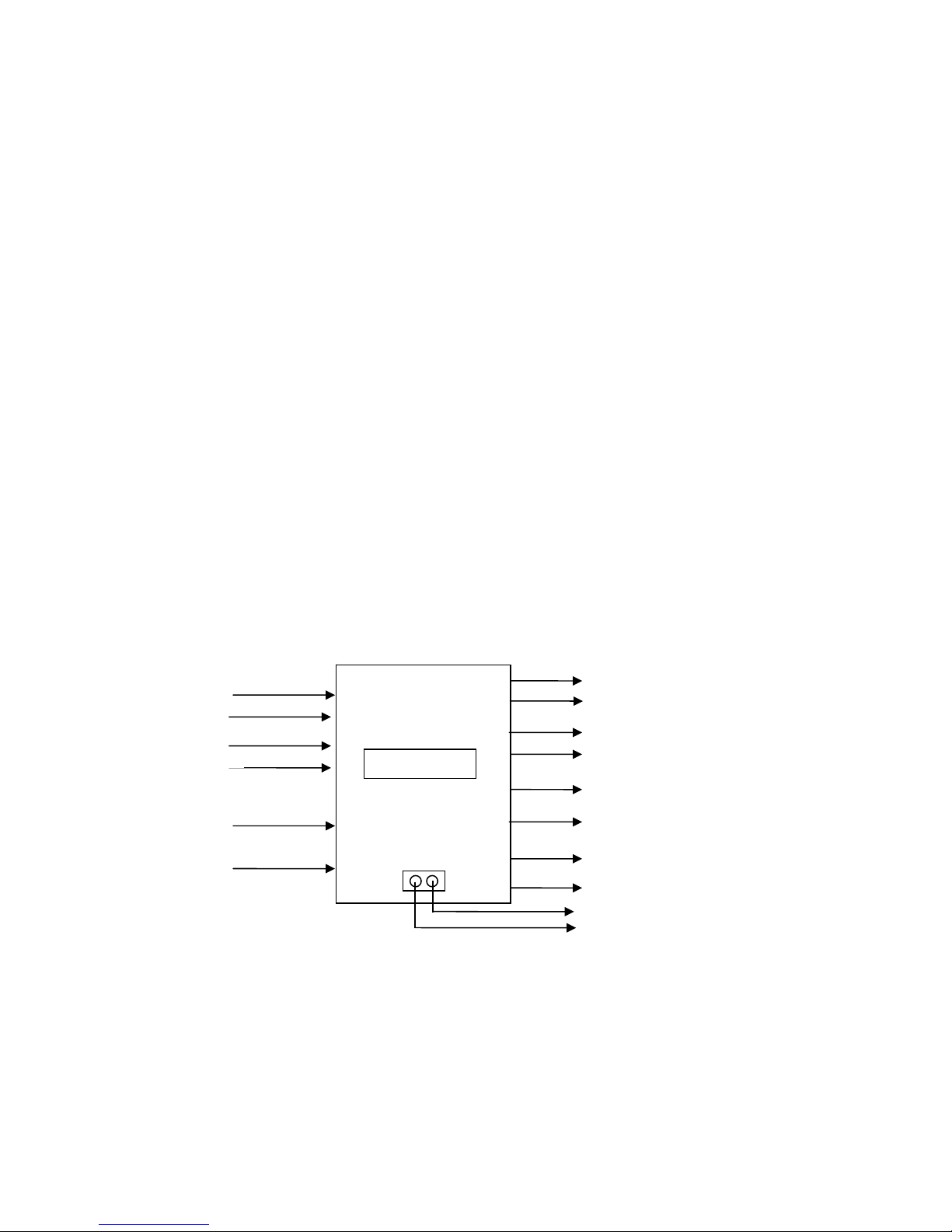
1.1 Introduction................................................................................................................................. 4
1.2 Primary Output Power................................................................................................................ 7
1.3 Secondary Power Output............................................................................................................7
Using the Secondary Output for +5V devices.............................................................................. 7
Using the Secondary Output for +12V devices............................................................................ 7
1.4 Startup/Shutdown Controller (SSC) Overview........................................................................... 8
2.0 Installing the PSU-PC19.................................................................................................................9
2.1 Before You Begin....................................................................................................................... 9
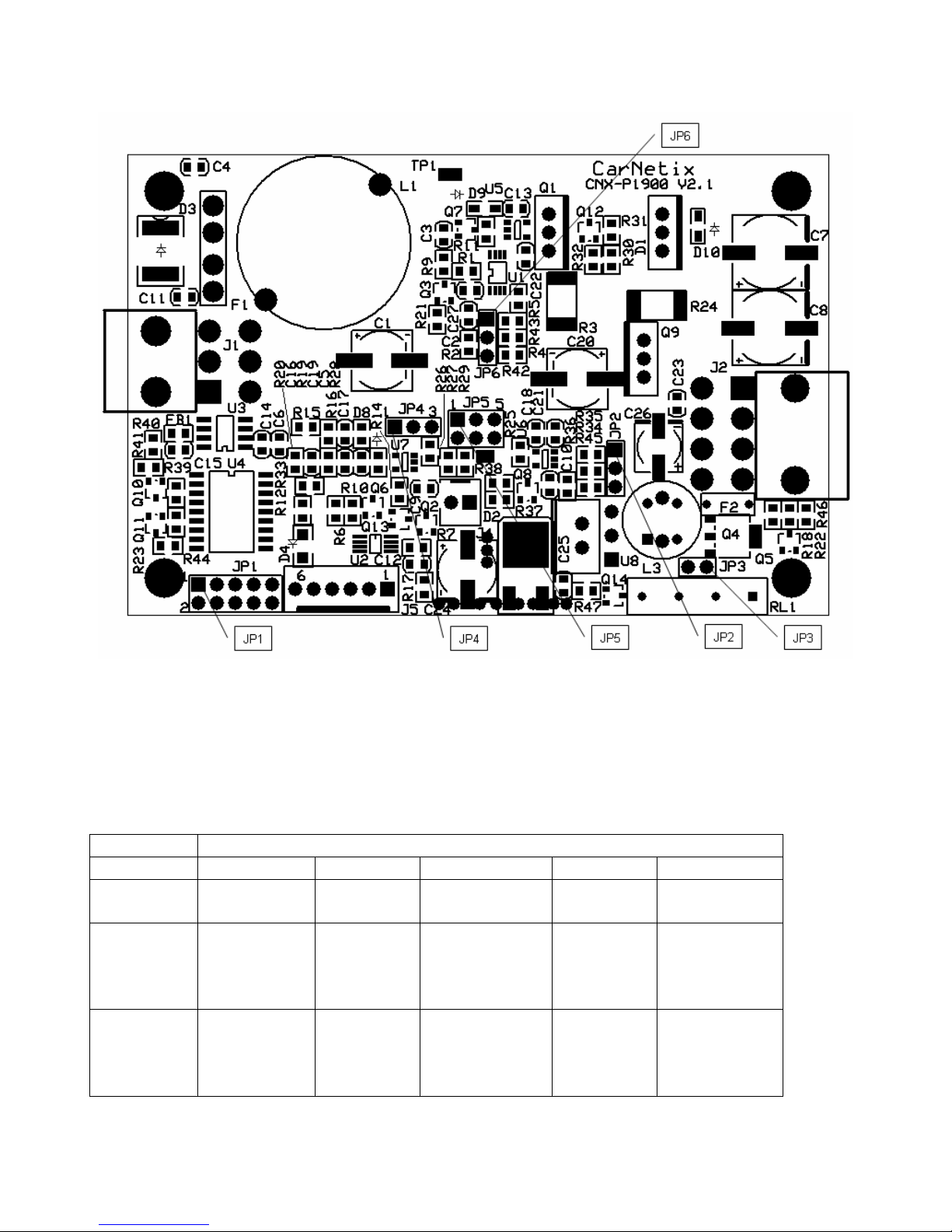
2.2 Setting the Jumpers.....................................................................................................................9
2.2.1 Setting JP1 Jumpers........................................................................................................... 10
2.2.2 Setting JP2 (Secondary Output Voltage)........................................................................... 11
2.2.3 Using JP3 ACPI Relay Output ..........................................................................................12
2.2.4 Setting JP4 (Secondary Output Control) ...........................................................................12
2.2.5 Setting JP5 (Secondary Power Input Select) ..................................................................... 13
2.2.6 Setting JP6 (Primary Output Voltage Selection)...............................................................14
2.3 Connecting the Wiring..............................................................................................................14
2.3 Connecting the Wiring..............................................................................................................15
2.4 Optionally Connecting the Xenarc LCD Screen.......................................................................18
3.0 Using the Pulse Start Feature........................................................................................................ 20
3.1 Pulse Start Connections............................................................................................................20
3.2 Pulse Start Operation................................................................................................................20
3.2.1 What is a pulse?.................................................................................................................20
3.2.2 Starting the PSU with a pulse............................................................................................20
3.2.3 Stopping the PSU with a pulse ..........................................................................................21
3.2.4 Prolonging the Shutdown Delay State...............................................................................21
3.2.5 Shutting down the PSU with double pulses....................................................................... 21
3.2.6 Ignition Override................................................................................................................21
4.0 Startup/Shutdown Controller........................................................................................................22
4.1 Hibernate/Standby Operation ...................................................................................................22
4.2 SSC Operation States................................................................................................................ 22
4.2.1 Idle State............................................................................................................................ 22
4.2.2 RunDelay State.................................................................................................................. 22
4.2.3 Bootup Lockout State ........................................................................................................ 23
4.2.4 Run State............................................................................................................................ 23
4.2.5 Shutdown Delay State........................................................................................................23
4.2.6 Shutdown Sequence State..................................................................................................23
4.2.7 Forced Shutdown State......................................................................................................24
4.3 Fault Indicator LEDS................................................................................................................ 24
5.0 Conditions of Use ......................................................................................................................... 27
- 2 -