Albion 1051-1 ROVER User manual

BACKER ROD INSTALLATION MACHINE
Model 1051-1 ROVER
OR VISIT WWW.ALBIONENG.COM
QUESTIONS? CALL 856.235.6688

INTRODUCTION
Dear ustomer
Thank you for choosing an Albion Engineering Co. product!
The Rover you have purchased was designed to help you
accomplish large scale caulking task . This patented
one-of-a-kind invention began with an individual in the
caulking and sealing trade looking for a way to install
backer rod on large out of town projects. When day
laborers and helpers weren't available or showing up late to
the job site, the necessity for making backer rod installation
a one man operation was needed. The Roveremerged
from his workshop and evolvedinto tool on
site because the energy saved installing backer rod could
be better spent on joint preparation, mixing, dispensing,
and tooling the caulking.
“A more consistent backer rod depth can directly translate
into a more consistent caulking bead. With improved
craftsmanship and faster completion rates you can be hired
more frequently and have a reputation for quality in your
caulking and sealing trade." -inventor
e
Albion Engineering is a third-generation company internation-
technologies. Albion supports multiple industries with
innovative, high-quality dispensing tools and accessories for
the most demanding applications.
More information on our products and services is available via:
Web: www.albioneng.com
Email: service@albioneng.com
Phone: 856-235-6688
Catalog and Handbook 333.
Backer Rod Rover Features
• Quickly sets polyethylene foam backer rod in saw cuts
and expansion joints
• Fast one-man, walk behind operation
• Reduce job site fatigue and labor cost
• Pack joints from 1/8"- / " wide by changing insertion
wheels
•epth adjustable up to 3/4" deep
•Heavy duty all-steel construction
• High visibility orange nish
•
• Compatible with most major manufacture s of spooled
backer rod
• Can be customized for spec c applications
•
page 2
Part Number

20
1
C
2
4
5
6
78
9
10
11
12
13
14
15
A
B
3
16
16
17
ALLOW 1/8”
CLEARANCE
BETWEEN
SPOOL &
RETAINER
BACKER ROD
18
19
A, B, C: Couplers
1. Handle bar assembly
2. Lower handle assembly
3. Rear insertion wheel adjustment T-handle
4. Rover body
5. Insertion wheel rail
6. Insertion wheel screw x 3
7. Insertion wheel x 3 p/n 1059-H1x
8. Tube bracket
9. Hose clamps
10. Backer rod guide tube
11. Front insertion wheel adjustment T-handle
12. Vertical support
13. Horizontal support
14. Spool/frame linchpin
15. 1/4-20 bolts
16. Support arms x 2
17. Outer spool spring collars x 2
18. Spool axle
19. Inner spool retainers x 2
20. Backer rod spool (not included)
21. Hard plastic storage/travel case (not shown)
PARTSLIST
PRESENTATION
Fig. 1
page 3

ASSEMBLING
Unpacking
• Remove all contents from shipping container and remove
all parts from packing material. The front and rear insertion
wheel T-handles (3 & 11) can be used as lifting points for
the Rover.
• The front and rear T-handles control the insertion wheel
depth by turning clockwise and counter clockwise.
• Place rover on flat surface making sure all insertion wheels
are in up position and all four tires are in contact with
surface.
•Reference all parts to figure 1
Assembly (see figure1)
Transport and storage
page 4
• Starting with the spool assembly, begin by unfolding and
inserting the linchpin (14) into an upright position.
• Next, thread vertical support (12) into coupler (A). Turn
clockwise until hand tight.
• Slide spool axle (18) into the opening at one end of a
support arm (16) followed by an inner spool retainer (19),
backer rod spool (20), and another inner spool retainer (19)
then slide spool axle (18) through the opposite support arm
(16). Make sure the long end of the inner spool retainer (19)
are facing the backer rod spool (20) and that the thumb
screws are not in contact of the backer rod spool.
• Make sure backer rod spool (20) is dispensing backer
rod from the front top side, and it has a clear path to the
guide tube.
• Install both of the outer spool spring collars (17) onto each
end of the spool axle (18). Center the backer rod spool (20)
on the spool axle (18) and tighten thumb screws on the
inner spool retainers (19). Allow for some clearance
between the inner spool retainers (19) and backer rod
spool (20). For large
•Note: backer rod spool must rotate freely and
independently from the spool axle.
• Install the lower handle assembly (2) by turning clockwise
into coupler (B) until hand tight.
• Install handle bar assembly (1) into the coupler (C) and
turn clockwise until hand tight.
• On the final rotation the handle bar must be positioned
parallel to rover body.
• Always store the Rover with insertion wheels in up
position
• Dismantle the handle and carriage assemblies before
transporting
• Secure the equipment in storage container to avoid
damage or accidents when transporting.
• Store the Rover and backer rod in a dry, secure indoor
location.
Technical Data (fully assembled)
•Shipping weight:86lbs.
• Length 56"
• Width 24" - with standard rod
•38" wide with rod extension kit
1074-1 (sold separately)
• Height 44"
• Maximum insertion wheel depth 3/4"
• Operation: Manual

ADJUSTMENTS AND TECHNIQUE
page 5
• Place Rover in a 45° position (as shown) and
confirm all 3 insertion wheels spin freely. (see Figure 2)
• Confirm backer rod is passing through the guide tube
with very little resistance.
•To change insertion wheels place the Rover in 45° or
sideways position. Rotate front and rear wheel adjustment
T-handles all the way down so that they are fully exposed.
Remove axles using 1/2”wrenches or socket. Remove the
insertion wheel hubs (with bearings inside) with a 3/32"
hex wrench. Attach hubs tightly to new wheels and
reassemble to Rover, being careful not to over tighten.
•Confirm that wheels spin freely before putting Rover
back into service.
See pg. 2 for additional
wheel sizes.
Fig. 2
BEGINNING OF JOINT
TOP OF CONCRETE
“BACKER ROD TAIL”
TOP OF CONCRETE
1/8”
1/8”
1/2”
• Backer rod guide tube should be
approximately 1/8" from top of
concrete and at least 1/2”from the front
insertion wheel.
(see gure 4A)
• When operating, the front insertion wheel
should be approximately 1/8”inside the
joint. (see gure 4A)
• The rear insertion wheel should be
adjusted to nal desired depth.
Max. depth 3/4”(see gure 4)
Fig. 4 Fig. 4A
MAX. DEPTH 3/4”

ADJUSTMENTS AND TECHNIQUE
page 6
• As backer rod volume on the spool decreases remove the
linchpin and re-secure in the forward position to maintain a
straight path into the guide tube. (see figure 6)
Fig. 6
• Use an Albion 640-series backer rod insertion
tool (sold separately) for entry and exit points
made with the Rover. (see figure 7)
Fig. 7
• Ensure backer rod guide tube is centered with the
insertion wheels. (see gure 3)
Fig. 3
BOTTOM
OF ROVER
BACKER ROD GUIDE TUBE
FRONT INSERTION WHEEL
LOOSEN HOSE
CLAMPS TO ADJUST
OR CHANGE GUIDE TUBE
LINCH PIN
MAINTAIN
STRAIGHT
PATH

OPERATING INSTRUCTIONS
Dene the work zone
•Clear the work area before operating the Rover.
• Be aware of your surroundings. Use cones and caution
tape in work zones.
• Wear high visibility clothing, gloves, and steel toe boots
• Never work alone, always ensure there is another person
close at hand.
• Work in good weather conditions on dry concrete when-
ever possible.
• Try to seal joints same day backer rod is installed to
prevent recontamination.
Before installing backer rod
• Joint preparation is critical.
• Chase out the saw cuts to clear joints of any dirt and debris.
• Machine cut joint prole to engineer specications.
• Clear and remove all construction debris from joint and
surrounding surfaces.
• Read and understand sealant manufacturer’s
requirements.
Start rolling in backer rod
• Place fully assembled Rover over the beginning of a
joint.
• Thread backer rod into the guide tube and tilt Rover into
45 degree position resting on the handle then pull
approximately 18" of extra backer rod through the exit
end of the guide tube to create a "tail". (see figure 2)
page 7
• Place the Rover in the upright position and turn both
insertion wheel T-handles clockwise and simultaneously
until front insertion wheel is approximately 1/8" inside the
joint.
• Turn the rear T-handle an additional 3 revolutions and push
Rover forward a few feet. Inspect backer rod depth and fine
tune the rear T-handle adjustment for ideal depth.
(see figure 4)
• Push the Rover forward, starting slow to let the backer rod
spool gradually begin to rotate. Increase forward speed to a
steady walk.
• When exiting a joint,press down on the handle while
pushing the rover forward. This will bring the insertion
wheels out of the joint. Keep dispensing backer rod until
there is enough extra to complete the joint while having
enough to start the next joint.Then cut the backer rod.
• At these start and stop points use an Albion 640-series
insertion tool and tamping blade to roll in the "tails".
(see figure 7)
• When moving from one joint to the next, press down on
handle so the Rover rides on the rear tires to avoid direct
contact of the insertion wheels to the concrete surface.
• Keep Rover in a 45° position resting on the handle when
not in use or raise insertion wheels up to avoid damage.

TROUBLESHOOTING
Backer rod is breaking during operation
•Note:Not all backer rod is spooledcorrectly. Finding a
spool of backer rod without overlap and tangles is essential
for smooth operations. When using 1/4" backer rod a 2,000'
spool can be more user friendly than the 3,200' and 4,000'
footspools.
•Check backer rod spoolfor tangles and overlap. To correct,
place Rover handle into wind and remove backerrod until
tangles and overlaps are chased out. Carefullyrewindbacker
rod back onto spool.
• Do not push Rover too fast. Start out slow and increase toa
normal walking speed. This becomes increasingly important
as the backer rod spool diameter decreases.
•It iscritical the joints are cleanand ready for sealant before
backer rod is applied. Any rocks, sand, concrete dust, or
debris can eect the performance of this machine. Joint
preparation and cleaning must be done prior tobacker rod
installation.
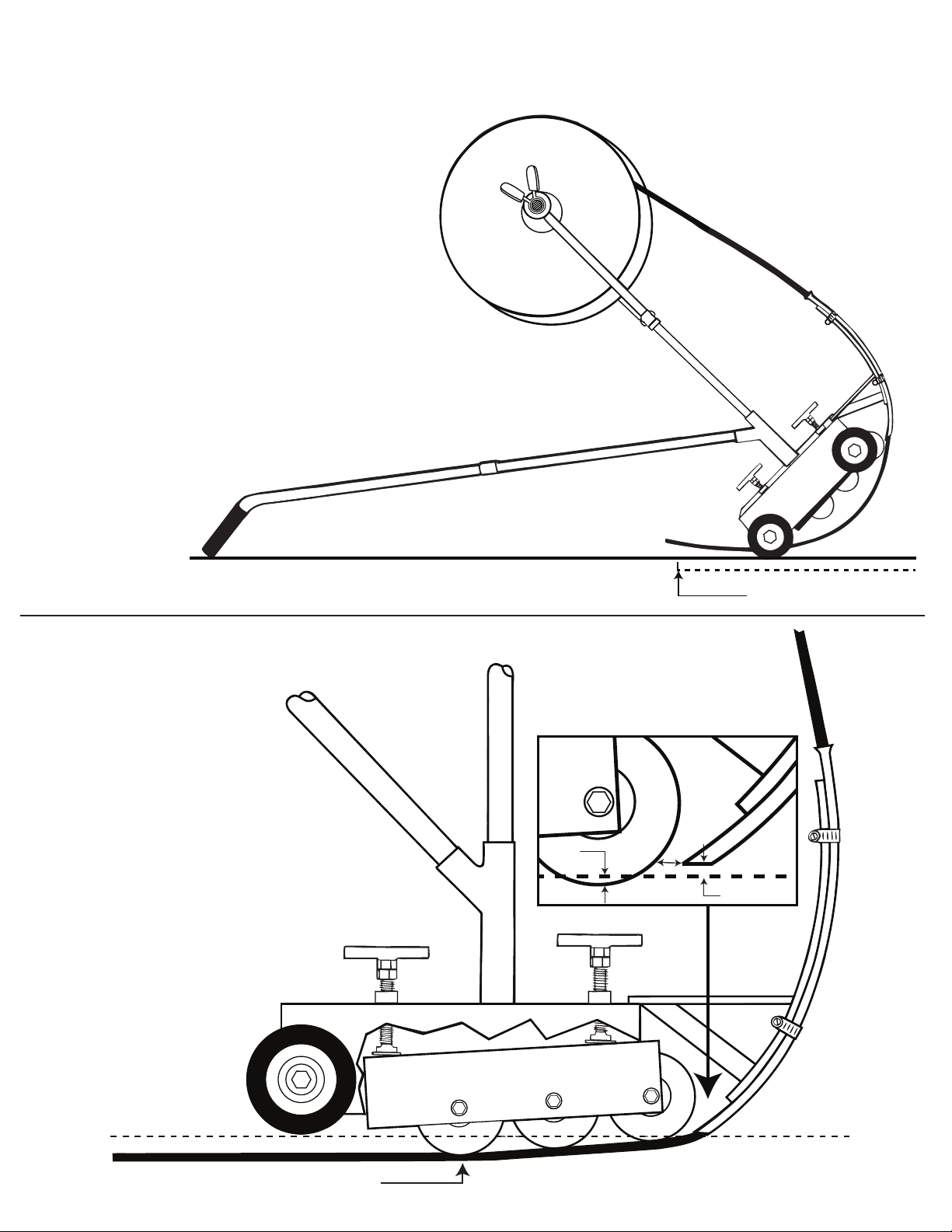
•Move the spool carriage to its forward position to maintain a
smooth entry angle into the entry point of guide tube.
(see gure 6)
•Check for clearance between spool retainers and backer rod
spool. The spool axle should not be spinning with the backer
rod spool. Spool must rotate freely without friction.
•Ensure backer rod passes freely through guide tube
without friction.
•Check backer rod guide tube for burr on exit end.
Backer rod is too largefor guide tube
Backer rod is punctured or cut at entry points of the joint
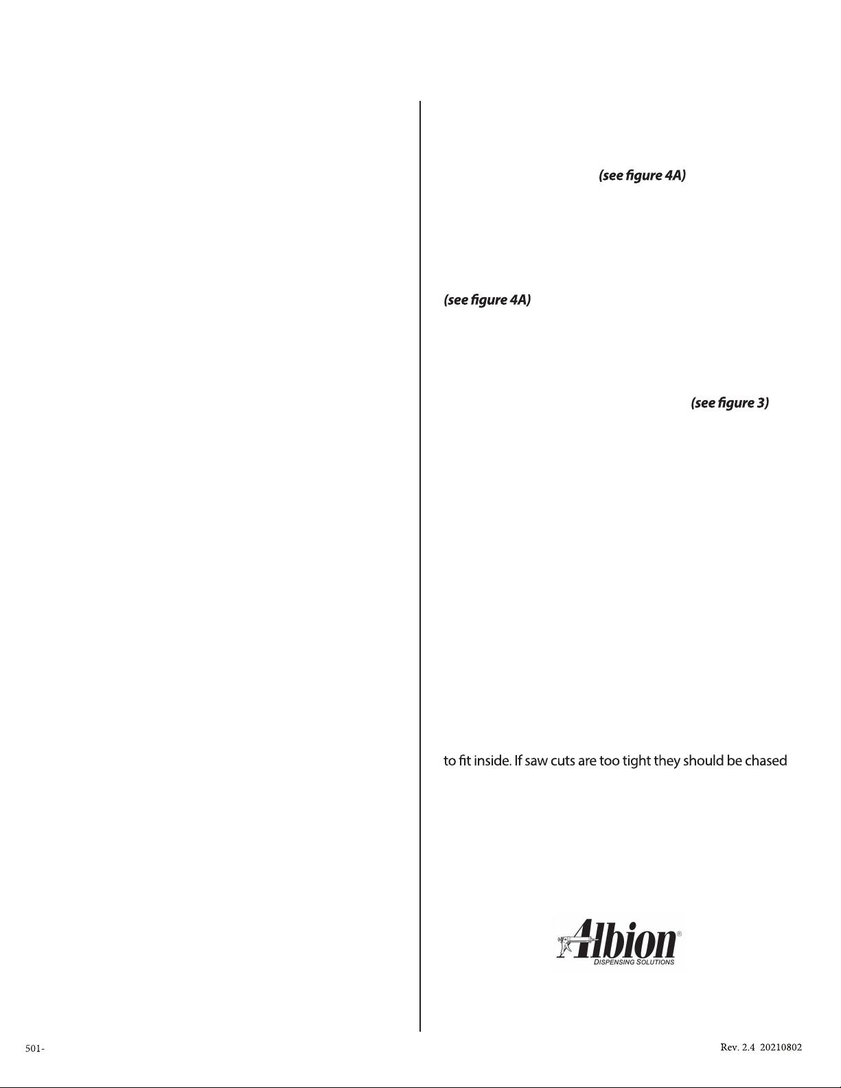
• Adjust front insertion wheel upwards. Approximately 1/8"
shouldbe inside the joint.
Backer rod does not roll into joint when Rover is
pushed forward
• Make sure front insertion wheel is not set too deep.
• Wiggle handle slightly while pushing Rover forward to
help start backer rod into the joint.
•Checkbacker rod guide tube alignment.
• Step on the backer rod "tail" while pushing Rover forward.
Backer rod is too shallow in the joint
• Adjust the rearinsertion wheel down.
• For extremely tight joints or joints requiring adeep sealant
bed, asecond passwithout dispensing additional backer rod
may be necessary. Setting the insertions wheelsdeeper for a
second dry pass can provide an acceptable depth.
• For custom applications requiring backer rod depth deeper
than 3/4" contact Albion Engineering.
• Make sure saw cutiswide enough for the insertion wheels
out and re-cut to proper width.
• The joint can be silted with debris and may require
additionalcleaning.
page 8
OR VISIT WWW.ALBIONENG.COM
QUESTIONS? CALL 856.235.6688
•Make sure backer rod size matches the guide tube and
insertion wheelsizes.
• Backerrod can swellslightly when stored in extreme heat or
become elliptical during the forming process. In most cases it
is faster to replace the backerrod instead of changing the
guide tube.
179
Table of contents