manuals.online logo
Brands
  1. Home
  2. •
  3. Brands
  4. •
  5. Albion
  6. •
  7. Control Unit
  8. •
  9. Albion TMV3 Installation instructions

Albion TMV3 Installation instructions

Albion Valves (UK) Ltd
www.albionvalvesuk.com
Email: [email protected]
Tel: 01226 729900
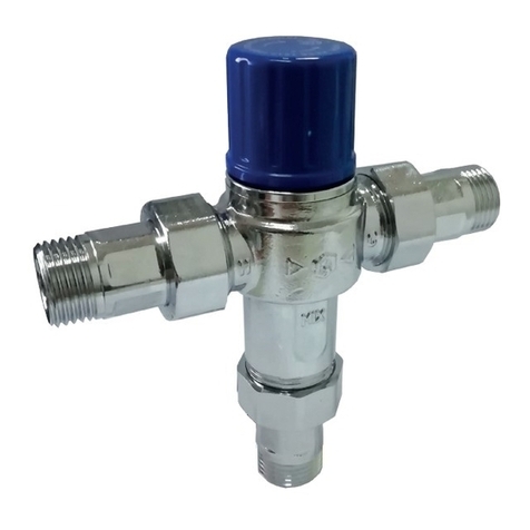
TMV3 ART 33 Screwed Rev 1
TMV3 Installation &
Operating Manual
ART 33
Screwed Thermostatic
Mixing Valve
2
TMV3 ART 33 Screwed Rev 1
Contents
1. Introduction
2. Approvals
3. TechnicalSpecication
4. Product Dimensions
5. Conditions of normal use (TMV3)
6. Installation and Assembly
7. Commissioning & Adjustment
8. Maintenance & In-Service Testing
9. TMV Cleaning Instructions
10. Warranty
1. Introduction
• Thevalvescoveredbytheseinstructionshavebeentestedandcertiedasbeingin 
 compliancewithBS7942:2000andNHSEstatesModelEngineeringSpecication 
 DHHTM04-01SpecicationD08.
• Valves operating outside the requirements of these standards are not covered by the TMV3
Scheme and are not guaranteed to operate as type 3 valves.
• The National Health Service Estates (NHSE) Health Guidance Note (HGN) makes reference
to three types of valve:
• Type 1
  o Havingbothowcontrolanduseradjustmentofmixedwatertemperature
• Type 2
  o Havingowcontrolandpre-setmixedwatertemperature
• Type 3
  o Withoutowcontrolandwithpre-settemperature
• The installer should be aware of his duty of care and responsibility in ensuring that
compliance with regulation is adhered to. The valve is not guaranteed to function
 correctlytotheTMV3specicationunlessitisinstalledandusedinaccordancewiththese
instructions.
• TheAlbionART33thermostaticmixingvalveisavailableinsizes1/2”&3/4”,itisintended
 tobettedintoapplicationswherethereliablecontrolofhotwatertemperatureis 
necessary to prevent scalding.
• Intheeventofcold-watersupplyfailure,theproductwillshutoffthehotwatersupply.
3
TMV3 ART 33 Screwed Rev 1
2. Approvals
• TheAlbionART33iscertiedundertheTMV3schemeandhasbeenindependentlytested
bytherecognizedtestlaboratoryNSFWalesandisaWaterRegulationsAdvisoryScheme
(WRAS)approvedproductandthelistedintheWaterFittingsandMaterialDirectory.
3. Technical Specication
FactoryTemperatureSetting 42°C
Temperature Adjustment Range 30°C – 48°C
MixTemperatureStability +/-2°C
Cold Water Supply Temperature 5°C – 25°C
Hot Water Supply Temperature 55°C – 65°C
Temperature Differential (Hot Inlet – Outlet) 12°C
Supply Pressure Imbalance 2:1
MaximumStaticPressure 10 Bar
4. Product Dimensions
Dimensions are given for ART 33 in Table 1
Table 1
Model DN Size B C D E
ART 33 1/2” 59 114 126 50.9
ART 33 3/4” 61 135 137 50.9
4
TMV3 ART 33 Screwed Rev 1
5. Conditions of Normal Use (TMV3)
Water Regulations
•  Thethermostaticmixingvalvemustbeinstalledinaccordancewiththeregulationsofthe
 localwatercompanyandtheWaterSupply(WaterFittings)Regulations1999.
Operating Pressure Range High Pressure Low Pressure
MaximumStaticPressure(Bar) 10 10
Hot & Cold Pressure (Bar) 1.0 – 5.0 0.2 – 1.0
Hot Supply Temperature (°C) 55 – 65 55 – 65
Cold Supply Temperature (°C) 5 – 20 5 – 20
MixWaterTemperature(°C) Maximum46 Maximum46
Temperature Differential (°C) 12 12
• ThermostaticMixingValvesaretemperaturesensitivedevicesandmustnotbesubjected
 toextremetemperatures,eitherhotorcold,inuseforinstallation.
• Valves operating outside these conditions of use cannot be guaranteed to operate
as TMV 3 valves.
• Designations of Use
  HP-B/S/W/T44
  LP-B/S/W
6. Installation & Assembly
5
TMV3 ART 33 Screwed Rev 1
Assembly Procedure
• Thevalvebodyisclearlymarkedwith“C”andablueindicatorforcoldand“H”andared
indicator for hot.
• The use of sealing compounds is not recommended.
• Beforeinstallation,thehotandcold-waterinletofthemixingvalvemustbeclearofdebris.
the valve must be correctly connected to the respective supplies.
• Isolationvalvesmustbettedadjacenttothevalveinlet.APressurereducingvalve(PRV)
 mustbettedifdeemednecessary.
• Check the main valve assembly bores are free of debris and the end sealing faces are
clean.
• Checkthetwotailpiecesandconrmtheyarecompletewithunionnutsandcompression
nuts with olives.
• Insertthesealingwasherintotheinletsandoutletandscrewtheinletandoutletttings
 ontothevalvebody,takingcarenottoovertighten.
• Removethecompressionnutsandolivesfromthetailpieces.Locatetheinletlterscreens
and insert them into the bore of the tailpieces up to the shoulder.
• Assemble the valve to the pipe work and ensure the hot and cold-water pipes have full
 penetrationintothetailpieces.Thecompressionttingssuppliedallowfordirect 
connection to BS 22mm OD tube or BS 15mm OD tube.
6
TMV3 ART 33 Screwed Rev 1
• Tighten the compression nuts ensuring that the end of the pipe remains in contact with the
 lterelement.
• After installation check carefully for leaks.
• Thevalvemustalwaysbettedinalocationwhereitisaccessibleforbothtestand 
maintenance.
Exploded View of ART 33
7. Commissioning & Adjustment
•  TheAlbionART33thermostaticmixingvalveissuppliedfactorypre-setat41--43°C. 
 However,installationconditionswilldictate,thattheproductbeadjustedonsite.
•  Priortocommencingcommissioning,thefollowingchecksshouldbecarriedout
• The designation of the TMV matches the application.
• The supply pressures and temperatures are within the operating range of the valve.
 • Isolatingvalvesaretted.
• The supply temperatures are within the range permitted for the valve and by
guidance information on the prevention of legionella etc.
•  Ifalltheseconditionsaremet,proceedtosetthetemperatureasbelow:-
• Remove the protective cap on top of the valve.
  • Back-outthenutusingahexagonwrench:
   o Toincreasethetemperature,turnclockwise
   o Todecreasethetemperature,turnanti-clockwise
7
TMV3 ART 33 Screwed Rev 1
• Temperature is in accordance with the valve application as per the table below: -
HP (1.0 – 5.0 Bar)
High Pressure
LP (0.2 – 1 Bar)
Low Pressure Application Maximum
Temperature (°C)
HP-B LP-B Bidet 38
HP-S LP-S Shower 41
HP-W LP-W Wash Basin 41
HP-T44 Bath 44
• When the valve has been installed with the correct conditions of use it is advised that
the valve is subjected to normal operation prior to the commissioning at the application
temperature. Operate the valve from full cold to full hot at least three times by removing
 theblueplasticcapandusingahexagonwrenchtoadjust.
• With the valve at the full cold position bring the valve to the correct application
 temperaturebyturningthenutclockwise.Ifthevalveexceedsthistemperature,returnthe 
 valvetothefullcoldcondition,andresetittothecorrecttemperature+0-2°C.Donotseta 
valve with a lowered temperature as this will not provide consistent operation.
• After adjustment replace the cap to lock the valve in position and prevent tampering.
• Commissioning Test sequence
 •Afteradjustingthetemperatureofthemixedwaterinaccordancewiththevalveapplication.
• Record the temperature of the hot and cold-water supplies.
• Recordthetemperatureofthemixedwateratthelargestdraw-offowrate.
• Recordthetemperatureofthemixedwateratasmallerdraw-offowrate,whichshallbe 
measured.
• Isolatethecold-watersupplytothemixingvalveandmonitorthemixedwatertemperature 
 recordingthemaximumtemperatureachievedandthenalstabilizedtemperature.
• Recordtheequipment,thermometeretc.usedforthemeasurements.
•  Thenalstabilisedtemperaturemustnotexceedthevaluesinthetablebelowandmust 
 neverexceed46°C:-
Application Max Temperature °C
Bidet 40
Shower 43
Wash Basin 43
Bath 46 (note 1)
8
TMV3 ART 33 Screwed Rev 1
Note 1
•  46°Cisthemaximummixedwatertemperaturefromthebathtap.Themaximum 
temperature takes account of the allowable temperature tolerances inherent in
 thermostaticmixingvalvesandtemperaturelossesinmetalbaths.Itisnotasafebathing
temperature for adults or children.
• The British Burns Association recommends 37 to 37.5°C as a comfortable bathing
 temperatureforchildren.InpremisescoveredbytheCareStandardsAct2000,  
 themaximummixedwateroutlettemperatureis43°C.
8. Maintenance & In-Service Testing
• The purpose of in-service testing is to regularly monitor and record the performance of the
 thermostaticmixingvalve.Deteriorationinperformancecanindicatetheneedforservice
 workonthevalveand/orwatersupply.
• Carry out the test sequence using the same or equivalent equipment used for
commissioning the valve.
•  Ifthemixedwatertemperaturehaschangedsignicantlyfromtheprevioustestresults
 (e.g.>1°C),recordthechangeandbeforere-adjustingthemixedwatertemperaturecarry
out the following checks;
 • Allin-lineorintegralltersareclean.
• Any in-line or integral non-return valves or other anti-back siphonage devices are in
good working condition.
• Any isolation valves are fully open.
•  Withanacceptablemixedwatertemperature,completethetestsequenceaspersection7
of this document.
•  Intheabsenceofanyotherinstructionorguidance,itisrecommendedthatIn-Service
 Testsarecarriedoutasperthetablebelow.Ifthetemperatureisoutsideoftheexpected
range it will be necessary to remove and clean the valve in accordance with the
instructions in the table below: -
Temperature Variation (°C) Comment Service Frequency (Weeks)
+/-1°C N/A 24 – 28 Weeks
+/-1°C–2°C In either one period 24 – 28 Weeks
+/-1°C–2°C In both periods 18 – 21 Weeks
+/-Exceed2°C In either period 18 – 21 Weeks
• Ifthereisaresidualowduringthecommissioningorbi-annualverication(cold 
water supply isolation test) then this is acceptable providing the temperature of the water
 seepingfromthevalveisnomorethan2°Cabovethedesignatedmaximummixedwater
9
TMV3 ART 33 Screwed Rev 1
outlet temperature setting of the valve.
• Ifawatersupplyisfedbygravitythenthesupplypressureshouldbeveriedtoensurethe
conditions of use are appropriate for the valve.
• Thettingofisolationvalvesisrequiredascloseasispracticabletothewatersupply 
 inletsofthethermostaticmixingvalve.
• Temperaturereadingsshouldbetakenatthenormalowrateafterallowingthesystem
 tostabilize.Thesensingpartofthethermometerprobemustbefullysubmergedin 
the water that is to be tested. Any TMV that has been adjusted or serviced must be re-
commissioned and re-tested in accordance with the manufacturer’s instructions.
• Intheabsenceofanyotherinstructionorguidance,itisrecommendedthatIn-service 
Tests are carried out once every 6 months as a minimum.
9. TMV Cleaning Instructions
• Most domestic water supplies contain calcium which will separate out when the water is
heated in a system. The degree and speed of scaling may vary depending on factors such
 aswaterowrates,systemdesign,thehardnessofthewaterandthetemperatureto 
which the water is heated.
•  Depositsofscalemayovertimeforminthevalve,particularlyatthehotinlet.The 
formation of the scale may adversely affect the performance of the valve which will be
detected during the in-service testing. If this occurs it will be necessary to remove
the valve for de-scaling and service.
Cleaning Procedure
• Isolate the hot and cold supply.
• Remove the valve to a clean working area.
• Remove the protective cap.
• Unscrew the headwork of the valve.
• Carefully remove the temperature sensitive thermal element and piston assembly and put
to one side.
• Removethemainspringandowguideandcarefullyputtooneside.
• Inspect the components for contamination or damage.
10
TMV3 ART 33 Screwed Rev 1
• Clean or replace as necessary.
• There may be a need to periodically grease components. Please ensure that the grease is
WRAS approved.
• Remove the O-ring.
• Clean the valve body and headwork using a propriety de-scaler.
• Thoroughly rinse the body and headwork in clean water.
• CarefullytO-ringtobody.
• Carefullyre-tallcomponentsandperformthecommissioningsequence.
11
TMV3 ART 33 Screwed Rev 1
10. Warranty
• Albion Valves (UK) Ltd offer a 12 month guarantee of the ART 33 TMV.
• Theguaranteeofferedcoversmanufacturing/materialdefects.
• Theguaranteewillbevoidshouldtheproductnothavebeenttedandmaintainedasper
Albion Valves (UK) Ltd instruction.
• Accidental damage is not covered by the guarantee.
About Albion Valves (UK) Ltd
Albion has been supplying valves and ttings to the building services
and industrial markets for the past 40 years.
Albion was created with the sole purpose of providing quality
products at an affordable price. With a growing reputation for quality
and reliability, Albion is now an established brand providing the
industry with a trusted alternative to premium-priced products.
Our commitment to setting the highest standards in all areas of our
business means, if you’re looking for quality, service, delivery and
choice — you’ll nd it’s all at Albion.
Quality
Whatever you need, you can rest assured that if it comes from
Albion it has been designed and manufactured to deliver optimum
performance and is accredited with the necessary approvals. Our in-
house quality department are always on hand too!
Service
We pride ourselves on our customer service – we have even won
awards for it! Our cradle to grave approach means you will never be
on your own!
Delivery
We know that time is money, and when a priority project depends on
a part you can trust Albion to deliver – next day for all orders placed
before 4:00PM.
Choice
We may have started out with a single brass ball valve, but our range
has grown substantially since and we now consider ourselves to be a
‘One Stop Shop’ with our comprehensive range. It is becoming more
and more apparent to the industry, that it really is all at Albion.

Other Albion Control Unit manuals

Albion TMV2 Installation instructions

Albion

Albion TMV2 Installation instructions

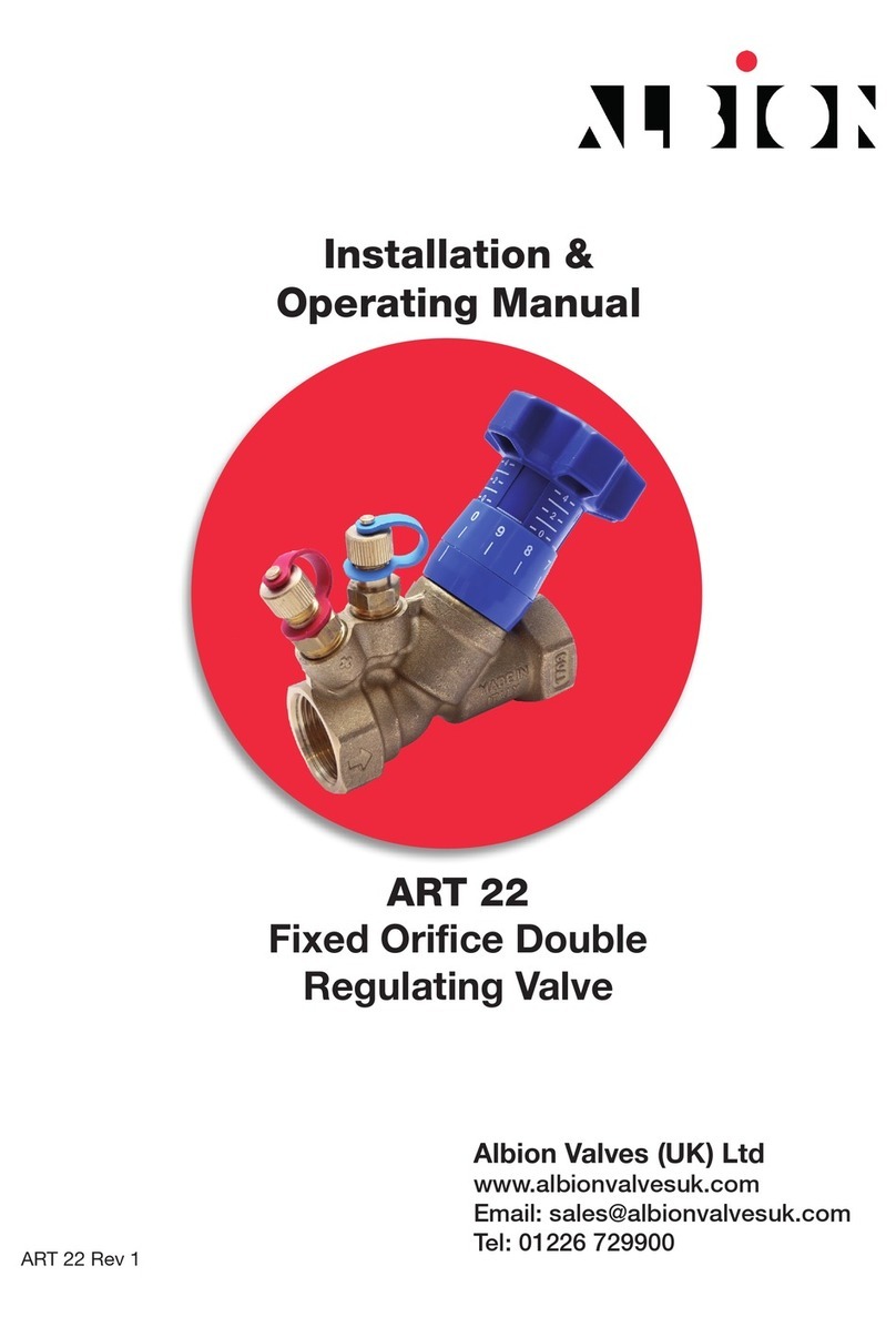
Albion ART 22 Installation instructions

Albion

Albion ART 22 Installation instructions

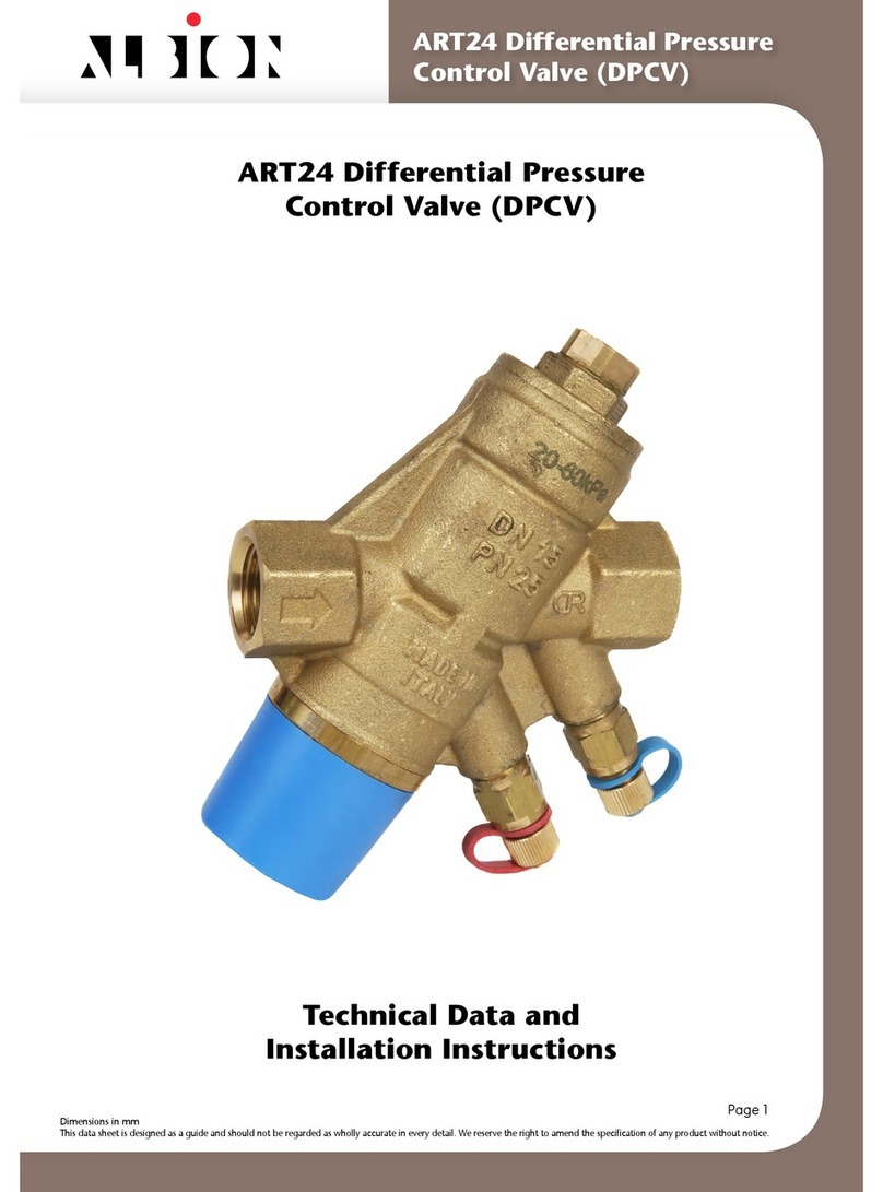
Albion ART24 Instruction manual

Albion

Albion ART24 Instruction manual

Albion ART 20C Installation instructions

Albion

Albion ART 20C Installation instructions

Albion ART 679 Installation instructions

Albion

Albion ART 679 Installation instructions

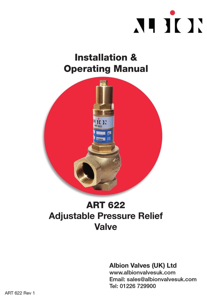
Albion ART 622 Installation instructions

Albion

Albion ART 622 Installation instructions

Albion ART 22 Instruction manual

Albion

Albion ART 22 Instruction manual

Popular Control Unit manuals by other brands

GEM 616 operating instructions

GEM

GEM 616 operating instructions

Sony PVE-500 operating instructions

Sony

Sony PVE-500 operating instructions

Allen-Bradley FLEX Ex 1797-OB4D installation instructions

Allen-Bradley

Allen-Bradley FLEX Ex 1797-OB4D installation instructions

JUMPtec superMOPSpro Technical manual

JUMPtec

JUMPtec superMOPSpro Technical manual

Monacor img Stage Line TXS-820M manual

Monacor

Monacor img Stage Line TXS-820M manual

Mitsubishi MELSEC-L Series user manual

Mitsubishi

Mitsubishi MELSEC-L Series user manual

Rockwell Automation ArmorBlock MaXum 1792D-8BT8PE installation instructions

Rockwell Automation

Rockwell Automation ArmorBlock MaXum 1792D-8BT8PE installation instructions

WAREMA GA Kompakt Operating and installation instructions

WAREMA

WAREMA GA Kompakt Operating and installation instructions

TriangleTube PGRKIT18 quick guide

TriangleTube

TriangleTube PGRKIT18 quick guide

GPS Prueftechnik Digital Colour Analyzer user manual

GPS Prueftechnik

GPS Prueftechnik Digital Colour Analyzer user manual

Aube Technologies TH132 A owner's guide

Aube Technologies

Aube Technologies TH132 A owner's guide

Siemens FDK:521H1134 operating manual

Siemens

Siemens FDK:521H1134 operating manual

Telit Wireless Solutions NL865B1 manual

Telit Wireless Solutions

Telit Wireless Solutions NL865B1 manual

Omega DRC-4720 instruction sheet

Omega

Omega DRC-4720 instruction sheet

Lenze EtherCAT E84AYCET Communications manual

Lenze

Lenze EtherCAT E84AYCET Communications manual

tiki SHB10 Installation and user manual

tiki

tiki SHB10 Installation and user manual

ASCO Valves USM8260101 Installation & maintenance instructions

ASCO Valves

ASCO Valves USM8260101 Installation & maintenance instructions

Samson 2371 Series Mounting and operating instructions

Samson

Samson 2371 Series Mounting and operating instructions

manuals.online logo
manuals.online logoBrands
  • About & Mission
  • Contact us
  • Privacy Policy
  • Terms and Conditions

Copyright 2025 Manuals.Online. All Rights Reserved.