manuals.online logo
Brands
  1. Home
  2. •
  3. Brands
  4. •
  5. P.A.
  6. •
  7. Control Unit
  8. •
  9. P.A. VB 280 User manual

P.A. VB 280 User manual

Last update: 14/07/10
1
VB 280-VB350
-UnloaderValve (discharging)
Technicalmanual:
E 237
Pressure regulating unloader valve.
At gun shut off, the water flow is bypassed at reduced pressure.
DN 10
Technical specifications
Max. flow rate: 40 l/min. Max temperature: 90°C (1)
Part Number
Rated
pressure
bar - MPa
Permissible
pressure
bar - MPa
Minimum
adjustable
pressure
bar - MPa
(2)Trapped
pressure at circuit
closure
%
(3)Pressure drop
to reset bypass
%
Inlet
Outlet
bypass
Weight
g
60.1600.00
280 - 28 310 - 31 28 – 2.8 12 44 G3/8 MF 850
60.1700.00
350 - 35 390 - 39 35 – 3.5 12 44 G3/8 MF 880
(1) The valve has been designed for a continuous use at a water temperature of 60°C. It can resist for sh ort periods at a
maximum temperature of 90°C.
(2) This is the maximum pressure increase implemented in the circuit for the intervention of the valve and to bring all the
fluid in bypass (percentage figures of the pressure set up)
(3) This is the pressure reduction necessary in comparison to the set up, in order that the valve brings back pressure in
the circuit. (percentage figures of the pressure set up)
n. 12.9237.00
Instruction manual, maintenance, installation, spare parts.
For a correct utilization, follow the directions of this manual
Re-print them on the Use and Maintenance booklet of the machine.
•
60.1600.00 VB 280 G 3/8 MF
CE
•
60.1700.00 VB 350 G 3/8 MF
- Assembly equipped with a high pressure proof compensation.
- Compact dimensions.
- Sturdy steel and brass construction.
- Adjustable locknut to control max pressure.
- Possibility to fit a venturi injector, on delivery, for chemicals.
- Nylon knob
- By-pass G1/2 F.
- Easy maintenance.
Last update: 14/07/10
2
DIMENSIONAL DRAWING
INSTRUCTIONS
SELECTION
This product is to be utilized with clean fresh water, even slightly additivated with normal detergents. For use involving different or
corrosive liquids, contact the PA Technical department. Appropriate filtration should be installed when using unclean liquids. Choose
the valve in line with the data of nominal running (system rated pressure, max flow and max temperature). In any case, the pressure of
the machine should not exceed the permissible pressure rate imprimed on the valve.
INSTALLATION
This accessory, on a system that produces hot water, must be fitted in front of the heat generator. This product is bound to be
incorporated on a finished machine. On a system that generates hot water, anticipate the fitting of accessories that limit the accidental
increase of fluid temperature.
Always install a safety valve that protects the pressurized outlet channel.
Choose a correct nozzle size, which allows a regular discharge on bypass, at least 5% of the total flow of the system in order to
achieve a constant pressure value and avoid troublesome pressure spikes at closure. If the nozzle wears out, the pressure drops.
On installation of a new nozzle, re-adjust the system to the original pressure setting
OPERATIONS
The valve regulates the the max pressure of the system through a piston, which acts on a ball that, normally positioned, closes the
bypass opening. A check valve cuts out the delivery section, the pressure of which controls the drive of the piston.
Each regulation should be made when the system is operational and the nozzle open.
ATTENTION: The nut (pos.15) must never be removed mainly because, it is a mechanical safety feature that limits the
max pressure and avoids serious damage to persons and machine.
DISCHARGE SYSTEM AND WATER ADDUCTION
The bypass line should be returned into a tank with deflectors. With elevated pressure intake, it is necessary to install a pressure
reducer in order to have an even flow supply and to protect the circuit intake.
When the system is opened and closed frequently, it is recommended to install a thermal protector valve (VT3 or VT6) in order to
eliminate excessive temperature build.
Last update: 14/07/10
3
PROBLEM HANDLING: CAUSES AND SOLUTIONS
PROBLEMS PROBABLE CAUSES SOLUTIONS
Frequent unloader recycles Damaged check valve O-Ring
Leaking connections
Restricted bypass
Replace
Check and renew
Clean or adapt
Unloader does not reach
pressure
Unloader not properly si ed
Piston O rings worn out
Material matter between seat and shutter
Worn out no le
Change spring or type of valve
Replace
Clean the seat
Replace
Pressure peaks Less than 5% of total flow in bypass
Excessive flow in bypass
Spring totally compressed
Reset
Change type of valve or adjust passages
Loosen knob and change no le
Unloader does not bypass at
low pressure
Jammed check valve
Check valve O ring worn out
Material matter on check valve
Clean or replace
Replace
Clean
Unloader causes oscillations to
the hydraulic system
Bypass system unfit
Bypass tube not properly si ed
Bypass obstructed or throttled
Stick to the installation scheme represented at the
bottom of this page, with bypass directed into the
pump
Enlarge diameter
Clean or reset
REGULATIONS : see provisional manual
The accessory hereby described bears the CE mark in compliance with provisions and regulations
indicated on the Declaration of conformity.
For a correct utilization, follow the directions described in this manual and re-print them on the Use and maintenance manual of the
machine.
Make sure that you are given the Original Declaration of Conformity for the accessory chosen. The present manual is valid for all
unloader valves type VB 280 and VB 350.
MAINTENANCE
Maintenance has to be carried out by Specialized Technicians.
STANDARD: every 400 working hours (circa 10,000 cycles), control and lubricate the seals with water
resistant grease.
SPECIAL: every 800 working hours( circa 20,000 cycles), control the wear of the seals and internal parts and
if necessary, replace with original PA parts taking care during installation and to lubricate with water resistant
grease.
ATTENTION: reassemble the valve in the correct manner paying special attention to the Nut (pos 19) which must
always be in place.
The manufacturer is not to be considered responsible for damage as a result from incorrect fitting and
maintenance-
Technical data, descriptions and illustrations are indicative and liable to modification without notice
Fig 1
Last updated 05/02/2011
60.1600.00 VB280 unload. 3/8MF Bsp byp:1/2F+knob 60.1700.00 VB350 unload. 3/8MF Bsp byp:1/2F+knob
Pos. P/N Description Q.ty K1K2K3K4 Pos. P/N Description Q.ty K1K2K3K4
1 60.1811.31 Shutter coupl., 3/8F Bsp brass 1 3
2 10.3066.01 O-ring, 1,78x15,6 mm Ni 85 2 • 10
3 60.0053.51 Spring, 0,7x9x20 mm Sst. 1 10
4 60.0052.51 Shutter pin, Sst. 1 3
5 10.3213.08 O-ring, 3x6 mm Ni 90 1 • 10
6 60.1725.35 Hous.-V280-350/4,3/8M c/snk+1/4F Bsp brs 1 3
7 60.1809.51 Seat, 11,6x19x6 mm Sst. 1 • 5
8 60.1808.51 Shutter pin, M8 Sst. 1 • 3
9 10.3068.01 O-ring, 1,78x17,17 mm Ni 85 1 • 10
10 60.1810.31 Spacer ring, 10,3x23,4x12,5 mm brass 1 5
11 60.0979.24 Stem seal, 10x14,9x2,2 mm+O-ring 1 • 5
12 10.3072.01 O-ring, 1,78x20,35 mm Ni 85 1 • 10
13 60.0973.31 Piston holder, brass (1) 1 3
13 60.1805.31 Piston holder, brass (2) 1 3
14 16.2100.00 Set screw, DIN914 M4x4 mm 1 10
15 60.1728.31 Ring nut, M27x1 brass 1 3
16 60.0978.24 Piston seal, 9x14x2,2 mm+O-ring 1 • 5
17 60.1806.51 Piston, M8 Sst. 1 3
18 14.7443.10 Ball, 11/32" Sst. 1 • 10
19 60.1813.31 Spring rest pin, brass 1 5
20 60.0975.61 Spring, 4,2x19,7x42 mm z.pl. (1) 1 10
20 60.1812.61 Spring, 4,5x15,8x47mm (2) 1 3
21 60.1727.31 Valve regulating insert, brass 1 5
22 60.1726.84 Valve regulating knob, PA black (1) 1 10
22 60.1729.84 Valve regulating knob, PA red (2) 1 10
Kit P/N Description
K1 60.1615.24 Spares kit -VB280-350/4 11x1pcs. 1
(1) 60.1600.00 (2) 60.1700.00

This manual suits for next models

1

Other P.A. Control Unit manuals

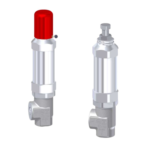
P.A. VS1100 User manual

P.A.

P.A. VS1100 User manual

P.A. VRPP 170 User manual

P.A.

P.A. VRPP 170 User manual

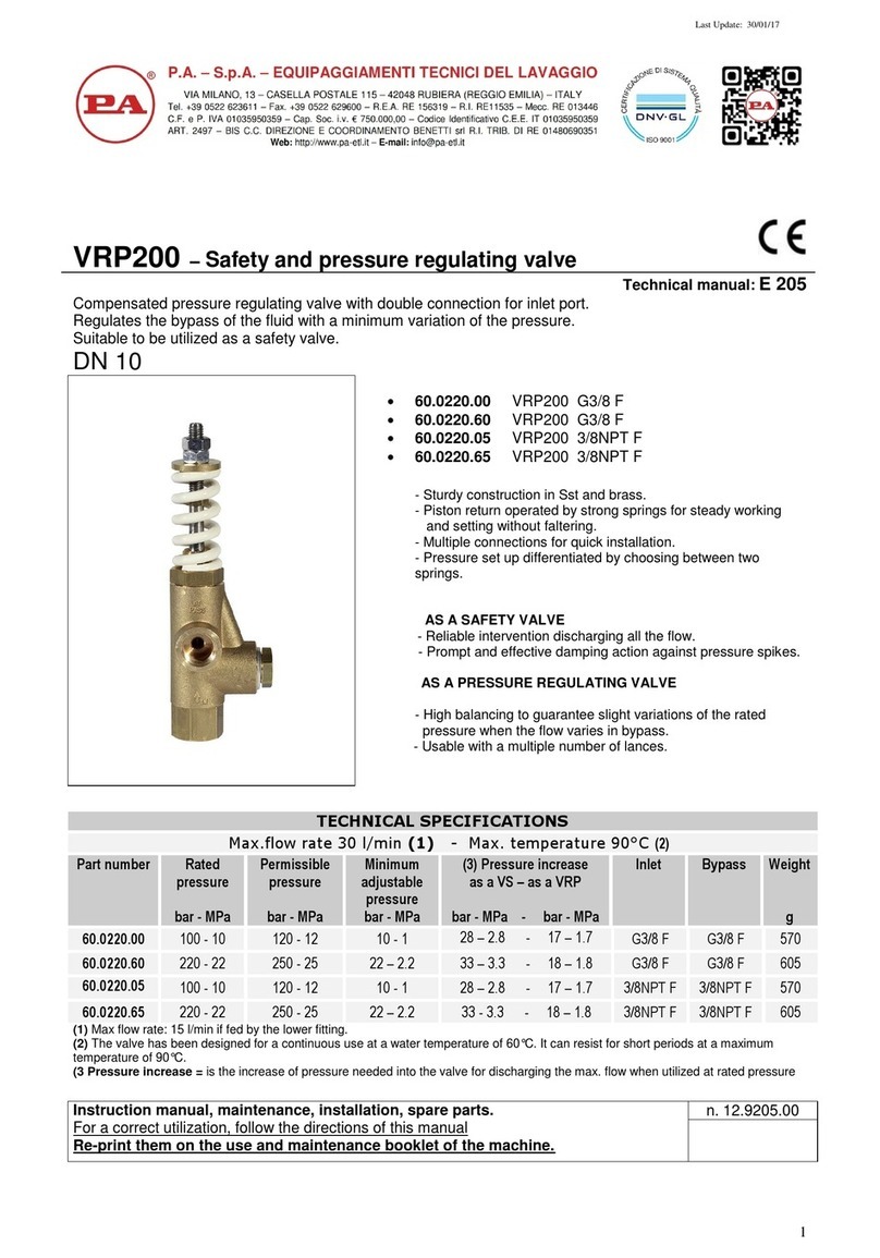
P.A. VRP200 User manual

P.A.

P.A. VRP200 User manual

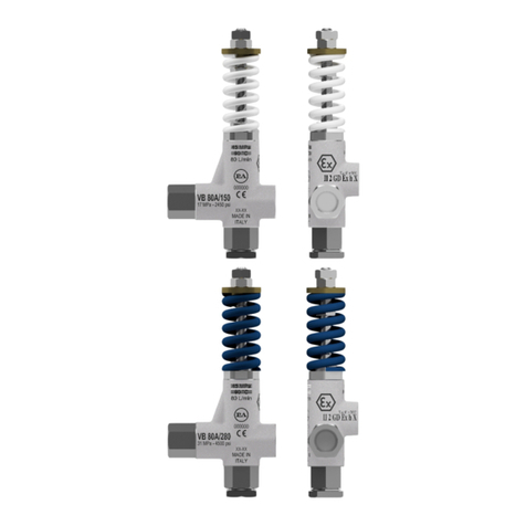
P.A. VS 80A/150 User manual

P.A.

P.A. VS 80A/150 User manual

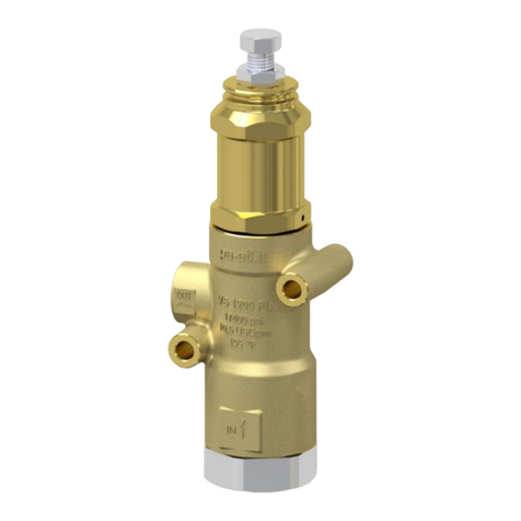
P.A. VS 1200 FL User manual

P.A.

P.A. VS 1200 FL User manual

Popular Control Unit manuals by other brands

Linear Technology DC2157A Demo Manual

Linear Technology

Linear Technology DC2157A Demo Manual

Fibocom H330S Hardware user manual

Fibocom

Fibocom H330S Hardware user manual

Airwell RCW-2 user manual

Airwell

Airwell RCW-2 user manual

Faber Blokhus installation manual

Faber

Faber Blokhus installation manual

Paxton 654-549-US instructions

Paxton

Paxton 654-549-US instructions

Emerson Rosemount Analytical NGA2000 CLD instruction manual

Emerson

Emerson Rosemount Analytical NGA2000 CLD instruction manual

Aube Technologies TH132 A owner's guide

Aube Technologies

Aube Technologies TH132 A owner's guide

Siemens FDK:521H1134 operating manual

Siemens

Siemens FDK:521H1134 operating manual

H3C NSQ1FAB04B0 manual

H3C

H3C NSQ1FAB04B0 manual

Monacor img Stage Line TXS-820M manual

Monacor

Monacor img Stage Line TXS-820M manual

Nexans XPLORER 144 - 3X48 Notice Instructions

Nexans

Nexans XPLORER 144 - 3X48 Notice Instructions

Graco Advanjet HV-2000b Setup and operation

Graco

Graco Advanjet HV-2000b Setup and operation

Honeywell ADEMCO 4204 installation instructions

Honeywell

Honeywell ADEMCO 4204 installation instructions

CAME 3199ZBX6 quick start guide

CAME

CAME 3199ZBX6 quick start guide

Advantech MIC-75G20-10B1 Startup manual

Advantech

Advantech MIC-75G20-10B1 Startup manual

Armaturen STEVI 423 Series Operating and installation instructions

Armaturen

Armaturen STEVI 423 Series Operating and installation instructions

Samson 2371 Series Mounting and operating instructions

Samson

Samson 2371 Series Mounting and operating instructions

axing Premium Line SKT 80-00 Operation instructions

axing

axing Premium Line SKT 80-00 Operation instructions

manuals.online logo
manuals.online logoBrands
  • About & Mission
  • Contact us
  • Privacy Policy
  • Terms and Conditions

Copyright 2025 Manuals.Online. All Rights Reserved.