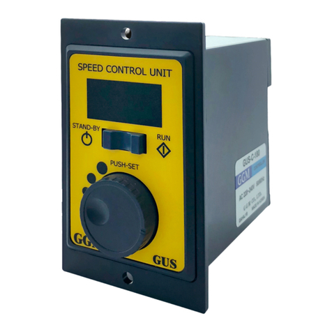
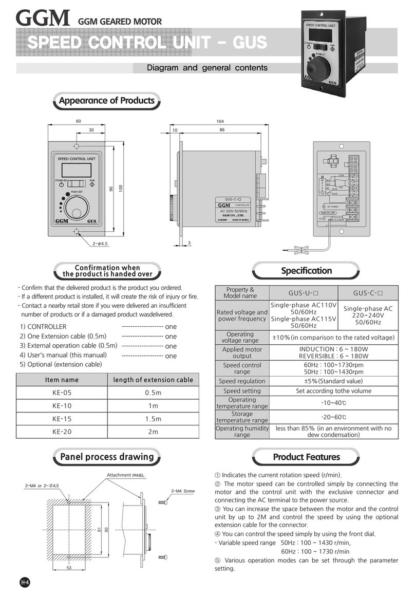
GGM GUF Series User manual

www.ggm.co.kr
GUF
SERIES
BLDC SPEED CONTROL UNIT
GLOBAL GEARED MOTOR
OPERATION MANUAL
■Headquarters / 1st Factory : 22, Gyeongin-ro 3beon-gil, Bucheon-si, Gyeonggi-do, Republic of Korea
Tel:+82-32-664-7790 Fax:+82-32-611-7791
■Attached research institute / No. 2 factory : 180, Oksan-ro, Bucheon-si, Gyeonggi-do, Republic of Korea
Tel:+82-32-684-7791 Fax:+82-32-683-5059

Thank you for purchasing a GGM product.
To ensure that you areusing this product correctly, make sure to first read this operation
manual thoroughly and familiarize yourself with allknowledge, safety information and
precautions related tothe product. After you have read this operation manual, keep it
at hand for reference whenneeded.
1. Safety precautions
In usingand operating the product, be sure to observe the following precautions. Failure to
observe the precautions may result in electric shock, injury or fire. The following precautions
are very important and should be observed at all times.
•Do not use the product near explosive materials, combustible materials,
flammable gas, corrosive materials, or anyplace where it may be splashed by
water.
Doing so may cause fire, electric shock or injury.
•Do not forcibly bend, pull or insert the motor lead wire.
Doing so may cause fire or electric shock.
•Do not move, install, connect or inspectthe product while an electric current
is being applied. Be sure to only perform repair or installationwork after
cutting off the power supply.
Failure to do so may cause an electric shock.
•Have a qualified person with relevant knowledge install, connect,
operate, control and check the product for failure.
Doing so may cause fire, electric shock or injury.
•After cutting off the power supply, allow a full minute to elapse before touchingthe
output terminal. Failure to do so may cause an electric shock.
•Be sure to cut off the power supply when the power failure protection device
or overheating protection device (thermal protector) is triggered.
Failure to do so may cause injury when the product re-starts without warning.
•Install the bldc speed controller in the housing.
Ground the protective ground terminal when it is installed.
Failure to do so may cause an electric shock or injury.
•Make sure thatthe AC power supply to the bldc speed controlleris at the rated
voltage. Failure to do so may cause a fire or product damage.
•Do not disassemble or modify the motor orthe speed controller. Failure to do so
may cause an electric shock or injury.
Ignoring thesewarnings may cause death
or serious injury.
2
Warning

2. Confirmation when the product is handed over
- Confirm that the delivered product is the product you ordered.
- If a different product is installed, it will create the risk of injury or fire.
- Contact a nearby retail store if you were delivered an insufficient number of products or
if a damaged product wasdelivered.
1) CONTROLLER
2) user's manual (this manual)
3) optional (extension cable)
------------------- One
If the controller is far away
from the motor, refer to
the optional specification
specified in the table above.
3. Specifications
3
MODEL length of
extension
cable
KFEW-1 K10FEW-1 1m
KFEW-2 K10FEW-2 2m
KFEW-3 K10FEW-3 3m
KFEW-5 K10FEW-5 5m
KFEW-7 K10FEW-7 7m
KFEW-10 K10FEW-10 10m
200, 400W30, 60, 150W
Part Number
Rated Output Power
(Continuous)
GUF-C-30
30W
GUF-C-60
60W
GUF-C-150
150W
GUF-C-200
200W
GUF-C-400
400W
Rated voltage
Rated frequency
Rated input
current
Maximum
input current
Single-phase : 200~240V / three-phase : 200~240V ( Permissible range ±10 % )
50 / 60 Hz ( Permissible range ±5 % )
Rated Output Current
Rated Torque
Maximum Instantaneous Torque
Rated Speed
Speed Control Range
Speed Regulation
Power
input
Temperature
Humidity
Environment
Input signal
Output signal
3000 r/min
100~4000 r/min
0.5% or less/ Conditions : 0~RatedTorque, Rated Speed, Rated Voltage, Normal Temperature
Use : 0 ~ 40℃(Non-freezing), Storage : -20 ~ 70℃(Non-freezing)
Use : 85%below(Non-condensing), Storage : 85%below(Non-condensing)
No corrosive gas and dust, No splashing water and oil
5 user inputs ( Photocoupler )
3 user outputs ( Photocoupler )
Single-Phase
0.8A
Three-Phase
0.5A
Single-Phase
1.9A
Three-Phase
1.1A
0.17 A
0.1 N.m
0.15 N.m
Single-Phase
1.0A
Three-Phase
0.7A
Single-Phase
2.8A
Three-Phase
1.7A
0.43 A
0.2 N.m
0.3 N.m
Single-Phase
2.0A
Three-Phase
1.2A
Single-Phase
4.5A
Three-Phase
2.6A
0.95 A
0.49 N.m
0.60 N.m
Single-Phase
2.5A
Three-Phase
1.8A
Single-Phase
5.5A
Three-Phase
3.2A
1.60 A
0.65 N.m
1.15 N.m
Single-Phase
4.0A
Three-Phase
3.0A
Single-Phase
7.8A
Three-Phase
5.0A
2.30 A
1.30 N.m
1.80 N.m
Operating
Environment
Input
output

4. CONTROLLER CODING SYSTEM
5. Dimensions of the product
G U F C 30
30 : 30W
60 : 60W
150 : 150W
200 : 200W
400 : 400W
C : POWER
Single Phase 200~240V
Three phase 200~240V
F-SeriesUnit
Type
GGM
Co.,LTD.
4
■
■
58
90
4
111
116
STAND-BY RUN
FWD
REV
GGM
GGM
CN3 SENSOR CN2 MOTOR
CN4 I/O
CN1 200-240V
80
52
2-∅4.5 HOLE
98
2- 4.5 THRU∅
2-M3 DP8
64.5
104.5
124
CN1 200-240V
CN4 I/O
CN3 SENSOR CN2 MOTOR
125
7.8
STAND-BY RUN
FWD
REV
GGM
GGM
90
115
60
17
17
4.5
30,60,150W drives
200,400W drives

6. Product characteristics
1. Stable speed control ( Speed ripple: 0.5% )
The product adjusts the current applied to the
motor through vector control by constantly
comparing the set speed with the speed
feedback signal from the motor, enabling
stable rotation speed from low speed to
high speed even if the load changes.
2. Wide speed control range
Speed : 100 ~ 4000 r/min
3. Simple connection
•The motor connector can
be wired simply.
•Connect the lead wire to
the power connector
using the screw driver.
•Connect the lead wire to
the I/O connector by pressing the button.
4. Simple use ( front panel )
5
•Run and stand-by control
Operate the product simply
by using the operation
switch.
•Rotational direction control
Change the rotational
direction of the motor using
the rotational direction switch.
•Speed control
The speed can be easily
controlled and various
functions executed using the
speed control buttons.
5. Operation by external I/O ( PLC, etc. )
Start/Stop, change of rotational direction,
multi-level speed operation by external I/O,
etc.
6. Display indication
(load ratio, actual speed, etc.)
Display of load ratio
(100%)
Display of actual speed
(1500rpm)
7. Multi-level speed operation ( 8 speeds )
8-speed operation is available by setting data
to operation data No.0 ~ No.7.
8. Setting/operation lock
( Prevents speed or data changes )
- Set the Lock function: Press and hold down
the (S) button for 5 seconds or longer.
- Cancel the Lock function: Press and hold
down the (S) button for 5 seconds or longer.
9. Protection function
The product is equipped with a function that
enables it to detect abnormal status such as
overload and overvoltage.
If an abnormality is detected, operation will
stop and an alarm will occur.
7. Applicable Motor
Item name
Rated output
Rated torque
Rated output current
Rated rotation speed
K6F□30NC
30W
0.1 N.m
0.17 A
K8F□60NC
60W
0.2 N.m
0.43 A
K9F□150NC
150W
0.49 N.m
0.95 A
K10F□200NC
200W
0.65 N.m
1.60 A
K10F□400NC
400W
1.3 N.m
2.30 A
3,000 r/min
* □ : SHAFT SHAPE ( S : STRAIGHT, H : PINION )

6
8. Name and function of each part
9. Setting and operation
9-1 Connect
55
44
33
22
11
RG1RG1
RG2RG2
L3L3
L2L2
L1L1
Single Phase
200-240V
55
44
33
22
11
RG1RG1
RG2RG2
L3L3
L2L2
L1L1
Three phase
200-240V
•Connect AC power supply to CN1 according to the input
power supply.
Applied lead wire - AWG 18~14 ( 0.75~2.0mm²)
•when reduction time is short or big inertias operated, use
restoration resistance.(100W/400ΩJ)
55
44
33
22
11
RG1RG1
RG2RG2
L3L3
L2L2
L1L1
Regenerative
resistor
▶ Connecting ▶ Connecting the power supply
9-2 Inputting the power
Turn on the power after connect with above.
Indicator light
Display item : Setting speed
•How to disable the alarm when the power is turned on in the RUN state
[Change to oP.AL oFF in parameter mode (p. 14)]
If the operation switch “RUN” when power
turning on, the alrarm code “ AL.oP ”
(Pervention of operation at power-on
alarm) is displayed and the do not
operated motor.
Set the operation switch from “RUN” to
“STAND-BY” for release an alarm before
use motor.
Attention
Display unit
[Displays the rotation speed
and parameters]
Operation switch
[When you toggle the operation
switch to RUN,
the motor rotates when you toggle
the operation switch to STAND-BY,
the motor stops.]
Rotational direction switch
[Changes the rotational direction of
the motor]
Setting button
[Changes the rotation speed and
parameters]
Protection ground terminal
[Connects the protection ground
wire.]
Motor power connector CN2
[Connects the motor power
connector.]
Motor sensor connector CN3
[Connects the motor sensor
connector.]
Power connector CN1
[Connects the AC power supply
(single-phase/three-phase).]
I/O connector CN4
[Connects I/O signals.]
Connecting the sensor
connector(6Pin)
CN3 Connecting the motor
connector(4Pin)
CN2
Connecting
the power CN1
Protection ground terminal
Be sure to ground.

9-3 Operating
After turning on the power, operate the product as follows.
④ To stop running
the motor
① To start runing
the motor
② To adjust the motor
rotation speed
③ To determine the
setting of the motor
rotation speed
① Running the motor
Set the operation switch to the “RUN”, the motor to start rotating .
② Adjust the speed
When pressing the “+” button, the rotation speed accelerates by 1r/min increment and when
pressing the “-“ button, the rotation speed decelerates by 1r/min decresment.
When press and hold the“+”,”-“ button, RPM will acceleration and deceleration
by 1rpm->10rpm->100rpm.
③ Rotation Speed Confirmation and Lock
- When pressing the “S” button, the rotation speed is determined.
When the display is blinking, the rotation speed has not set.
- Can lock the operation by pressing the “S” button for more than 5 seconds in the “STAND-BY”
mode for can not change the definite rotation speed.
④ Stopping the motor
Setting the operation switch to the “STAND-BY” side causes the motor to decelerate to a stop.
Setting the operation switch again to the “RUN” side causes the motor to start rotating at the
set rotation speed.
⑤ Changing the rotation direction
Change the rotation direction of the motor (gearhead) using the rotation
direction switch. The rotation direction can be changed while operating.
With the combination type, the rotation direction of the gearhead output
shaft varies depending on the rear ratio of the gearhead.
7

9-4 Operating by I/O signals
The motor can be operated and stopped from the external signals.
① Setting the “External operation signal input” parameter
Set the parameter (PAr-> io.En-> on / oFF) to "on" (page 14)
"on"-External I / O enabled, "oFF"-External I / O disabled / The factory setting is "oFF".
② Run command [Run when FWD or REV input is ON]
Forward rotation when FWD (No. 2) + LCOM (No. 7)
connected / Reverse rotation when REV (No. 3) + LCOM (No. 7) connected
(Operation should be made with front control Run position, no operation at stand-by)
③ Pin allotment of CN4
8
Applicable lead wire AWG 26~20 ( 0.14~0.5mm² )
※ Function in [ ] is assigned at shipment
※ Can be assigned required functions to 5 input signals(X0~X4) and 3 output signals(Y0~Y2)
•Input signals : Can be used 5 functions out of FWd(CW rotation), rEv(CCW rotation), P0 (operation
data 1), P1(operation data 2), P2(operation data 2), A.rst(Alarm reset), E.Err(External alarm)
•Output signals : Can be used 3 functions out of SPd(Speed output), AL.on( Alarm output),
AL.ov(Overvoltage alarm output), OvLd(Overload alarm output), MovE(Motor operation output)
Pin
No.
1
2
3
4
5
6
7
8
9
10
11
12
13
X0
X1
X2
X3
X4
LCOM
Y0+
Y0-
Y1+
Y1-
Y2+
Y2-
Terminal
Name
HCOM
Input
Output
Common
Signal
Name
ㅡ
Description
Input signal common : Sink Logic : +24V,
Source Logic : 0V (GND)
Input
Input
Input
Input
Input
Common
Output
Output
Output
Output
Output
Output
[FWD]
[REV]
[P0]
[P1]
[A.rst]
-
[SPD]
[AL.on]
[MovE]
The motor rotates is FWD direction during signal “ON
The motor rotates is REV direction during signal “ON”
Select the operating data
Reset the alarm
Input signal common
For every rotation of the motor, 30 pulses are output
It turns off when an alarm is generated (Normally closed)
It turns on when the motor is operated (Normally opened)
Motor Drive I/O Signal
AC power input

9
④ Timing chart example
※ Operation input
•The motor rotates when either FWD input or REV input is set to “ON”.
•The motor instantaneous stop when FWD input and REV input is set to “ON” at the
same time.
⑤ Connection example for I/O signals and programmable controller
This is connection example for operating a motor using a transistor output type
programmable controller.
Attention) For the Y0, Y1 and Y2, be sure to keep the current value at 100mA or less.
If the current exceeds this value, connect the limiting resistor R.
※ 1) Limited resistance
In the case of 24V DC : 680Ω~2.7Ω (2W)
In the case of 5V DC : 150Ω~560Ω (0.5W)
2) Twisted Pair
Shield Cable
Motor Movement
Operating Switch
50ms
or more
10ms or more
Drive
Programmable controller Drive
Programmable controller
Deceleration
Stop
Deceleration
Stop
Deceleration
Stop
Instantaneous
Stop
FWD input
REV input

10
⑥ Driving at two or more speeds
You can operate at two or more speeds by switching to external input.
Up to 8 speeds are possible.
•Operating method
Operate the motor by selecting any of the operation data No.0 to No.7 based in a combination
of ON/OFF status of the P0, P1 and P2 inputs. The motor is operated using the rotation speed,
acceleration time, deceleration time and torque limit in the selected operation data number.
•Operation procedure (When the “external operation signal input” parameter is set to “ON”)
1. Set the operation switch to “RUN” side
2. Select the operation data number suing the P0, P1 and P2 inputs
3. When the FWD or REV input is turned ON, the motor will rotate.
4. Switch the operation data number using the P0, P1, and P2 inputs
5. When the FWD or REV input switch has been turned ON or is turned OFF, the motor will stop.
* Setting speed value is example, can be changed to needed speed.
When changing from the present speed to the new speed, the acceleration time and
deceleration time set in the next operation data number are used.
Operation data number
0
1
2
3
4
5
6
7
P0
OFF
ON
OFF
ON
OFF
ON
OFF
ON
P1
OFF
OFF
ON
ON
OFF
OFF
ON
ON
P2
OFF
OFF
OFF
OFF
ON
ON
ON
ON
Rotation speed
[rpm]
1000
500
2000
1500
3000
2500
4000
3500
Motor speed
Operating Switch
P0 input
P1 input
P2 input

11
10. Setting and 7-segments display
10-1 Monitor mode

12
10-2 Input/Output setting mode

10-3 Parameter setting mode(1page)
13

10-3 Parameter setting mode(2page)
14

10-3 Parameter setting mode(3page)
15

10-3 Parameter setting mode(4page)
16

10-4 saving mode
17
Description
Sets the acceleration time.
Sets the deceleration time
Sets the torque limit
Sets the time to output the alarm
after detecting the overload
condition when a load up to the
limited duty region exceeding the
continuous duty region was applied.
Sets the upper limit of the rotation
speed.
Sets the lower limit of the rotation
speed.
Sets the speed reduction ratio
relative to the rotation speed of the
motor output shaft.
Displays the speed calculated based
on the speed reduction ratio on the
monitor mode.
If the speed reduction ratio for
the conveyor is calculated and input,
the conveyor speed can also be
displayed.
When increasing the motor rotation
speed using the external input, the
converted speed can be displayed.
After the power is turning on, the
item displayed on the monitor
mode can be changed.
Item
Acceleration time
Deceleration time
Torque limit
Overload alarm
detection time except
when holding a shaft
Speed upper limit
Speed lower limit
Speed reduction ratio
Speed increasing ratio
Panel initial display
Display
Pr.tA
Pr.td
Tq.LM
oL.tM
SP.Hi
SP.Lo
Gr-r
SP-r
P.dSP
Setting range
0.0 ~ 15 s
0.0 ~ 15 s
10~300
0.1 ~ 60 s
50 ~ 4000 rpm
50 ~ 4000 rpm
1.00 ~ 9999
1.00 ~ 2.00
SPd – Rotation speed(r/min)
Load – Load factor (%)
oP.no – Operation data
number
Factory
setting
0.5 S
0.5 S
300
40 S
4000 rpm
50 rpm
1.00
1.00
SPd
11. Parameter list

18
Setting range
on – Enable
oFF – Disable
oFF – Disable
on – Enable
FWd – FWD
rEv – REV
P0 – Operation data 0
P1 - Operation data 1
P2 - Operation data 2
A.rSt – Alarm reset
E.Err – External error
---- - Not used
SPd – Rotation speed
AL.on – Alarm on
AL.ov – Overvoltage
OvLd – Overload
Tq.LM – Torque limit
MovE – Motor operation
vA – Rotation speed
WnG – Warning
---- - Not used
1 ~ 400 rpm
0 – User setting
Factory
setting
on
oFF
FWd
rEv
P0
P1
A.rSt
SPd
AL.on
MovE
200 rpm
Initial value
0
•When setting the speed increasing ratio to 1.00, the speed reduction ratio
will be effective.
•When setting a longer time in the “overload alarm detection time except
when holding a shaft” parameter, an overload status may continue.
Repeating this condition may result in shorter service life of the motor and
gearhead.
•If a load exceeding the limited duty region was applied or output shaft was
holded, the “overload alarm detection time except when holding a shaft” is
maximum 5 seconds.
Attention
Item
Prevention of operation
at power–on alarm
External I/O function
External input function
X0 input function selection
X1 input function selection
X2 input function selection
X3 input function selection
X4 input function selection
External output function
Y0 output function
selection
Y1 output function
selection
Y2output function
selection
Rotation speed
attainment band
Initialize the parameter
mode
Developer setting
Display
oP.AL
io.En
in
in.0
in.1
in.2
in.3
in.4
oUt
oUt.0
oUt.1
oUt.2
At.bd
init
S.USr
Description
Sets whether to enable or disable the
“prevention of the operation at
power on alarm”
The operation method can be selected
between the front panel and external
input signals.
When operating or stopping the motor
using the external input signals, the
functions of the operation switch,
rotation direction switch, and setting
button can be set to disable.
External input setting.
Assigns the input signals to the
external input terminals.
External output setting.
Assigns the output signals to the
external output terminals.
Sets the band within which the
rotation speed of the motor is
deemedto have reached the set
value.
Restores the value set in the
parameter mode to the factory
setting.
Developer setting

19
12. Description of I/O signals
Description
The motor rotates when either FWD input or REV input is set to “ON”.
The motor instantaneous stop when FWD input and REV input is set
to “ON” at the same time.
These signals are used to select the operation data number.
8 speeds can be specified by using three opertation datas.
This signal is used to reset the alarm when be operated protection function.
When turning this signal OFF, an alarm generates and the motor stops
instantaneously.
This input is not assigned to any signal.
Display
[FWd]
[rEv]
[P0]
[P1]
[P2]
[A.rSt]
[E.Err]
[----]
Function
FWD
REV
Operation data 0
Operation data 1
Operation data2
Alarm reset
External error
Not used
Assignable alternative input functions
Description
For every rotation of the motor, 30 pulses are output
SPEED [RPM] = (SPEED-OUT [Hz] * 60 [Sec]) / 30 [pulses]
It is output when an alarm is generated (Normally closed)
It is output when an alarm is finished (Nomally open)
It is output when overload alarm is generated or exceeded
(Normally closed)
It is output when the torque limit is reached.
It is output when motor is operated.
It is output when the motor rotation speed becomes equal the value set
by the rotation speed attainment band parameter.
It is output when a warning generates. (The motor will continue to
operate.) when the warning is released, it will automatically turn OFF
This input is not assigned to any signal.
Display
[SPd]
[AL.on]
[AL.ov]
[OvLd]
[tq.LM]
[MovE]
[vA]
[WnG]
[----]
Function
Rotation speed
Alarm output
Over voltage
alarm
Overload alarm
Torque limit
Motor operation
Rotation speed
attainment
output
Warning output
Not used

13. Alarm list
•Check the power supply voltage
•Check the wiring of the power
supply cable
•The power supply voltage
be-camelower than approximately
60% of the rated voltage
•The power supply voltage
exceeded approximately 120% of
the rated voltage.
•Vertical drive(gravitational
operation) was performed or a
load exceeding the permissible
load inertia was driven.
•The temperature inside drive
exceeded the alarm detection
temperature.
•Excessive current has flown
through the drive due to ground
fault. Etc.
•Actual speed and set speed are
different.
•The motor sensor signal line
experienced an open circuit during
operation or the motor signal
connector came off.
•The rotation speed of the motor
output shaft exceeded
approximately 4800rpm
•A load exceeding the continuous
duty region was applied to the motor
for the time exceeded the value set
in the “The overload alarm detection
time” parameter.
•When the power is turned on
with the operation switch set to
the "RUN" side.
•When the power is turned on
while the FWD input or REV input is
set to “ON”.
•The motor instantaneous stop
when EXT-ERROR(Stop) input.
•Check the power supply voltage
•If this alarm occurs during
operation, reduce the load or
make the acceleration/deceleration
time longer.
•Review the ambient temperature.
•Check the wiring between the
drive and motor for damage.
•Check the power supply voltage.
•Check the load.
•Check the wiring between the
drive and motor.
•Reduce the load
•Review the operation pattern
such as acceleration/deceleration
time.
•Set the operation switch to the
“STAND-BY”
•Turn the FWD input or REV input
from ON to OFF.
•.Check the EXT-ERROR input..
Change status from activated to
deactivated
표 시 Alarm type Cause Remedial action
[AL.UV.] Under
voltage
[AL.oV.] Over voltage
Overheat
Overcurrent
[AL.oT.]
[AL.oC]
[AL.SF]
[AL.SS]
[AL.oS]
[AL.oL]
[AL.oP]
[AL.Et]
External Error
(From external
input signal)
Operation at
power-on
Overload
Overspeed
Sensor error
(Hall sensor)
Speed
feedback
Alarm
code
※ Contact your vendor or our second factory if you haveany questions about
product or requirepost-sales service.
Leader of geared motor GGM CO.,LTD. http://www.ggm.co.kr
Headquarters / 1st Factory
22, Gyeongin-ro 3beon-gil, Bucheon-si,
Gyeonggi-do, Republic of Korea
TEL : 032-664-7790 FAX : 032-611-7791
Attached research institute / No. 2 factory
180, Oksan-ro, Bucheon-si, Gyeonggi-do,
Republic of Korea
TEL : 032-684-7791 FAX : 032-683-5059
This manual suits for next models
17
Table of contents
Other GGM Control Unit manuals
Popular Control Unit manuals by other brands

Intermatic
Intermatic SS8 Series Installation and operating instructions

Watts
Watts 775 Series Installation, service & maintenance manual

Cooper
Cooper Scantronic 95 installation instructions

Elan
Elan IRD10 manual

Armstrong
Armstrong GP-2000 Installation, operation and maintenance

oventrop
oventrop Combi 4 manual