Albion TCT50 User manual

OPERATING MANUAL AND USER GUIDE
TCT50 & TCT100
www.albionamps.com
TCT 50.indd 1 2011-5-5 18:32:00

TCT 50.indd 2 2011-5-5 18:32:00

Contents
Important Safety Instructions ...................................................................................... 1
Important Warnings ....................................................................................................... 2
Designer's Introduction................................................................................................. 3
Outline Specication ..................................................................................................... 3
TCT50 & TCT100 Features and Controls...................................................................... 5
Rear Panel....................................................................................................................... 7
Specication................................................................................................................... 8
TCT 50.indd 3 2011-5-5 18:32:01

OPERATING MANUAL AND USER GUIDE
Important Safety Instructions
1. Read these instructions – All the safety and operating
instructions should be read before this product is
operated.
2. Keep these instructions – The safety and operating
instructions should be retained for future reference.
3. Heed all warnings – All warnings on the appliance
and in the operating instructions should be adhered
to.
4. Follow all instructions – All operating and use
instructions should be followed.
5. Do not use this apparatus near water – The appliance
should not be used near water or moisture – for
example, in a wet basement or near a swimming pool
etc.
6. Clean only with dry cloth.
7. Do not block any ventilation openings. Install in
accordance with the instructions.
8. Do not inst all near any heat sources such as
radiators, heat registers, stoves, or other apparatus
(including ampliers) that produce heat.
9. Do not defeat the safety purpose of the polarized or
grounding plug. A polarized plug has two blades with
one wider than the other. A grounding plug has two
blades and a third grounding prong. The wide blade
or the third prong is provided for your safety. If the
provided plug does not t into your outlet, consult an
electrician for replacement of the obsolete outlet.
10. Protect the power cord from being walked on or
pinched par ticularly at the plugs, convenience
receptacles, and at the point where they exit from the
apparatus.
11. Only use attachments/accessories specified by the
manufacturer.
12. Use only with the cart, stand, tripod, bracket or
table specied by the manufacturer, or sold with the
apparatus. When a cart or rack is used, use caution
when moving the cart/ apparatus combination to
avoid injury from tip-over.
13. Unplug the apparatus during lightning storms or when
unused for long periods of time.
14. Refer all servicing to qualied personnel. Servicing is
required when the apparatus has been damaged in
any way including: power supply cord or plug damage,
liquid spillages, objects falling into the unit, exposure
to rain/moisture or impact damage.
15. Please keep the unit in a well ventilated environment.
16. CAUTION: These servicing instructions are for use
by qualified service personnel only. To reduce the
risk of electric shock, do not perform any servicing
other than that contained in the operating instructions
unless you are qualied to do so.
17. WARNING: To reduce the risk of re or electric shock
do not expose this apparatus to rain, moisture and
dripping or splashing of liquids. Containers filled
with liquids such as vases or drinks should never be
placed on top of or near the unit.
18. WARNING: The mains plug/appliance coupler is used
as disconnect device, the disconnect device shall
remain readily operable.
19. The lightning ash with arrowhead symbol is to alert
the user to the presence of non-insulated "dangerous
voltage" within the product's enclosure that may be
of sufcient magnitude to constitute a risk of electric
shock.
- Warning: To reduce the risk of electric shock, do
not remove cover (or back) as there are no user-
serviceable parts inside. Refer servicing to qualied
personnel.
1
TCT 50.indd 4 2011-5-5 18:32:01

series
- The exclamation point within an equilateral triangle
is intended to alert the user to the presence of
important operating and maintenance instructions in
the literature accompanying the appliance.
20. Protective earthing terminal. The apparatus
should be connected to a mains socket outlet with a
protective earthing connection.
21. Correct Disposal of this product. This marking
indicates that this product should not be disposed
with other household wastes throughout the EU. To
prevent possible harm to the environment or human
health from uncontrolled waste disposal, recycle
it responsibly to promote the sustainable reuse of
material resources. To return your used device,
please use the return and collection systems or
contact the retailer where the product was purchased.
They can take this product for environmentally safe
recycling.
22. WARNING: The terminals marked with the symbol of
“ ” may be of sufficient magnitude to constitute a
risk of electric shock. The external wiring connected
to the terminals requires installation by an instructed
person or the use of ready-made leads or cords
according to manufacturer’s instruction.
23. “Class 2 Wiring“ for all other TERMINALS provided
the audio output power exceeds 10W per channel
under normal operating conditions or the apparatus is
intended to be installed or interconnected in the eld
by a SKILLED PERSON.
Important Warnings
ALWAYS read the manual of your new amplifier –
even if you are experienced with guitar ampliers and
their technology! There could be something important
that you need to know.
ALWAYS check that your new amplier is suited to the
mains power supply in your country.
NEVER disconnect the earth (ground) connection
from your amplifier. It is there to prevent you from
receiving a fatal electric shock!
NEVER use your amplifier equipment in a high
moisture environment (such as rain) or allow it to get
wet.
ALWAYS use correct and well maintained cables for
all inter-connections whether for power, speaker or
signal connections. If in any doubt, get them checked
or renew immediately.
NEVER use your amplier products with any cooling
vents covered, even partially. Your amp loves being
fed nice cool air!
PARTICULARLY with valve (tube) amps allow your
amp to warm up before playing, 5 minutes is a
good length of time. Also allow your amp to have a
good cool down after playing and before moving it,
especially into the back of a car on a cold winter’s
night! Your valves will last longer if you give them a
little respect and TLC. Valves are pretty tough when
you think of what they are made from – but can be
very fragile if treated with physical abuse.
ALWAYS use a cable rated for loudspeaker connection
use for connecting your amplier to your loudspeaker
system. DO NOT use a screened guitar cable for
speaker use.
NEVER use your amplifier without it connected to a
suitable matched loudspeaker system.
WARNING! Sometimes parts of the outside of your
amplier may get hot to the touch. This is quite normal
and will be within safe operational limits. These
limits are set by various countries safety approvals
committees, and we at Albion Musical Instruments
design, build, test, and have approved our products to
these international standards. I.e. CE, UL, CSA, CB,
ETL etc.
EMC INTERFERENCE. Even though all Albion
Musical Instruments products are designed and
tested to international electro-magnetic interference
standards, please note that cellular phones in close
proximity may cause some interference with your
amplier.
ALWAYS have your amplier serviced by a technician
qualified in servicing musical instrument amplifier
products. If in doubt please contact your dealer.
2
TCT 50.indd 5 2011-5-5 18:32:01

OPERATING MANUAL AND USER GUIDE
Designer's Introduction
When I sat down with a blank piece of paper (well actually
as this is the 21st century, a blank computer screen) to
design the TCT range of ampliers, I had a long hard look
at all the guitar amps that I had designed previously. Even
though many of those designs were destined to be what
can only be called Classics, I wanted to approach these
new amps in a different perspective. Instead of designing
under the corporate image of whatever company I was
working for at the time, the TCT amps were for the first
time “my” amps. This put the image in my mind as “what
do I want from an amp, and how do I want it to look”. As
a guitar player of many years I have used many different
amps, many times different ones hooked up in a multi-
amp set up for the different sounds that I needed at the
time. This realisation formulated the basic concept and
functionality of the direction I needed to go in, something
that was simple to use but was as variable as possible.
Oh, and sounded great at everything it did as well!
The “what do I want it to look like” actually developed
pretty quickly – I wanted something that looked classy
and stood out from the crowd, something that at the same
time was familiar yet unique. For want of a better word
“boutique”.
I think that the TCT series of Albion amps fulls my dream
and desire with room to spare. Finally “my” amp!
I personally love playing these amps and can sit there
playing them for hours on end without tiring of them –
sometimes to the annoyance of my small team I have to
add – I do tend to play very loud at times, and they do
have to work!
I hope that you get as much playing pleasure out of your
TCT amp as I do.
Thank you
Outline Specication
The TCT50 (50 watt head, 2 x EL34), TCT100 (100watt
head, 4 x EL34) and utilise the same amplier chassis but
with a different number of output EL34 valves and required
transformers, biasing etc. The TCT50C (2 x 12” combo,
2 x EL34) has the same chassis and circuit as the TCT50
head but in an “upside down” conguration. The amplier
has 2 separate switchable channels, both featuring the
same controls per channel. Channel A features the EQ
circuit before the gain stages, whilst Channel B features
the EQ after the gain stages.
Both channels feature the capability of running (depending
on control settings) from “clean” through “crunch” to “high
gain lead”. But due to the different “voicing” provided
by the EQ position (and other voicing elements), both
channels have an entirely different spectral response and
player’s “feel”.
The TCT50 and TCT100 also has the ability to mix both
channels together (footswitchable) making them capable
of 3 channel operation.
The player himself can choose which he prefers for his
particular style and suitability.
There is no xed Clean or Lead channel that can be the
limiting factor on other makes of multi channel guitar
amplifiers. This flexibility sets the Albion TCT guitar
ampliers apart from other brands.
The TCT 50/100 amplier circuit utilizes a combination of
technologies to provide optimum performance required for
high class consistent playing night after night.
The preamplifier section uses 4 double triode low noise
7025/12A X7/ECC83 valves (tubes) with high speed
relay switching for circuit reconfiguration when channel
switching.
The input gain itself is a very special proprietary circuit
combining a preamp valve mixed with a unique high
voltage FET (eld effect transistor). This circuit has many
benefits that are not readily available with tube only
designs, in that the input stage noise (particularly heater
hum) is greatly reduced, rst stage microphony is vastly
reduced, input stage gain and drive capability is increased
allowing it to drive the rest of the preamp better, and
lastly it imparts a tonality approaching that of a pentode
tube, which is good in its own right! All this means is that
the input stage will perform better and more reliably by
reducing the things you DON’T want from a tube!
A word about the EQ system used on the Albion TCT
range of amps. Although the tone controls are based on
the time honoured interactive passive system historically
used on most guitar amps, our design is somewhat wider
ranging than most others. For instance the MIDDLE
control has a much wider range than normal and will give
3
TCT 50.indd 6 2011-5-5 18:32:02

series
a substantial amount of mid boost as well as mid cut.
The result of this opens up a whole new range of sound
possibilities that we think you will enjoy. For instance using
the mid boost capability gives rise to some very sweet
singing sustain – great for blues and fusion.
The preamplier’s twin channel output is then mixed into
the FX loop and digital Reverb system. This section is
unashamedly solid state as this section is designed to be
as transparent as possible in passing all the valve tone
of the preamp to the input of the all tube power amplier
section, whilst handling the duties of efficient real world
FX loop connection, digital reverb connection, and noise
free seamless channel switching.
In MIX mode a Balance control allows the MIX level to
be adjusted higher or lower than the A/B volume level
enabling the MIX to be used as a Lead boost for instance.
The TCT50/100 power amplifier uses a 12AX7/ECC83
phase splitter and either 2 or 4 off EL34 output valves
respectively for classic high power guitar amp punch.
The power amp section can be switched between two
feedback networks. Loose gives a raw, open, vintage style
to the sound with lots of player feel and tactile response.
Tight gives a much tighter modern response to the sound
and feel.
The output section can also be run at 33% (approx 16.5
watts for TCT50, and 33watts for TCT100) of its total
output power for those situations when at out really is “too
loud”!
The TCT50C combo comes complete with two of our own
designed and built Albion loudspeakers.
4
TCT 50.indd 7 2011-5-5 18:32:02

TCT50 & 100 Features and Controls
INPUT – Mono ¼” Jack socket for instrument input. Use
a properly screened “guitar” cable for interconnection.
There are many different makes of guitar cable available,
ranging from fairly inexpensive to very expensive.
Each have different characteristics, and depending on
your particular guitar will give different results, all very
confusing for the inexperienced! For instance, a “cheap”
cable with high capacitance (which would normally be
termed as a “not very good cable”) can actually be of
benefit for an overly bright single coil guitar by taming
the very high end frequencies. Alternatively, a very low
capacitance cable can help brighten up a muddy sounding
hum-bucker type guitar. If possible experiment to try and
find what suits you and your guitar best. Hopefully your
dealer can help you choose the right cable. If using an FX
pedal system then the best advice is to use high quality,
low noise, low capacitance cable from pedals to amp
connection.
CHANNEL & MIX SWITCHING – the pushbutton
above the INPUT JACK controls which channel you are
using. OUT activates channel A and illuminates A L.E.D.
indicator, and IN switches over to channel B and the B
L.E.D. indicator will come on. When using the remote
footswitch operation then both pushswitches MUST
be pushed in to engage the footswitch circuit. Push
MIX switch in to combine both channels in a parallel
conguration. In MIX mode all controls are functional and
can be blended in any way you require.
CHANNEL A & B PREAMP CONTROLS – each
channel has the same independent control line up,
therefore the description below should be read for each
channel.
GAIN – this control determines the amount of signal that
the rst amplier gain stage lets through to the rest of the
amplier. Although this control works in conjunction with
the next DRIVE control, it is pretty straightforward in use
– low settings are clean – mid settings are in the start
of distortion range – and high settings are the overdrive
range.
TIGHT SWITCH – this switch alters the low frequency
voicing of the input stage from deep low frequency to a
shelved high pass. Experiment with your guitar and style,
but normally when using high gain and high volume then
the Tight switch is usually required.
DRIVE – the DRIVE control determines the gain and
voicing of the 2nd and 3rd amplification stages. Please
be aware that this control does NOT turn the signal OFF
at zero setting! As with the GAIN control, low settings are
cleaner – mid settings are crunchier – and high settings
are more distorted.
As stated above the GAIN and DRIVE controls work in
conjunction and by so doing a very wide of different gain
levels and voicing’s can be obtained – much more than
amps with just a single gain control. Please experiment;
there is no right or wrong setting, but many different
sounds and voices!
SMOOTH SWITCH – this switch alters the voicing
associated with the 2nd and 3rd gain stages from bright
and attacking to a smoother less high frequency style.
This can be used to tame very bright distortion pedals, or
for getting warm clean tones for jazz style playing. Again
experiment.
TREBLE, MIDDLE, BASS EQ & SHIFT SWITCH –
as stated above the EQ system is very wide ranging and
very versatile, experimentation is the key – please start
with these controls set to mid position. What is important
to remember is that the EQ circuit is connected before the
gain circuits on channel A, and after the gain circuits on
channel B. Putting this as simply as possible this means
that channel A’s EQ affects the sound of the guitar signal
going into the preamp gain circuits, whereas channel
B’s EQ affects the sound generated by the preamp
gain circuits. Think of it as channel A has a West coast
USA flavour, and channel B has much more of a British
flavour – but with much more on offer. The Shift Switch
recongures the EQ circuit for a different mid frequency
SERIES EFFECTS LOOP
LEVELRETURN SEND
BYPASSLOOP
ROUTE
LOW HIGH
LOUDSPEAKER OUTPUT SOCKETS
PARALLEL CONNECTED SOCKETS - INTERNAL LOUDSPEAKER = 16ohms
WARNING! DO NOT USE WITHOUT CONNECTING
LOUDSPEAKER LOAD TO AMPLIFIER AND MATCHING
OUTPUT IMPEDANCE TO SPEAKER IMPEDANCE.
16ohm OUT = 1 x 16ohm LS, 8ohm OUT = 1 x 8ohm OR 2 x 16ohm LS
OUTPUT = 35 Watts RMS into 8 or 16 ohms
DO NOT CONNECT ANY UNBALANCED GROUND CONNECTED EQUIPMENT
TO THE OUTPUT OF THIS AMPLIFIER. USE UN-GROUNDED DIFFERENTIAL
MODE ONLY. IF IN DOUBT REFER TO USER MANUAL
35 WATT TWIN CHANNEL VALVE GUITAR AMPLIFIER
FOOTSWITCH
CONNECTOR
8ohm
16ohm
HT FUSE
MAINS INPUT T315mAL 250VT1.6AL 250V
WARNING! USE CORRECT FUSE ONLY
POWER MUTE 100% PHASE +
ACTIVE 33% PHASE -
MAINS
ON POWER OUTPUT
MASTER REVERB
OUTPUT MIX F'BK
POWER AMP RESPONSE
DEEP EDGE
MIX LOWER
1
2
3
46
7
8
9
MIX HIGHER 0
1
2
3
46
7
8
9
10 0
1
2
3
456
7
8
9
10 0
1
2
3
456
7
8
9
10 0
1
2
3
456
7
8
9
10 0
1
2
3
456
7
8
9
10 0
1
2
3
456
7
8
9
10 0
1
2
3
456
7
8
9
10 0
1
2
3
456
7
8
9
10 0
1
2
3
456
7
8
9
10
0
1
2
3
456
7
8
9
10 0
1
2
3
456
7
8
9
10 0
1
2
3
456
7
8
9
10 0
1
2
3
456
7
8
9
10 0
1
2
3
456
7
8
9
10 0
1
2
3
456
7
8
9
10
VOLUME TREBLE MIDDLE BASS DRIVE GAIN
TIGHT
SMOOTH
SHIFT
TIGHT
LOOSE
INPUT
CHANNEL A - PRE EQ
CHANNEL B - POST EQ
A-B MIX
PRESS BOTH
FOR REMOTE
OPERATION
0
1
2
3
456
7
8
9
10
55
A-B/MIX
BALANCE
SERIES EFFECTS LOOP
LEVELRETURNSEND
BYPASS LOOP
ROUTE
LOW HIGH
LOUDSPEAKER OUTPUT SOCKETS
PARALLEL CONNECTED SOCKETS
WARNING! DO NOT USE WITHOUT CONNECTING
LOUDSPEAKER LOAD TO AMPLIFIER AND MATCHING
OUTPUT IMPEDANCE TO SPEAKER IMPEDANCE.
16ohm OUT = 1 x 16ohm LS, 8ohm OUT = 1 x 8ohm OR 2 x 16ohm LS
OUTPUT = 100 Watts RMS into 8 or 16 ohms
DO NOT CONNECT ANY UNBALANCED GROUND CONNECTED EQUIPMENT
TO THE OUTPUT OF THIS AMPLIFIER. USE UN-GROUNDED DIFFERENTIAL
MODE ONLY. IF IN DOUBT REFER TOUSER MANUAL
100 WATT TWIN CHANNEL VALVE GUITAR AMPLIFIER
FOOTSWITCH
CONNECTOR
OUTPUT BIAS ADJUST SYSTEM
WARNING! DO NOT REMOVE COVER
8ohm
16ohm
HT FUSE MAINS INPUT
T1AL 250V T2.5AL 250V
WARNING! USE CORRECT FUSE ONLY
CAUTION! NO USER SERVICEABLE PARTS INSIDE.
REFER SERVICING TO QUALIFIED TECHNICIAN
SERIES EFFECTS LOOP
LEVELRETURN SEND
BYPASSLOOP
ROUTE
LOW HIGH
LOUDSPEAKER OUTPUT SOCKETS
PARALLEL CONNECTED SOCKETS
WARNING! DO NOT USE WITHOUT CONNECTING
LOUDSPEAKER LOAD TO AMPLIFIER
OUTPUT = 200 Watts RMS into 8ohms - 300 Watts RMS into 4ohms
DO NOT CONNECT ANY UNBALANCED GROUND CONNECTED EQUIPMENT
TO THE OUTPUT OF THIS AMPLIFIER. USE UN-GROUNDED DIFFERENTIAL
MODE ONLY. IF IN DOUBT REFER TO USER MANUAL
MAINS INPUT T3.15AL 250V
WARNING! USE CORRECT FUSE ONLY
TUNER
FOOTSWITCH
MUTE OUT
LINE OUT
GROUND
CONNECT
ISOLATE
300Watt TUBE PRE/BIPOLAR POWER BASS AMPLFIER
WARNING! DO NOT USE LOAD OF LESS THAN 4ohm IMPEDANCE
OPERATING MANUAL AND USER GUIDE
5
TCT 50.indd 8 2011-5-5 18:32:15

series
position and, due to the interactive nature of the EQ, a
different EQ spectrum.
VOLUME – this quite simply controls the output of each
channels preamp, giving you the required sound level and
balance that you require.
The following controls affect both channels and the power
output of the TCT50/100 amplier
POWER AMP RESPONSE – the three controls
under this legend are marked EDGE, DEEP and F’BK.
The EDGE rotary control can be treated very much like
the presence control on other guitar amps, but with a
difference – instead of just boosting high frequencies in
the power amplifier, the EDGE control also works with
the type of Feedback circuit selected by the F’BK switch,
giving two different responses. The DEEP control is an
active graphic type circuit working around the resonance
area of the speaker system thus increasing the punch
and amount of bass from the amp/speaker system. This is
variable and also gives a different response depending on
the position of the F’BK switch. The F’BK switch stands
for FEEDBACK, and it gives two differing “feedback
loops” around the power amplifier circuit. In the case of
the TCT50/100 this is “TIGHT” (high amount of feedback,
switch in) and “LOOSE” (low amount of feedback, switch
out). Not to get too technical these two settings can either
give a flatter tightly controlled response between the
power amplifier and the loudspeaker system, great for
cleaner sounds and fast picking techniques (TIGHT), or
in the LOOSE position, the response is a lot looser and
gutsier, great for Rock!
REVERB MIX – quite simply the amount of in-built
Reverb that is Mixed with the dry signal. The Reverb can
be turned On/Off with the supplied footswitch.
A-B/MIX BALANCE – this control is only operational
when the amp is switched to MIX mode. It allows the MIX
mode output level to be increased or decreased by +/- 6dB
relative to the level set by the MASTER OUTPUT control.
I.e. To use the MIX mode as a lead boost over your A or B
levels then turn this control up above the centre position
to the desired level. If you want the MIX mode to be, for
instance, as a rhythm mode, and therefore quieter than A
or B then turn the Balance down below centre position.
MASTER OUTPUT – This volume control is placed
between the whole preamp section and the input to the
power amp section. Once your channel balance is set
up, then this control is used to set up the required playing
volume from the TCT50/100.
POWER AMP SWITCHING – PHASE +/- SWITCH
will switch the whole amplier output phase from additive
to negative. The benefits of this are two-fold. Firstly, if
using a multi-amp set up then it is highly possible that
the relative phase between the two amplifiers could be
different and will lead to a weak sound lacking in low-
mids and bass. By switching the phase switch to a
different position this will bring both amplifiers into the
same relative phase and restoring the sonic spectrum
that you require. Secondly, by changing the relative phase
of the amplifier then the acoustic coupling between the
guitar and the venue you are playing can be fine-tuned
and overcome any dead-spots that you may be suffering
in achieving feedback type sustain. It is very effective!
Caution! We do not recommend that you switch whilst
playing loudly! Stop playing briey whilst switching. Also,
due to the nature of the output stage, do not connect the
speaker outputs to any mains connected equipment. If
your set up requires this type of connection then either
use a differential (balanced) type of connection, OR leave
the Phase switch set to + phase.
100%/33% SWITCH allows the clipping level coming out
of the poweramp/speaker set up can be reduced to 33%
of full power (approx. 16.5 Watts TCT50, or 33 Watts
TCT100) allowing great low volume performance without
compromise. Coupled with the Master Output control,
great tone can be achieved even at “whisper” levels.
The MUTE/ACTIVE switch is primarily a Standby switch
found on the majority of guitar ampliers – the exception
being is that we have termed it Mute and Active because
it has a much better meaning. Mute is amplifier off, and
Active is amplier working!
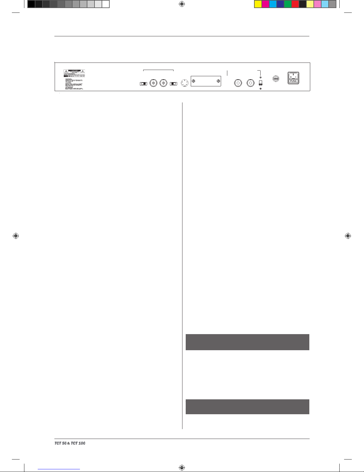
The MAINS POWER switch is self explanatory in that it
turns the mains power supply coming into the amplier off
(0) or on (1).
6
TCT 50.indd 9 2011-5-5 18:32:17

Rear Panel
SERIES EFFECTS LOOP – this consists of the Send
and Return jack sockets, Level switch and Route switch.
The Send socket supplies the preamp output (channel
A and channel B) signal to feed the input of your remote
effects system, whilst the Return socket connects the
output of your effects back into the amplier circuit. Please
remember that the loop is of the “series” type, so that the
entire signal is sent and returned back to the amplifier.
The Level switch has Low and High settings, the setting
of this will be determined by the performance quality of
your effects system, and also how loud the TCT amplier
is set. Low is nominally a loop level of -10dBV, and High is
nominally 0dbV. Experiment with the Level switch to see
what suits your system best.
Effects Loops in general are designed to work with rack
type processors rather than floor stomp boxes. The
reason for this is that most floor pedals do not have
enough headroom to let the signal pass through without
causing the signal to distor t unduly. Also loops are
designed for unity-gain systems (i.e. what goes in, comes
back out at the same amount of gain and signal level) and
are best suited for time based processors like chorusing
and delays, graphic EQ, and studio type compressors.
Denitely do not put gain type pedals (distortion overdrive
etc) in the loop – it really will not sound good, and be very,
very noisy! If you have a good oor type processor, then
by all means experiment for your time delay type effects –
use the low level – it may work, it may not!
The ROUTE switch when set to Bypass disables the Loop
circuit if not being used, which is best practise if not using
the effects loop.
FOOTSWITCH CONNECTOR – the supplied Albion
3-button footswitch connects into this socket for Channel
A-B, MIX switching and Reverb On/Off functions. Please
remember that the front panel channel switches MUST be
pushed in for the remote foot-switching to work.
LOUDSPEAKER OUTPUTS – the two output jack
sockets are parallel wired, so please take this into
consideration when using multi speaker connections. The
accompanying Output Impedance Selector allows the use
of full power connection into either 8 or 16 ohm speaker
systems. I.e. 16 ohm output = 1 x 16 ohm speaker -- 8
ohm output = 1 x 8 ohm speaker OR 2 x 16 ohm speaker.
Warning! The use of any other impedance may cause
damage to your amplier.
The Selector switch is recessed to prevent unknown
accidental switching of the set impedance – to adjust
please use a at screwdriver blade in the selector switch
paddle slot.
The TCT50C 2 x 12” combo is fitted with two 8 ohm
loudspeaker in series for 16 ohm operation. Most Albion
guitar loudspeaker cabinets are also 16 ohm.
HT FUSE – this fuse protects your amplier from further
damage in the case of one of the EL34 output valves
having a failure. WARNING! USE THE CORRECT
REPLACEMENT VALUE ONLY! Using a wrong value can
cause expensive damage to your amplier.
MAINS INPUT – the mains input receptacle allows for
the connection of the mains power cord, and also houses
the mains power fuse. To comply with International Safety
Regulations (for your safety and protection) your amplier
is supplied to work with the mains supply in your country.
Please check the white rating label fitted to the back
panel. If in any doubt, please check with your supplier. It is
of utmost importance to use the correct earthed and rated
power cord, as is supplied with your amplier.
W A R N I N G ! D O N O T U S E W I T H O U T
CONNECTING THE EARTH (GROUND) WIRE.
In the case of the mains fuse blowing, this can be changed
by removing the power cord connector from the amplier
receptacle and with the aid of a small screwdriver the
small drawer in the receptacle can be withdrawn allowing
access to the mains power Fuse.
WARNING! USE THE CORRECT REPLACEMENT
VALUE ONLY!
A WORD OF ADVICE about fuses – if a fuse blows
W A R N I N G ! D O N O T U S E W I T H O U T
CONNECTING THE EARTH (GROUND) WIRE.
W A R N I N G ! U S E T H E C O R R E C T
REPLACEMENT VALUE ONLY!
SERIES EFFECTS LOOP
LEVELRETURN SEND
BYPASSLOOP
ROUTE
LOW HIGH
LOUDSPEAKER OUTPUT SOCKETS
PARALLEL CONNECTED SOCKETS - INTERNAL LOUDSPEAKER = 16ohms
WARNING! DO NOT USE WITHOUT CONNECTING
LOUDSPEAKER LOAD TO AMPLIFIER AND MATCHING
OUTPUT IMPEDANCE TO SPEAKER IMPEDANCE.
16ohm OUT = 1 x 16ohm LS, 8ohm OUT = 1 x 8ohm OR 2 x 16ohm LS
OUTPUT = 35 Watts RMS into 8 or 16 ohms
DO NOT CONNECT ANY UNBALANCED GROUND CONNECTED EQUIPMENT
TO THE OUTPUT OF THIS AMPLIFIER. USE UN-GROUNDED DIFFERENTIAL
MODE ONLY. IF IN DOUBT REFER TO USER MANUAL
35 WATT TWIN CHANNEL VALVE GUITAR AMPLIFIER
FOOTSWITCH
CONNECTOR
8ohm
16ohm
HT FUSE
MAINS INPUT T315mAL 250VT1.6AL 250V
WARNING! USE CORRECT FUSE ONLY
POWER MUTE 100% PHASE +
ACTIVE 33% PHASE -
MAINS
ON POWER OUTPUT
MASTER REVERB
OUTPUT MIX F'BK
POWER AMP RESPONSE
DEEP EDGE
MIX LOWER
1
2
3
46
7
8
9
MIX HIGHER 0
1
2
3
46
7
8
9
10 0
1
2
3
456
7
8
9
10 0
1
2
3
456
7
8
9
10 0
1
2
3
456
7
8
9
10 0
1
2
3
456
7
8
9
10 0
1
2
3
456
7
8
9
10 0
1
2
3
456
7
8
9
10 0
1
2
3
456
7
8
9
10 0
1
2
3
456
7
8
9
10
0
1
2
3
456
7
8
9
10 0
1
2
3
456
7
8
9
10 0
1
2
3
456
7
8
9
10 0
1
2
3
456
7
8
9
10 0
1
2
3
456
7
8
9
10 0
1
2
3
456
7
8
9
10
VOLUME TREBLE MIDDLE BASS DRIVE GAIN
TIGHT
SMOOTH
SHIFT
TIGHT
LOOSE
INPUT
CHANNEL A - PRE EQ
CHANNEL B - POST EQ
A-B MIX
PRESS BOTH
FOR REMOTE
OPERATION
0
1
2
3
456
7
8
9
10
55
A-B/MIX
BALANCE
SERIES EFFECTS LOOP
LEVELRETURNSEND
BYPASS LOOP
ROUTE
LOW HIGH
LOUDSPEAKER OUTPUT SOCKETS
PARALLEL CONNECTED SOCKETS
WARNING! DO NOT USE WITHOUT CONNECTING
LOUDSPEAKER LOAD TO AMPLIFIER AND MATCHING
OUTPUT IMPEDANCE TO SPEAKER IMPEDANCE.
16ohm OUT = 1 x 16ohm LS, 8ohm OUT = 1 x 8ohm OR 2 x 16ohm LS
OUTPUT = 100 Watts RMS into 8 or 16 ohms
DO NOT CONNECT ANY UNBALANCED GROUND CONNECTED EQUIPMENT
TO THE OUTPUT OF THIS AMPLIFIER. USE UN-GROUNDED DIFFERENTIAL
MODE ONLY. IF IN DOUBT REFER TO USER MANUAL
100 WATT TWIN CHANNEL VALVE GUITAR AMPLIFIER
FOOTSWITCH
CONNECTOR
OUTPUT BIAS ADJUST SYSTEM
WARNING! DO NOT REMOVE COVER
8ohm
16ohm
HT FUSE MAINS INPUT
T1AL 250V T2.5AL 250V
WARNING! USE CORRECT FUSE ONLY
CAUTION! NO USER SERVICEABLE PARTS INSIDE.
REFER SERVICING TO QUALIFIED TECHNICIAN
SERIES EFFECTS LOOP
LEVELRETURN SEND
BYPASSLOOP
ROUTE
LOW HIGH
LOUDSPEAKER OUTPUT SOCKETS
PARALLEL CONNECTED SOCKETS
WARNING! DO NOT USE WITHOUT CONNECTING
LOUDSPEAKER LOAD TO AMPLIFIER
OUTPUT = 200 Watts RMS into 8ohms - 300 Watts RMS into 4ohms
DO NOT CONNECT ANY UNBALANCED GROUND CONNECTED EQUIPMENT
TO THE OUTPUT OF THIS AMPLIFIER. USE UN-GROUNDED DIFFERENTIAL
MODE ONLY. IF IN DOUBT REFER TO USER MANUAL
MAINS INPUT T3.15AL 250V
WARNING! USE CORRECT FUSE ONLY
TUNER
FOOTSWITCH
MUTE OUT
LINE OUT
GROUND
CONNECT
ISOLATE
300Watt TUBE PRE/BIPOLAR POWER BASS AMPLFIER
WARNING! DO NOT USE LOAD OF LESS THAN 4ohm IMPEDANCE
OPERATING MANUAL AND USER GUIDE
7
TCT 50.indd 10 2011-5-5 18:32:29

series
Specication
TCT 100 – 100 watt Head amplier
100 watts RMS output into 8 or 16 ohm impedance
loudspeaker load.
5 off 7025/12AX7/ECC83 double triode small signal valves
(tubes)
4 off EL34 power valves (tubes)
HT Fuse = T1A (time lag) 250V rated 20mm glass fuse
Mains Fuse = 100V 50/60 Hz supply = T5AL (time lag)
250V rated 20mm glass fuse
Mains Fuse = 120V 60 Hz supply = T5AL (time lag) 250V
rated 20mm glass fuse
Mains Fuse = 230V 50 Hz supply = T2.5AL (time lag) 250V
rated 20mm glass fuse
Mains Fuse = 240V 50/60 Hz supply = T2.5AL (time lag)
250V rated 20mm glass fuse
Warning! Where fuses specied are rated at 250V please
be aware that this is the rating of fuse value and NOT the
rating of your particular amplier
TCT100H head Dimensions (mm) = 702 (W) x 248 (H) x
259 (D) – Weight = 22Kg
TCT 50 – 50 watt Head amplier, TCT50C – 50 watt 2 x 12”
Combo
50 wat ts RMS output into 8 or 16 ohm impedance
loudspeaker load.
5 off 7025/12AX7/ECC83 double triode small signal valves
(tubes)
2 off EL34 power valves (tubes)
HT Fuse = T500mAL (time lag) 250V rated 20mm glass
fuse
Mains Fuse = 100V 50/60 Hz supply = T3.2AL (time lag)
250V rated 20mm glass fuse
it is usually for a very good reason, it could be anything
from a voltage spike on the mains power, to a serious
malfunction of your amplifier. Fuses are there for your
protection – treat them with respect, and never replace
with the wrong value!
Mains Fuse = 120V 60 Hz supply = T3.2AL (time lag) 250V
rated 20mm glass fuse
Mains Fuse = 230V 50 Hz supply = T1.6AL (time lag) 250V
rated 20mm glass fuse
Mains Fuse = 240V 50/60 Hz supply = T1.6AL (time lag)
250V rated 20mm glass fuse
Warning! Where fuses specied are rated at 250V please
be aware that this is the rating of fuse value and NOT the
rating of your particular amplier
TCT50H head Dimensions (mm) = 702 (W) x 248 (H) x 259
(D) – Weight = 17.9Kg
TCT50C 2x12” combo Dimensions (mm) = 702 (W) x 267 (H)
x 536 (D) – Weight = 33.5Kg
CAUTION! There are no user serviceable parts mounted
inside your amplifier! Refer servicing to suitably qualified
personnel.
AMI 3 WAY FOOT-PEDAL – the 3 way foot-pedal supplied
with your TCT50/100 amplier has a couple of features that
you may want to be made aware of. Firstly the supplied 5
way DIN cable can be replaced if required by any 5 way
DIN lead – either screened or unscreened. Secondly, to
help the foot-pedal t better in with your normal stage set-
up, the cable connection can be made Right Hand (as
supplied) or can be converted to Left Hand connection.
Please see the diagram below.
CAUTION!
There are no user serviceable parts mounted
inside your amplier! Refer servicing to suitably
qualied personnel.
This means that for your own safety and the
correct performance of your amplifier, do not
open the chassis unless you really do know what
you are doing!
8
TCT 50.indd 11 2011-5-5 18:32:30

OPERATING MANUAL AND USER GUIDE
IAG House, Sovereign Court, Ermine Business Park, Huntingdon, Cambs, PE29 6XU, England
www.albionamps.com
The information in this brochure is subject to change without notice.
All rights reserved © 2010 Albion. Albion is a member of the IAG Group.
TCT 50.indd 12 2011-5-5 18:32:32
Other manuals for TCT50
1
This manual suits for next models
1
Table of contents
Other Albion Musical Instrument Amplifier manuals