CARVIN V3 User manual

MODEL V3 AMP SPECIFICATIONS:
RMS Power: 50 or 100 watts
Output Impedance: 4, 8 or 16ohm switch
Input Impedance: 220,000 ohms
Channel Tone Controls: BASS, MID, TREBLE, PRESENCE, EQX
Ch 1 Sensitivity: 1mV for clipping
Ch 2 Sensitivity: 1mV for clipping
Ch 3 Sensitivity: 16mV for full output
Channels: 3—switching
MIDI functions: channel, effect loops and Boost switching,
100 available patch locations, 5-pin jack
Voiced Line Out: 1.5 VAC @ 100 watts RMS
Preamp Tubes: 5—12AX7’s (dual stage)
Power Amp Tubes: 4—EL34 (power pentode)
USA Model: 120VAC, 300VA
6A Circuit breaker
Export Model: 230VAC, 300VA
3A Circuit Breaker
Cabinet Size: 24.25W x 10.5H x 9.5”D
Cabinet: 7-ply poplar wood
Net Weight: 35 lbs
Warranty: One Year
Country of Mfg: Made in USA
Options: -CV3200 cover
-FS44 footswitch - CH1-3, BOOST
-FS22 footswitch - effect loops
-412VT or 412VB
(matching 4x12 speaker cabinets)
CARVIN ENGINEERING DATA OPERATING MANUAL
Congratulations on your purchase of the
V3
all tube amplifier. Carvin has
been building tube guitar amplifiers since 1949. They have been used by top
professionals like Frank Zappa, Steve Vai, Craig Chaquico, Allan Holdsworth,
and other great musicians. You will discover that these amplifiers represent
a significant sound improvement over conventional amplifiers. Spend time
with your new
V3
and get to know its many sounds.
TECHNICAL DESIGN OF THE V3
The V3 design criteria was to build a high peformance 3-channel guitar amplifier with
an all-tube signal path. The V3 has the ability to produce ultra-high gain and bass heavy
sounds with the flexibility to cover all playing styles. The V3 utilizes new ideas built upon
proven tube amplifier technology with an extensive set of features.
FLEXIBLE GAIN STRUCTURES
Each channel of the V3 offers three different gain modes that change the way the
amp reacts to your playing. Different preamp frequencies are enhanced, giving each
setting a different character. Unlike other 3-channel amps, the V3 allows you to set-
up both overdrive channels alike, then change settings to achieve mild or drastic dif-
ferences between the two channels.
MASTER EQUALIZATION
The V3 incorporates three master equalization controls: DEEP, MID CUT, and BRIGHT.
These controls affect the power amp output and allow you to finalize your sound in a
way not available on most amps.
TONE CONTROLS and EQX
The passive BASS, MID, TREBLE tone controls offer a wide range of tone settings.
The greater range of these controls comes from the use of high impedance 1 meg sealed
controls (many guitar amps use only 250k controls). The EQX switch on each chan-
nel takes it one step further, offering a second range of tones to control by shifting
the frequencies affected by the tone controls. The PRESENCE control is designed to
adjust the “edge” on your sound. It’s range allows for super-smooth warm sounds at
lower settings or turn it up to cut through.
TWO “SMART” EFFECT LOOPS
The
V3
features two switching effect loops, one series and one parallel. We called them
“Smart” loops because they recall their settings when you switch between channels 1-3.
For example, you can set the loops off for channel 1, Loop 1 for only Channel 2, and both
loops on for channel 3, or any combination. The TAIL switch activates the long tailed loop
feature, switching off only the “send” and leaving reverbs and delays to decay naturally
the way it’s done in the recording studio.
GIVE YOURSELF A BOOST!
A switchable volume boost is available by footswitch or MIDI. Set the amount of boost
with the BOOST control. When turned on, it will boost your amp’s output by up to
9dB for solos or any time you need to stand out in the mix.
MIDI MEMORY
Set the Channel (1-3), Loops 1&2 (ON/OFF) and Boost (ON/OFF). Put the V3 in “learn”
mode and it will assign your settings to the MIDI patch number you choose from your
controller.
76-33100A 1005
EL34 POWER TUBES
Your amp is equipped with EL34 power tubes because of their powerful output and
responsive tone. The characteristics of these power tubes respond to the wide dynamic
range of guitar playing. These tubes react to the touch. If you play soft the tubes remain
clean and if you increase your attack they respond accordingly.
HIGH IMPEDANCE GUITAR INPUT
Carvin has long known about the effects of miss-loading a guitar pickup, which can
cause high frequency loss. The V3 guards against this loss with its ultra high input imped-
ance. We also considered the capacitance of the average shielded guitar cable which
can reduce the high frequency response of your guitar pickups. Unlike other amplifiers,
we purposely avoided adding capacitance in the preamp to control high frequency oscil-
lations. Instead, we controlled oscillations through careful component layout and lead
placement allowing its shimmering highs to be reproduced.
For your records, you may wish to record the following information.
Serial No._____________________ Invoice Date_______________
RECEIVING INSPECTION—read before getting started
INSPECT YOUR AMP FOR DAMAGE which may have occurred during shipping. If damage
is found, please notify the shipping company and CARVIN immediately.
SAVE THE CARTON & ALL PACKING MATERIALS. In the event you have to re-ship your unit,
always use the original carton and packing material. This will provide the best possible protec-
tion during shipment. CARVIN and the shipping company are not liable for any damage caused
by improper packing.
SAVE YOUR INVOICE. It will be required for warranty service if needed in the future.
SHIPMENT SHORTAGE. If you find items missing, they may have been shipped separately.
Please allow several days for the rest of your order to arrive before inquiring.
RECORD THE SERIAL NUMBER on the enclosed warranty card or below on this manual
for your records. Keep your portion of the card and return the portion with your name and
comments to us.
V3 THREE CHANNEL TUBE GUITAR AMP
12340 World Trade Drive, San Diego, CA 92128
(800) 854-2235 www.carvin.com
c

GETTING STARTED QUICKLY
If you are like most players, you probably want to plug in
your new amp and get started playing it right away. You can
read the rest of the manual later to learn the finer points of oper-
ating your amp. In order to get started you will need your V3
amp, a 120 (or 230) AC grounded power outlet, your instru-
ment, a standard guitar cord, a speaker cord and speaker cab-
inet.
Plug in your speaker and set the “SPEAKER OHMS” switch
to match your speaker. If you have the FS44 footswitch, plug
it into the rear 5-pin “FS44” footswitch jack. If you also have
the FS22 footswitch, plug it into the rear 1/4 inch “FS22”
footswitch jack. Turn all volume controls off. With the amp
turned off, you may now plug it into the proper AC voltage.
Now, plug in your guitar and turn the POWER switch ON. Wait
60 seconds or more for the tubes to warm up, then turn on
the STANDBY switch. The amp will be ready to play in a few
seconds. Gradually raise the channel volume and master volume
controls and re-adjust the tone controls to your liking. Please
call if you feel your amp is malfunctioning. Occasionally tubes
are damaged in shipping.
FRONT PANEL
1. POWER SWITCH
The POWER switch is to be utilized as the master ON/OFF
switch. As the amp is turned on, the large BLUE jewel lamp
LED near the input jack will illuminate as your ON indicator.
2. STANDBY SWITCH
After turning the POWER switch ON, wait 60 seconds or more
for the tubes to warm up - then turn on the STANDBY switch.
When turning the amp OFF, shut off the STANDBY switch first,
then shut off the POWER switch. Use the STANDBY switch if
you are taking a break. This turns the high voltage off,
increasing the life of your power tubes while keeping the power
and preamp tube filaments on for immediate use.
MASTER SECTION
These controls affect all output from the amp.
3. MASTER VOLUME
Controls output of all 3 channels and effects. Once your channel
levels are set up and balanced to each other you may not want to
change them. Use the MASTER to change your overall volume level
for the amp.
4. BOOST CONTROL AND LED
Add up to 9 dB of volume boost via the FS44 footswitch (labeled
EFFECT on the FS44) or MIDI preset. The GREEN LED will light when
the BOOST function is ON. (to switch the BOOST without a footswitch,
see MIDI PROGRAMMING)
5. BRIGHT
Boosts high frequencies starting at 5kHz for added clarity.
Simulate closed or open back cabinets.
6. MID CUT
The MID CUT removes midrange frequencies sometimes referred
to as “muddy”. The MID CUT is a progressive control that varies both
the level and frequency of the cut. At low settings, the MID CUT starts
mildly cutting frequencies in the 900Hz range. At Maximum setting
“10” a deep cut is produced with the frequency centered around
450Hz.
7. DEEP
Turning up the DEEP control adds low frequencies at the sub-har-
monic range. If your speakers sound unfocused or muddy, try reduc-
ing the DEEP control in small steps. This can tighten up your sound
and give your amp a more solid feel. You may want to reset the
MASTER volume after adjusting the DEEP control.
8. SMART LOOPS AND LEDS
The V3 remembers your effects loop settings for each channel. Just
assign a loop(s) to the currrent channel, Smart Loop™ permanently
saves it until you change it. LOOP 1 is a series loop, and LOOP 2
is a parallel loop. The LEDs will also light during MIDI programming.
CHANNEL SELECTION AND INPUT
9. CHANNEL SELECT SWITCHES
Press and release switch
1, 2 or 3 to select the channel to be used. The LEDs next to the chan-
nel’s volume control indicate which channel is functioning. The FS44
footswitch may also be used to select the channel. These switches
are also used to set up MIDI presets (see MIDI IN/THRU).
10. GUITAR INPUT
A standard 1/4” input jack feeds all channels through the SELECT
switches. Use a professional quality guitar cord no longer than 25
feet. Typical cable capacitance should be under 50pf—the longer
the cord, the greater the capacitance (you can measure this with a
capacitance meter). A long cable with high capacitance will reduce
the overall treble response from your pickups.
11. BLUE JEWEL LIGHT
Indicates the POWER is ON.
CHANNELS 1 & 2 OVERDRIVE
The V3 features extensive tone and drive shaping for each channel.
Unlike most 3-channel amplifiers, the V3 allows you to set both over-
drive channels to start with the same sound, then change the con-
trols to get mild or
drastic
differences between the two channels.
12. PRESENCE
Each channel features a PRESENCE control for added clarity. It’s
frequency range is from the mid to high range of the tonal spectrum.
Careful adjustment with the TREBLE control will make this feature
very useful.
13. TREBLE, MID, BASS CONTROLS
To start off with, set the BASS, MID & TREBLE controls at their center
(5) position. These controls are to be set according to the type of
sound you want. Try adjusting the PRESENCE control also when
adjusting the treble.
14. EQX
Toggle between standard EQ and Expanded EQ. This switch opens
a wider frequency range for the TREBLE and BASS,
providing a second set of frequencies to work with.
15. DRIVE MODE 3-POSITION SWITCH
The switch labeled INTENSE/THICK is a 3-position switch that
changes the gain structure of the channel. This provides three choices
of distortion styles:
-"INTENSE"(up)- the most gain and sustain, with excellent picking
articulation. The low-end is deep and percussive. Mids and highs
smoothly blend and still cut through. Turning up the Drive adds more
sustain and saturation.
-”CLASSIC”(center)-rich overdrive with a dynamic response. Turning
up the DRIVE knob adds sustain and harmonics.
-"THICK"(down) - designed with a massive low-end, textured mids
and blistering highs. Turning up the DRIVE knob adds sustain to
the highs and fuller low-end harmonics.
16. DRIVE CONTROL
For mild tube saturation, set the DRIVE control below “4”. For more
harmonics and dynamic playing, set the control between 4 & 6. For
full blown overdrive, set the control between 6 and 10 (your guitar
volume should be turned all the way up).
-Because the V3 has been “Hot Rodded” with so much gain in the
DRIVE control, you may encounter feedback. If feedback is a prob-
lem, reduce the DRIVE or move the guitar to the side or away from
the speaker(s).
17. LED CHANNEL INDICATORS
The blue LED will illuminate when channel 1 is selected.
The red LED will illuminate when channel 2 is selected.
18. CHANNEL VOLUME
Set the volume of the channel to be used. The level of signal coming
out of the EFFECT SENDS will also change. To change the volume
of all channels without upsetting the balance between the 3 chan-
nels, use the MASTER volume control.
CHANNEL 3 CLEAN
19. CLEAN VOLUME
Switch to Channel 3 for”clean” playing. Adjust the DRIVE and VOLUME
controls together to set the level for this channel.
20. LED CHANNEL 3 INDICATOR
The Yellow LED will illuminate when CHANNEL 3 is selected.
21. CLEAN DRIVE
For the cleanest sounds with the most headroom, set the DRIVE
control below “5”. As the DRIVE is turned up, tube dynamics and
harmonics are introduced to your sound. Different sounds can be
achieved by setting the DRIVE MODE switch.
22. DRIVE MODE 3-POSITION SWITCH
The
switch labeled BRIGHT/SOAK is a 3-position switch that changes the
gain structure of the channel. This provides three choices of drive
styles:
-"BRIGHT" - adds high end to the preamp, inviting high frequencies
to chime and sustain as the DRIVE is turned up.
-(CENTER) - A classic, open clean sound with lots of headroom.
Turning up the DRIVE adds harmonics and mild compression.
-"SOAK" - boosts all preamp frequencies. As the DRIVE is turned
up, a vintage snarl is available when played hard.
V3 FRONT & REAR PANEL CONTROLS
1 2 25
23
24
22 21 19
3457
6
30292827
26
8
20

23. CLEAN TREBLE, MID, BASS
You can start at 5 on the dial for each of the tone controls. However,
these settings do not represent a normalized (flat) sound. You need
to set them where they sound best! If your sound is too bright, you
may want to reduce the PRESENCE control.
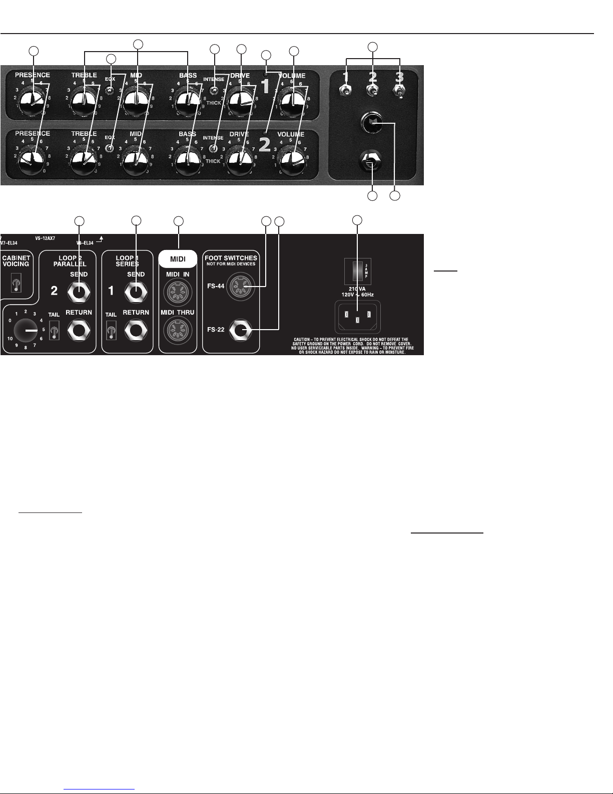
24. CLEAN EQX SWITCH
Toggle between standard EQ and Expanded EQ. This switch opens
a wider frequency range for the TREBLE, MID and BASS. Provides
a second set of tones to work with.
25. CLEAN PRESENCE
For added clarity, the CH 3 PRESENCE controls only the highest guitar
harmonics in the 5-10k Hz range.
Careful adjustment with the
TREBLE control makes this feature even more useful.
REAR PANEL
26. SPEAKER OUTPUT JACKS
Two 1/4” SPEAKER JACKS are featured to operate several speaker
systems at the same time. Calculate the total speaker impedance based
on parallel wiring as the speaker jacks are wired in parallel. Select
the IMPEDANCE SWITCH for the correct impedance.
27. SPEAKER IMPEDANCE SWITCH
The IMPEDANCE SWITCH offers the selection of 4 ohm, 8 ohm or
16 ohm to match your speaker system. The correct setting for two
16 ohm speakers or cabinets would be 8 ohms. The correct setting
for two 8 ohm speakers or cabinets would be 4 ohms. Select the
proper impedance.
28. 4 TUBE 100 WATT OR 2 TUBE 50 WATT OPERATION
For maximum output power, be sure the power tube selector switch
is selected for 4 TUBE operation. For early power amp clipping at
lower levels, move this switch to the 2 TUBE operation. The volume
reduction will only be 3 dB.
29. POWER TUBE BIAS SWITCH
If you desire to change from EL34 to 5881(6L6GC) power tubes,
you may do so by selecting the external BIAS switch to the 5881/6L6GC
position on the rear panel. Be sure that this switch is set to the proper
position or excessive heat will damage your tubes. The internal bias
trim control P27can be set by a qualified technician. To set the bias,
measure the current across the terminals of the STAND BY switch
(set this switch to the off position when the amp is on). Set the idle
current to 100 mA for all tube types.
30. LINE OUT / LEVEL / CABINET VOICING
The LINE OUT 1/4” jack is for connecting to power amps or mixers.
The LEVEL control adjusts the output to prevent overloading amp or
mixer inputs. The CABINET VOICING switch will simulate the fre-
quency response of a guitar cabinet, and prevent excessive bass or
treble going to your mixer. This greatly aids in sound quality because
you do not have to make extreme adjustments to your mixer EQ. The
output level is more than adequate to drive any professional mixer
or power amp.
31. EFFECTS LOOP 2 PARALLEL- SEND/RETURN/TAIL
Effects LOOP2 is configured in
parallel
. This means that the origi-
nal signal is left alone and effects from your processor will be added
into it. This provides the lowest possible noise from an effects proces-
sor without degrading your tone. To use the EFFECTS LOOP2, plug
the INPUT of your effects into the SEND jack and the OUTPUT of your
effects into the RETURN jack. Use shielded cables, not speaker
cables. Set your processor so that no direct signal is heard at the output
(MIX=100%). Adjust the effect level from your processor. If the proces-
sor has no adjustment, or is noisy, adjust the effect level with the LOOP2
RETURN knob. If your processor has a “Direct signal ON/OFF” set-
ting, it is usually better to turn it OFF, so you can set the processor’s
mix or effect level internally by preset. The TAIL switch keeps the
RETURN active after the loop is turned off, allowing reverbs and delays
to decay naturally, instead of being abruptly cut off.
32. EFFECT LOOP1 SERIES - SEND/RETURN/TAIL
Effect Loop 1 is a
series
loop. This means it sends all signals through
your processor. To use LOOP1, plug the INPUT of your effects into
the SEND jack and the OUTPUT of your effects into the RETURN jack.
Use shielded cables, not speaker cables. Adjust the processor MIX
setting to your liking. You may need to re-adjust your processor levels
so that your volume will be the same if LOOP1 is ON or OFF. If your
processor has a “Direct signal ON/OFF” setting, it is usually better to
turn it ON for LOOP1. The TAIL switch keeps the RETURN active after
the loop is turned off, allowing reverbs and delays to decay naturally,
instead of being abruptly cut off.
33. MIDI IN / THRU
Connect any standard MIDI controller to the MIDI IN jack with a 5-
pin MIDI cable. Connect the THRU to other MIDI units if used. (See
“MIDI PROGRAMMING” at the end of this page)
34. FS44 FOOTSWITCH
Use only the Carvin FS44. Buttons labeled “1”, “2”,”3” will choose
your amp channel 1, 2, or 3. The FS44 button labeled “EFFECT” will
turn on/off the BOOST function. DO NOT use MIDI devices in this
jack. Other footswitches will not work.
35. FS22 FOOTSWITCH
The switches on the FS22 footswitch control the EFFECT
LOOPS remotely. They work the same as the SMART
LOOPS switches on the front panel of the V3. Most foot pedals
with 2 switches, a stereo cord and plug will work. However,
Carvin’s FS22 is recommended because no rewiring will be
necessary.
36. AC POWER & CIRCUIT BREAKER
The detachable AC POWER CORD supplied is designed to
operate with one type of voltage (the European 230V export
model uses a CEE-7 plug cord set). Check the rear power
cord label for the proper voltage. Make sure the cord is
securely inserted into the back of the unit. Plug the cord into
a grounded “3” prong” power source. No attempt should
ever be made to defeat or use the amp without the ground
connected.
The circuit breaker is located above the AC power cord recep-
tacle. If the breaker activates, unplug the amp and check
the AC power connection, your speaker connection and all
tubes. If no problem is found and the breaker still activates,
your amp may need service.
MIDI
MIDI PROGRAMMING FEATURES:
The V3 will save the following settings in a MIDI program
patch (1 thru 100):
a.)The channel selection 1, 2, or 3.
b.)The LOOP1 and LOOP2 on/off settings.
c.)The BOOST on/off setting.
Volume, tone, and drive mode settings will not be saved.
TO ENTER MIDI / PROGRAM MODE:
1.) Hold down the channel SELECT switch for the channel
setting you wish to save (1,2,or 3).
2.) While holding down the first switch in step 1, press the
other two SELECT switches, and release
all three
at the same time.
The LOOP1 LED will be flashing.
3.) From your MIDI controller, select (send) the MIDI patch number
you wish to save. The LOOP2 LED will flash once to confirm. Normal
operation is resumed.
To turn the BOOST on before saving the patch, (perform steps 1 and
2 above) then press and release the LOOP 1 switch. The green BOOST
LED will come on. Then perform steps 1-3 to save patch.
TO CHANGE THE MIDI RECEIVE CHANNEL:
1.) Press and release all 3 channel SELECT switches on the front
panel. The LOOP1 LED will be flashing.
2.) Choose MIDI channel 1, 2, or 3 by pressing the SELECT
switch 1, 2, or 3. The LOOP2 LED will flash once to confirm.
Normal operation is resumed.
HELP SECTION
A) FEEDBACK FROM THE LEAD CHANNEL
The V3 may feedback when the VOLUME, DRIVE, TREBLE and PRES-
ENCE are turned all the way up. Like other high-gain tube amps, this
is normal. To help control feedback and noise, reduce the DRIVE con-
trol, or move the guitar to the side or away from the speakers.
Sometimes replacing V1 or V2 (12AX7A) can help reduce feedback.
B) TUBE REPLACEMENT GUIDE
It is not uncommon for tubes to malfunction during shipping. If
your amp is not working properly, please call or refer to the follow-
ing replacement guide.
1) The 12AX7A preamp tubes are the smaller of the two kinds of
tubes, and are located in the following order on your chassis:V1,
V2, V3, V4, V5. To start with, V1 is located by the output trans-
former, which is behind the guitar input. Replace the tubes if your
amp does not work or sounds muddy or dull. V1 is the input
tube and affects all channels. V2 is the main drive tube for chan-
nels 1&2. Replacing V3 will correct problems with channel 3 and
the effect sends. Replace V4 or V5 if no output is heard when
putting a signal through (activated) effect returns.
2) If there is no output after replacing the preamp tubes, or if the
circuit breaker activates, try replacing the EL34 output tubes. The
amp should be rebaised after replacing the output tubes.
3) If the AC breaker should trip and turn the amp off, replace the
power tubes. Most likely one of these tubes might have a short.
10
9
15 16
17 18
11
36
343331
13
14
12
32 35

CAUTION
RISK OF ELECTRIC SHOCK
DO NOT OPEN
SAFETY INSTRUCTIONS (EUROPEAN)
The conductors in the AC power cord are colored in accordance with the following code.
GREEN & YELLOW—Earth BLUE—Neutral BROWN—Live
U.K. MAIN PLUG WARNING: A molded main plug that has been cut off from the cord is unsafe. NEVER
UNDER ANY CIRCUMSTANCES SHOULD YOU INSERT A DAMAGED OR CUT MAIN PLUG INTO A
POWER SOCKET.
IMPORTANT! FOR YOUR PROTECTION, PLEASE READ THE FOLLOWING:
WATER AND MOISTURE: Appliance should not be used near water (near a bathtub, washbowl, kitchen sink, laundry
tub, in a wet basement, or near a swimming pool, etc). Care should be taken so that objects do not fall and liquids are
not spilled into the enclosure through openings.
POWER SOURCES: The appliance should be connected to a power supply only of the type described in the oper-
ating instructions or as marked on the unit.
GROUNDING OR POLARIZATION: Precautions should be taken so that the grounding or polarization means of an
appliance is not defeated.
POWER CORD PROTECTION: Power supply cords should be routed so that they are not likely to be walked on or
pinched by items placed upon or against them, paying particular attention to cords at plugs, convenience recepta-
cles, and the point where they exit from the appliance.
SERVICING: The user should not attempt to service the unit beyond that described in the operating instructions.
All other servicing should be referred to qualified service personnel.
FUSING: If your unit is equipped with a fuse receptacle, replace only with the same type fuse. Refer to replace-
ment text on the unit for correct fuse type.
REFER SERVICING TO QUALIFIED SERVICE PERSONNEL!
THIS UNIT CONTAINS HIGH VOLTAGE INSIDE!
CAUTION
RISK OF ELECTRIC SHOCK
This symbol is intended to
alert the user to the pres-
ence of uninsulated “danger-
ous voltage” within the
product’s enclosure that may be of sufficient
magnitude to constitute a risk of electric
shock to persons.
This symbol is
intended to alert the
user to the presence of
important operating
and maintenance (servicing) instruc-
tions in the literature accompanying
the appliance.
LIMITED WARRANTY
Your Carvin product is guaranteed against failure for ONE YEAR unless otherwise stated. Vacuum
tubes are guaranteed for 90 days. Carvin will service and supply all parts at no charge to the cus-
tomer providing the unit is under warranty. Shipping costs are the responsibility of the customer.
CARVIN DOES NOT PAY FOR PARTS OR SERVICING OTHER THAN OUR OWN. A COPY OF THE ORIG-
INAL INVOICE IS REQUIRED TO VERIFY YOUR WARRANTY. Carvin assumes no responsibility for
horn drivers or speakers damaged by this unit. This warranty does not cover, and no liability is assumed,
for damage due to: natural disasters, accidents, abuse, loss of parts, lack of reasonable care, incor-
rect use, or failure to follow instructions. This warranty is in lieu of all other warranties, expressed
or implied. No representative or person is authorized to represent or assume for Carvin any liability
in connection with the sale or servicing of Carvin products. CARVIN SHALL NOT BE LIABLE FOR INCI-
DENTAL OR CONSEQUENTIAL DAMAGES.
When RETURNING merchandise to the factory, you must call for a return authorization number. If
your unit is out of warranty, you will be charged the current FLAT RATE for parts and labor to bring
your unit up to factory specifications.
HELP SECTION
1) AMP WILL NOT TURN ON
Check the power to the amp. Check for tripped circuit breakers, unplugged extension cords or
power-strip switches that may be turned off. Check the fuse. If a dark brownish color or no wire
can be seen within the glass tube, then replace. The amp may be perfectly fine but occasionally
a fuse may blow because of high AC voltage surges. After the fuse has been replaced with the
proper Slow Blow value and if the fuse fails again, the amp will require servicing.
2) NO OUTPUT with POWER light ON
Tubes damaged in shipping will be the primary reason for your amp to not function properly. Please
give us a call to help guide you through this simple repair.
3) KEEP YOUR AMP LOOKING NEW
Use a damp cloth to wipe the controls on the front & rear chassis panels. Wipe the
black vinyl covering with a damp cloth.
MARK YOUR FAVORITE SETTINGS:
SAMPLE SETTING: SMOOTH LEAD
SAMPLE SETTING: MODERN HEAVY SAMPLE SETTING: BLUES BREAKER
SAMPLE SETTING: SUPER CLEAN
SAMPLE SETTING: CUTTING LEAD SAMPLE SETTING: CLASSIC ROCK RHYTHM
QUICK REFERENCE SETTINGS
Table of contents
Other CARVIN Musical Instrument Amplifier manuals

CARVIN
CARVIN SX50 User manual

CARVIN
CARVIN VT50 User manual

CARVIN
CARVIN MTS3200 User manual

CARVIN
CARVIN SC212C User manual

CARVIN
CARVIN GC212C User manual

CARVIN
CARVIN BX1600 User manual

CARVIN
CARVIN B500 User manual

CARVIN
CARVIN Vintage 16 User manual

CARVIN
CARVIN VL3412B User manual

CARVIN
CARVIN VT50 User manual
Popular Musical Instrument Amplifier manuals by other brands

Duncan
Duncan TARA owner's manual

Korg
Korg TONEWORKS AX3A Easy start

Fender
Fender Super Reverb owner's manual

Hughes & Kettner
Hughes & Kettner tubemeister deluxe 40 user manual

Peavey
Peavey Transtube Series 212 EFX Specification sheet

Mesa/Boogie
Mesa/Boogie Three Channel Dual & Triple Rectifier Solo... owner's manual