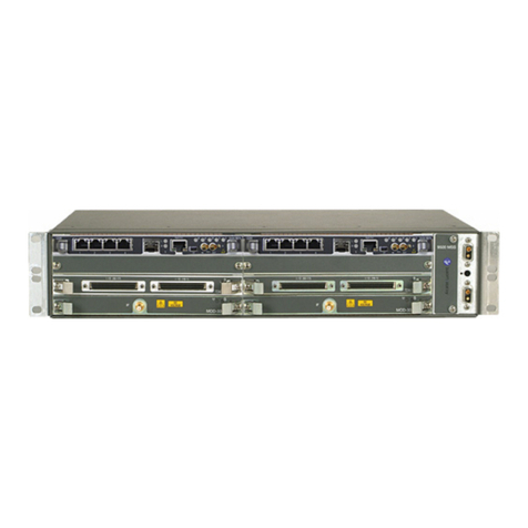
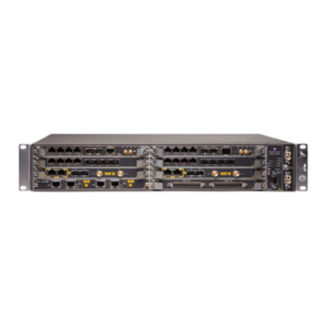
Alcatel-Lucent 9500 MPR-E User manual

9500 MPR-E
Alcatel-Lucent Part Number 3DB18528CAAA
Issue 1, March, 2008
Microwave Packet Radio
Users Manual


TOC-1
Table of Contents
1 General
1.1 Introduction ...............................................................................................................1-1
1.2 Content ......................................................................................................................1-1
2 Operation
2.1 General ......................................................................................................................2-1
2.2 Turn-On .....................................................................................................................2-1
2.3 Craft Terminal (CT) Provisioning Function/Operation ..........................................2-1
2.4 Operating Procedures ...............................................................................................2-1
2.4.1 Rx Radio Protection Switching .................................................................................2-2
2.4.2 Tx Radio Protection Switching .................................................................................2-3
2.4.3 Equipment Protection Switching .............................................................................2-4
2.5 Turn-Off Procedure ...................................................................................................2-5
2.6 Emergency Operation ...............................................................................................2-5
2.7 Module Indicators and Connectors ...........................................................................2-5
3 Interconnect
3.1 INTRODUCTION ......................................................................................................3-1
3.2 POWER CABLE Connection ....................................................................................3-1
3.3 E1 Connections ..........................................................................................................3-3
3.4 Ethernet Cable Connections .....................................................................................3-7
3.4.1 Automatic MDI/MDI-X Configuration .....................................................................3-7
3.4.2 Crossover Cable Option ............................................................................................3-7
3.5 USI/CONTROLLER CABLE CONNECTION to Laptop (J301) ...........................3-10
4 Initial Turnup
4.1 SECTION INTRODUCTION ....................................................................................4-1
4.2 RECOMMENDED Sequence ....................................................................................4-1
4.3 Security Management ...............................................................................................4-2
4.4 Load 9500 MPR Software on PC ..............................................................................4-2
4.5 Turn-On Procedure ...................................................................................................4-2

TOC-2
Page
4.6 Startup ...................................................................................................................... 4-2
4.7 PROVISIONING Radio ............................................................................................ 4-6
4.7.1 Enable Plug-In Cards ............................................................................................... 4-6
4.7.2 Provision Plug-In Cards ........................................................................................... 4-9
4.7.3 Provision Synchronization ..................................................................................... 4-14
4.7.4 Provision NE Time .................................................................................................. 4-17
4.7.5 Crossconnect E1 Lines To Radio Module .............................................................. 4-18
4.7.6 Provision System .................................................................................................... 4-19
4.7.7 Provision Local NE IP Address .............................................................................. 4-20
4.7.8 Provision Ethernet Port 4 ...................................................................................... 4-21
4.7.9 Provision IP Static Routing ....................................................................................4-22
4.7.10 Provision OSPF Static Routing .............................................................................. 4-23
5 Maintenance
5.1 Introduction .............................................................................................................. 5-1
5.2 Maintenance Philosophy .......................................................................................... 5-2
5.3 PERSONAL COMPUTER (PC)/Laptop ................................................................... 5-2
5.4 Troubleshooting ........................................................................................................ 5-2
5.4.1 Before Going to Site Checklist ................................................................................. 5-2
5.4.2 Troubleshooting Basics ............................................................................................. 5-3
5.4.3 Troubleshooting Path Problems ............................................................................... 5-8
5.4.4 Troubleshooting Configuration Problems ............................................................. 5-10
5.4.5 Troubleshooting Ethernet Problems ...................................................................... 5-11
5.4.6 Troubleshooting TMN Problems ............................................................................ 5-12
5.5 Card Removal and REPLACEMENT .................................................................... 5-14
5.5.1 ODU Removal and Replacement ........................................................................... 5-16
5.6 CHANGING FREQUENCY ................................................................................... 5-16
5.7 CLEANING ............................................................................................................. 5-16
6 User Guide
6.1 Introduction .............................................................................................................. 6-1

6.2 Cross-Connect Screen ............................................................................................... 6-1
6.2.1 Helpful Hints ............................................................................................................ 6-1

TOC-3
Page
6.2.2 Cross-Connecting Rules and Guidelines ................................................................. 6-4
6.3 Diagnosis Menu ...................................................................................................... 6-17
6.3.1 Remote Inventory ................................................................................................... 6-17
6.3.2 Abnormal Conditions .............................................................................................. 6-18
6.3.3 Summary Block Diagram View .............................................................................. 6-18
6.4 Supervision Menu ................................................................................................... 6-19
6.4.1 Supervision Dropdown Menu ................................................................................. 6-19
6.4.2 Access State Menu .................................................................................................. 6-19
6.4.3 SW License .............................................................................................................. 6-20
A TCO Suite – Pre-Provisioning
A.1 TCO Main Menu .......................................................................................................A-1
A.1.1 Pre-Provisioning Menu .............................................................................................A-1
A.1.2 Configuration Screen Options ..................................................................................A-4

TOC-4 This page intentionally left blank.

1-1
1
GENERAL
1.1
INTRODUCTION
The information in this Users Manual is a summary of the overall Operation and Mainte-
nance Manual that is located on the attached CD. The summary information is provided to
support initial turnup, day-to-day operation, and maintenance of the 9500 MPR equip-
ment. See Figure 1-1.
1.2
CONTENT
Refer to Table 1-1. The attached CD column lists the parts of the 9500 MPR Radio Family
Operation and Maintenance Manual, PN 3EM22085AAAA. A check mark under the Users
Manual column or the attached CD column indicates where the information is located.
Table 1-1 Information Location
Location
Section/Appendix Users Manual Attached CD
Glossary 3General
Ordering Information
Features and Options
Supplied and Optional equipment
Part Numbers
Physical, Environmental, and Electrical Characteristics
33333Application 3Functional Description 3Physical Installation 3Interconnect
E1
Ethernet 3333Initial Turnup
Radio Provisioning
TMN Specifics 33333Operation
Controls and Indicators 3333Users Guide
Craft Terminal Screen Descriptions 3333Maintenance
Troubleshooting Craft Terminal Alarms
Troubleshooting Using Performance Screens
Troubleshooting TMN Alarms
Module Replacement Procedures
Post-Replacement Test procedures 333333333333Diagrams 3Rack Installation 3Alarm/Status/Control 3Maintenance Support Procedures
Optional Over-The-Hop Performance Tests 33

1-2
Figure 1-1 9500 MPR Family
MSS-8
Microwave Service Switch
ODU V2
Outdoor Unit
MSS-8
8Slots
ODU
V2
9500 MPR
Microwave Packet Radio
9500-1040P
02/20/08

2-1
2
OPERATION
2.1
GENERAL
This section contains turn-on, normal operation, turn-off, and emergency operating proce-
dures plus a description of module indicators and connectors for the 9500 MPR Series
Microwave Packet Radios.
Before performing any procedures, operating personnel should become
familiar with the locations of power distribution units and circuit
breakers. If an equipment performance problem occurs during the fol-
lowing procedures, refer to the Maintenance Section.
2.2 TURN-ON
Radio power is controlled externally via rack and site circuit breakers. The radio is designed to
operate continuously without operator intervention. After initial installation and power turn-on,
operating procedures are limited to periodic visual checks and alarm checks. Turn-on procedures
are needed only if the system has been turned off due to a malfunction or during maintenance.
Until all radios in the transmission link are interconnected, turned
on, and operating properly, alarm conditions may exist.
Perform the following procedure to turn on the 9500 MPR series radios:
1. Set rack power to on.
2.
Verify that no alarm indicator is lighted. If alarm indicator is lighted trou-
bleshoot as described in the Maintenance Section.
2.3
CRAFT TERMINAL (CT) PROVISIONING FUNCTION/OPERATION
The Craft Terminal software is used for maintenance and support of the radio including fault
and status reporting. Refer to the Initial Turn-Up Section for instructions on loading and run-
ning the software. Refer to the User’s Guide Section for descriptions and functions of the menus.
Refer to the Software Release Notes before performing any operating,
provisioning, or maintenance function on this equipment. The Soft-
ware Release Notes may contain information affecting these functions
that is not contained in this instruction manual.
2.4
OPERATING PROCEDURES
The Craft Terminal computer is the main control for the radio. If
instructions for setting up the Craft Terminal computer are needed,
refer to the Initial Turn-Up Section.

2-2
After installation and turn-on, operating procedures are limited to periodic alarm checks.
Automatic and manual switching are provided for equipment protection. Manual switch-
ing may be accomplished using the Craft Terminal screens on the computer. The follow-
ing paragraphs provide operating procedures for manual switchover of protected radio
systems.
2.4.1
Rx Radio Protection Switching
See Figure 2-1 and follow the steps to switch receive traffic between the main and standby
(spare) Radio Access Cards, manually, using the Craft Terminal.
Figure 2-1 Rx Radio Protection Switch
CRI
0
MIN
0
MIN
0
WNG
0
IND
0
MAJ
0
COM
SUP
ALI
OS
NTP
AC
EXT
0
EQP
0
TRS
0
Synchronization Connections
Equipment
Equipment
NE 9500MPR-E 1.0
Slot#0 MSS-8
ODU Dir#7-Ch#1
JUSM_9500MP-E_1.0 - MSS12 - Administrator
Slot#2
Slot#3
Slot#4
Slot#5 MSS/E-1
Slot#1 MSS/CORE-MAIN
Slot#6
Slot#7 MSS/RADIO Dir#7-Ch#
Slot#8
Slot#9 MSS/FANS
9
1
5
3
7
2
6
4
8
Remote Inventory
Alarms Settings
Probable Cause
Severity Event Time
Entity
Alarmed and
201-5/05/07 - 20:00 42
MIN
Target 9500MR3-1
Include alarms from sub-nodes
Help
Protection Schemes
Equipment
Settings Loopbacks
Measurements
Protection 1+1 EPS
Alarms Performance Monitoring
Spare 4 StandBy None Signal
Failure
Main 3 Active None Signal
Failure
Status
Command Criteria
Role Slot
Apply
Help
None
None
Manual
Forced
Command
Commands
Equipment Protection
Tx Radio Protection
Rx Radio Protection
Spare#0 - Slot#4
Main#1 - Slot#3
Spare#0 - Slot#4
Main#1 Slot#3
Spare#0 - Slot#4
Main#1 - Slot#3
JusmMSS Path View Slot #3
Synchronization
Conne
9500-1072
01/31/08
Select None (Default) if there is no command
required or to release a manual or forced switch.
Select Manual if you want to switch from Main to
Standby transmitter or Standby to Main transmitter
and still allow the channel to switch automatically if
there is a failure.
Select Forced if you want to switch from Main to
Standby transmitter or Standby to Main transmitter
and disable automatic switching if there is a failure,
regardless of alarms.
1
4
2
3

2-3
2.4.2
Tx Radio Protection Switching
See Figure 2-2 and follow the steps to switch transmit traffic between the main and
standby (spare) Radio Access Cards, manually, using the Craft Terminal.
Switching the radio transmitter may momentarily interrupt traffic. Before
switching the transmitter, obtain permission from the proper authority.
Figure 2-2 Tx Radio Protection Switch
CRI
0
MIN
0
MIN
0
WNG
0
IND
0
MAJ
0
COM
SUP
ALI
OS
NTP
AC
EXT
0
EQP
0
TRS
0
Synchronization Connections
Equipment
Equipment
NE 9500MPR-E 1.0
Slot#0 MSS-8
ODU Dir#7-Ch#1
JUSM_9500MP-E_1.0 - MSS12 - Administrator
Slot#2
Slot#3
Slot#4
Slot#5 MSS/E-1
Slot#1 MSS/CORE-MAIN
Slot#6
Slot#7 MSS/RADIO Dir#7-Ch#
Slot#8
Slot#9 MSS/FANS
9
1
5
3
7
2
6
4
8
Remote Inventory
Alarms Settings
Probable Cause
Severity Event Time
Entity
Alarmed and
201-5/05/07 - 20:00 42
MIN
Target 9500MR3-1
Include alarms from sub-nodes
Help
Protection Schemes
Equipment
Settings Loopbacks
Measurements
Protection 1+1 EPS
Alarms Performance Monitoring
Spare 4 StandBy None Signal
Failure
Main 3 Active None Signal
Failure
Status
Command Criteria
Role Slot
Apply
Help
None
None
Manual
Forced
Command
Commands
Equipment Protection
Tx Radio Protection
Rx Radio Protection
Spare#0 - Slot#4
Main#1 - Slot#3
Spare#0 - Slot#4
Main#1 Slot#3
Spare#0 - Slot#4
Main#1 - Slot#3
JusmMSS Path View Slot #3
Synchronization
Connections
Select None (Default) if there is no command
required or to release a manual or forced switch.
Select Manual if you want to switch from Main to
Standby transmitter or Standby to Main transmitter
and still allow the channel to switch automatically if
there is a failure.
Select Forced if you want to switch from Main to
Standby transmitter or Standby to Main transmitter
and disable automatic switching if there is a failure,
regardless of alarms.
9500-1073
01/31/08
1
3
4
2

2-4
2.4.3
Equipment Protection Switching
Switching E1 Access Cards may momentarily interrupt traffic. Before
switching E1 Access Cards, obtain permission from the proper authority.
See Figure 2-3 and follow the steps to switch transmit and receive traffic (two directions
with one command) between the main and standby (spare) E1 Access Cards, manually,
using the Craft Terminal.
Figure 2-3 Equipment Protection Switch
CRI
0
MIN
0
MIN
0
WNG
0
IND
0
MAJ
0
COM
SUP
ALI
OS
NTP
AC
EXT
0
EQP
0
TRS
0
Synchronization Connections
Equipment
Equipment
NE 9500MPR-E 1.0
Slot#0 MSS-8
ODU Dir#7-Ch#1
JUSM_9500MP-E_1.0 - MSS12 - Administrator
Slot#2
Slot#3
Slot#4
Slot#5 MSS/E-1
Slot#1 MSS/CORE-MAIN
Slot#6
Slot#7 MSS/RADIO Dir#7-Ch#
Slot#8
Slot#9 MSS/FANS
9
1
5
3
7
2
6
4
8
Remote Inventory
Alarms Settings
Probable Cause
Severity Event Time
Entity
Alarmed and
201-5/05/07 - 20:00 42
MIN
Target 9500MR3-1
Include alarms from sub-nodes
Help
Protection Schemes
Equipment
Settings Loopbacks
Measurements
Protection 1+1 EPS
Alarms Performance Monitoring
Spare 4 StandBy None Signal
Failure
Main 3 Active None Signal
Failure
Status
Command Criteria
Role Slot
Apply
Help
None
None
Manual
Forced
Command
Commands
Equipment Protection
Tx Radio Protection
Rx Radio Protection
Spare#0 - Slot#4
Main#1 - Slot#3
Spare#0 - Slot#4
Main#1 Slot#3
Spare#0 - Slot#4
Main#1 - Slot#3
JusmMSS Path View Slot #3
Synchronization
Connections
9500-1074
01/31/08
Select None (Default) if there is no command
required or to release a manual or forced switch.
Select Manual if you want to switch from Main to
Standby E1 Access or Standby to Main E1 Access
and still allow the channel to switch automatically if
there is a failure.
Select Forced if you want to switch from Main to
Standby E1 Access or Standby to Main E1 Access
and disable automatic switching if there is a failure,
regardless of alarms.
1
4
2
3

2-5
2.5
TURN-OFF PROCEDURE
The radio is designed for continuous operation. If power must be removed while perform-
ing maintenance on a particular cabinet or shelf, power can be removed by turning off
associated site/rack circuit breakers.
Normally, the turn-off procedures are not used. System design allows
maintenance of the rack without interrupting service. It is recom-
mended that turn-off be performed only in an emergency.
2.6
EMERGENCY OPERATION
If an emergency occurs, such as a short circuit or a fire, turn off the 9500 MPR as quickly
as possible.
2.7
MODULE INDICATORS AND CONNECTORS
Do not adjust controls unless instructed to do so in an instal-
lation or maintenance procedure. Unauthorized adjustment
of controls illustrated and described in this section may inter-
rupt traffic and/or degrade system performance.
Module controls, indicators, and connectors used in normal operation or referenced in pro-
cedures are shown in Figure 2-4 through Figure 2-6.

2-6
Figure 2-4 Core Card, Controls, Indicators, and Connectors
S-Card Status
A
-NE
ABNORMAL
ALM (yellow)
W-NE
Warning
ALM (yellow)
m
-NE
minor
ALM (red)
M
-NE MAJOR
ALM (red)
Reset
Pushbutton
9500-1026BE
01/23/08
Sync Out
(Conn-Coax)
Sync In
(Conn-Coax)
Craft
Terminal
SFP Indicators
L-Link
A-Actividy
(Same as RJ45)
Ethernet 1-4
Connectors (RJ45)
SFP
Connector
(USB)
(RJ45)
On-Link Up
Off-Link Down
Blinking-Tx/Rx Activity
Off-No Activity
Link Indicator Activity Indicator
RJ 45 Connector.
Side view showing the small LED lights.
Alarm Status.
See Core Main Module alarm status matrix.
Card Status LED.
Indicates the status of the printed circuit board
as follows:
• Off – Card not equipped, not provisioned,
or not powered
• Green Blinking – Download, software
booting, or flash card realignment in
progress
• Green – In service, normal operation, and
properly provisioned
• Yellow – In standby, properly provisioned
as EPS
• Red – Card fail
• Red Blinking – Card mismatch

2-7
Figure 2-5 E1 Access Card PDH Module Indicators and Connectors
Figure 2-6 Radio Access Card Indicators and Connector
Card Status
9500-1030P
03/23/08
E1
16-1
E1
32-17
Card Status LED.
Indicates the status of the printed circuit board as follows:
• Off – Card not equipped, not provisioned, or not powered
• Green Blinking – Download, software booting, or flash card
realignment in progress
• Green – In service, normal operation, and properly
provisioned
• Yellow – In standby, properly provisioned as EPS
• Red – Card fail
• Red Blinking – Card mismatch
d
Card Status LED.
Indicates the status of the printed circuit board as follows:
• Off – Card not equipped, not provisioned, or not powered
• Green Blinking – Download, software booting, or flash card
realignment in progress
• Green – In service, normal operation, and properly
provisioned
• Yellow – In standby, properly provisioned as EPS
• Red – Card fail
• Red Blinking – Card mismatch
Power Emission Status LED.
Indicates output power status of ODU as follows:
• Off – No Output power (eg: Hot-Standby XMTR, software is
booting, or FPGA downloading is in progress
• Green – Normal output power (+29 dBm Nominal)
• Yellow – Forced squelch enabled on Craft Terminal
• Red – Abnormal output power (high or low limits exceeded)
IF To/From ODU
(QMA) Card Status
Power Emission Status
9500-1028P
03/31/08

2-8 This page intentionally left blank.

3-1
The information contained in this section is a summary of the infor-
mation on the enclosed CD. “Refer to CD” is used throughout this sec-
tion to refer the reader to the detail information on the CD.
3
INTERCONNECT
3.1
SECTION INTRODUCTION
This section gives the location and describes, power connections, signal connections, and
status and alarm connections for the 9500 MPR.
3.2
POWER CABLE CONNECTION
See Figure 3-1 and Figure 3-2 for power cable connection. The power cable (PN 3DB18271AA)
is supplied in the MSS Installation Kit. It is supplied with the connector fitted at one end and
wire at the other. The cable is nominally 5 m (16 ft), and the wires are 4 mm
2
(AWG 12).
The red (or blue) wire must be connected to -48 Vdc (live); the black wire to ground/+ve.
Figure 3-1 Power Cable and Connector
DC power connector can be shorted inadvertently if applied at
an angle. Always insert with correct alignment.

3-2
Short circuiting low-voltage, low-impedance dc circuits can
cause arcing that may result in burns or eye injury. Remove
rings, watches, and other metal jewelry while working with
primary circuits. Exercise caution to avoid shorting input
power terminals.
To protect maintenance personnel from antenna tower light-
ning strikes, the ground system must be integrated by bond-
ing frame ground and dc battery return together.
Figure 3-2 Battery Power Connection

3-3
Do not apply battery power until it is determined that A and
B battery cables with isolated returns and power cables are
wired correctly. With power applied, reverse polarity on wir-
ing (+batt wired to -batt pin on connector) can cause power
supply fuse to blow.
Grounding of pole, antenna, customer interfaces, and all entrances to
the building interior shall meet local electrical code and standard
business practices.
3.3
E1 CONNECTIONS
Recommended connectorized cable assembly – PN 3CC52118AA (22 AWG 34 pair shielded,
jacketed cable with 68-pin SCSI connector on each end). See Figure 3-3 and Figure 3-3 for
connections. Refer to Table 3-1 and Table 3-2 for mating cable wiring.
Figure 3-3 E1 Signal Cable and Connector

3-4
Figure 3-4 E1 Cable Connection (Sheet 1 of 2)
Figure 3-4 E1 Cable Connection (Sheet 2 of 2)
E1/DS1
Cable
Distributor Subrack
(Rear View)
9500-1369
11/06/07
1
E1/DS1 Cable
End 2
E1/DS1 Cable
End 1
32 E1/DS1
PDH Module
Distributor Subrack
(Front View)
9500-1370
11/06/07
1
1
1
Table of contents
Other Alcatel-Lucent Radio manuals

Alcatel-Lucent
Alcatel-Lucent MDR-8000 User manual

Alcatel-Lucent
Alcatel-Lucent MDR-8000 User manual

Alcatel-Lucent
Alcatel-Lucent 9500 MPR User manual

Alcatel-Lucent
Alcatel-Lucent 9558HC User manual

Alcatel-Lucent
Alcatel-Lucent 9500 User manual

Alcatel-Lucent
Alcatel-Lucent 9500 MPR User manual

Alcatel-Lucent
Alcatel-Lucent MDR-8000 User manual

Alcatel-Lucent
Alcatel-Lucent MDR-8000 User manual

Alcatel-Lucent
Alcatel-Lucent 9768 User manual

Alcatel-Lucent
Alcatel-Lucent 9500 MPR User manual